WPI M3301 User manual

Micromanipulators
Care and Maintenance
World Precision Instruments
INSTRUCTION SHEET
Serial No._____________________
052815
www.wpiinc.com

OTHER POPULAR WPI PRODUCTS
The Z-LITE Fiber Optic
Illuminator provides reli-
able, uninterrupted high-
intensity light for micro-
scopes. Z-LITE allows
a continuous range of
subdued or concentrated
lighting controlled by a
rotary dimmer on the
front panel. Z-LITE may
be used with a ring light
and single or bifurcated
flexible fiber bundles, en-
abling the light beam to
be placed exactly where
needed. Forced air cool-
ing prolongs lamp life.
Lamp color temperature
is 3350°K. An interlock
switch automatically
cuts off power when
front panel is opened to
replace bulb.
High intensity
source for
fiber optic
illumination
Bifurcated
Light Guide
500186
available
separately
21" (53 cm)
Z-LITE
Z-Lite Fiber Optic Illuminator (115 V, 60 Hz, beige case)
Z-LITE-Z
Z-Lite Fiber Optic Illuminator (230 V, 50 Hz, black case)
Z-LITE-186
Z-Lite Illuminator & Bifurcated Light Guide
Z-LITE-Z186
Z-Lite Illuminator & Bifurcated Light Guide
LIGHT GUIDES AND ACCESSORIES
500186 Bifurcated Light Guide (with lenses)
R-8-8-WPI01 Ring Light Guide for PZM and PZMIII Series*
13338
Ring Light Adapter (48 mm ∅) for PZM, PZMII, PZMIII
502015 Ring Light Adapter for PZMIV
5475 Adapter for SMA-terminated Fiber Optic Cables
*Ring Light Guide requires adapter #13338 for use with PZM, PZMII and PZMIII,
included with each PZMIII and PZMIV microscope.
503721-12 Iris Forceps, straight, serrated tips, 10 cm (Pack of 12)
503722-12 Iris Forceps, curved, serrated tips, 10 cm (Pack of 12)
503731-12 Webster Needle Holder, 5 in., straight, (Pack of 12)
503706-12
Tuff Cut Scissors, plastic handles, 18 cm (Pack of 12)
503707-12
Tuff Cut Scissors, plastic handles, 14.5 cm (Pack of 12)
503708-12 Iris Scissors, 11.5 cm, straight (Pack of 12)
503709-12 Iris Scissors, 11.5 cm, curved (Pack of 12)
All sales are final on disposable instrument packs.
Economy Surgical Instruments

Micromanipulator Care Guide
World Precision Instruments iii
Copyright © 2013 by World Precision Instruments, Inc. All rights reserved. No part of this publication
may be reproduced or translated into any language, in any form, without prior written permission of
World Precision Instruments, Inc.
CONTENTS
ABOUT THIS MANUAL........................................................................................................................ 1
INTRODUCTION.................................................................................................................................... 1
Notes and Warnings....................................................................................................................... 1
INSTALLING THE TILT BASE............................................................................................................... 2
ADJUSTING THE ANTI-DRIFT TENSION ON MICROMANIPULATORS.................................... 2
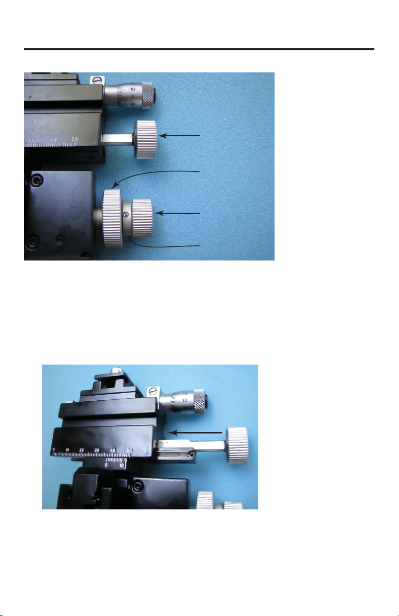
Adjusting the X Coarse Axis Drift ............................................................................................... 3
Adjusting the Y-Axis Drift .............................................................................................................. 6
Adjusting the Z Axis Drift.............................................................................................................. 6
ACCESSORIES........................................................................................................................................ 8
Manipulators.................................................................................................................................... 8
Optional Accessories...................................................................................................................... 8
SPECIFICATIONS................................................................................................................................... 8
KITE .................................................................................................................................................... 8
M3301............................................................................................................................................... 9
MD4R................................................................................................................................................. 9
MMJ.................................................................................................................................................... 9
DC3001............................................................................................................................................. 9
0.2mm/s............................................................................................................................................ 9
WARRANTY..........................................................................................................................................11
Claims and Returns ......................................................................................................................11
Repairs.............................................................................................................................................11

iv World Precision Instruments

Micromanipulator Care Guide
World Precision Instruments 1
ABOUT THIS MANUAL
The following symbols are used in this guide:
This symbol indicates a CAUTION. Cautions warn against actions that can cause
damage to equipment. Please read these carefully.
This symbol indicates a WARNING. Warnings alert you to actions that can cause
personal injury or pose a physical threat. Please read these carefully.
NOTES and TIPS contain helpful information.
INTRODUCTION
Your micromanipulator is a precision instrument. It has been calibrated at the factory and
is ready for use. As with any delicate mechanical device, it needs your care and attention
for long term accurate performance. The following are some helpful hints to make this
possible.
Notes and Warnings
CAUTION: When handling a micromanipulator, set it down gently. Dropping it
(even a short distance) can be damaging to the general alignment and
adjustment.
CAUTION: When not in use, adjust the three (X-Y-Z) guide surfaces in such a way
that they are not exposed and cover the manipulator with a plastic bag. Dirt is
your biggest enemy.
CAUTION: If the manipulator is not in use for a prolonged time, occasionally
work the three surfaces repeatedly back and forth to keep the grease pliable.
Never oil the guide surfaces and under normal use you should not have to apply
grease for many years.
CAUTION: When using the motorized version always be sure to check that the
edge of the micrometer is aligned with the red dots on the motor housing in each
axis before using the manual control for coarse positioning. Running the
motorized axes repeatedly against either end limit can damage the motor. Be advised
that this damage is not covered by any warranty.
CAUTION: When using the dual tool holder micromanipulators, Models MD4R
and MD4L, be careful not to twist the revolving, spring-loaded axes too hard or
too far. This may damage the spring.

2 World Precision Instruments
INSTALLING THE TILT BASE
Fig. 1—(Left) M3 Tilting Base.
Fig. 2—(Right) The M3301 is installed on an M3 Tilting Base with an optional 5 lb. weight
(WPI# 5464).
To install the M3 Tilting Base, remove the ring clamp by removing the two screws with
the Allen wrench provided. Attach the manipulator to the tilting base by using the two
screws provided with the M3. Only two screws are required, because two holes are used
with a right-handed manipulator, and the other two holes in the tilting base are used for
the left-handed version.
ADJUSTING THE ANTI-DRIFT TENSION ON
MICROMANIPULATORS
Fig. 2 shows a side view of the M3301L manual micromanipulator. Depending on the
angle of application and the weight carried on any one guide-way, you may experience
some drift. This can be easily corrected. Follow the procedure on the following pages to
tighten the drag on the coarse manual slides.
In this manual, you can see how to adjust the anti-drift tension on the M3301, but the
procedure is similar for the DC3001R, DC3001L, MD4R, MD4L, KITE-L, KITE-R,
MMJR and MMJL. A micromanipulator axis may begin to move gradually under its
own weight even if it’s not being touched. This phenomenon is referred to as mechanical
drift. It occurs from normal use of the of the manipulator axes over time. Each coarse
axis control (shown below) of the micromanipulator has its own separate adjustment to
counteract drift. What follows is the basic procedure to eliminate drift in each of the axes
through adjustment of the anti-drift tension.

Micromanipulator Care Guide
World Precision Instruments 3
X-Axis Coarse
Adjustment Knob
Z-Axis Coarse
Adjustment Knob
Y-Axis Coarse
Adjustment Knob
Adjustment Ring
Fig. 3—The adjustment controls are labeled on an M3301 micromanipulator.
Adjusting the X Coarse Axis Drift
1. The first step is to rotate the X-Axis Coarse Adjustment knob clockwise until the
x-axis reaches the end of its travel in the fully extended position as indicated by the
black arrow in Fig. 4. This is necessary, because it provides better access to the knob.
In step 2, you will use a pair of pliers to secure this knob while loosening the black
locking nut so that the adjustment can be made.
Fig. 4—Fully extend the X-axis away from adjustment knob.
2. Use a pair of pliers to secure the X-Axis Coarse Adjustment knob to prevent it from
rotating (Figure 3). Don’t grab the knob with the pliers directly, because the jaws will
cut into the aluminum knob. Instead, take a piece of paper and fold it about ½“ wide

4 World Precision Instruments
over upon itself 5 or 6 times to make it thicker. Then, wrap it around the knob to
protect the knob.
0.5” wide paper
folded over
several times
Fig. 5—Wrap the knob with a thick layer of papers so the pliers do not gouge the
aluminum knob.
3. If you are right-handed, hold the pliers in your left hand. With your right hand
insert the special tool (WPI# 502105) (Fig. 6) into the black slot on the end of the
knob. Prevent the silver knob from turning, and rotate the tool counter-clockwise to
unscrew the black locking nut (Fig. 7).
Hold knob and turn
screw counter-
clockwise.
Fig. 6—(Left) 502105 Manipulator Adjustment Tool
Fig. 7—(Right) The outer ring of the knob remains stationary, while you turn the inner
screw counter-clockwise.
4. Once the black locking nut is loose, the silver knob can be freely tightened or
loosened to adjust the amount of resistance to drift. To prevent the axis from moving
while making the tension adjustment, use your left hand to hold the body of the

Micromanipulator Care Guide
World Precision Instruments 5
axis securely while adjusting the silver knob (clockwise to increase tension) with
your right hand. At some point you will feel the resistance of the knob increase
as it begins to compress against the spring steel and nylon friction components.
Adjustment is somewhat arbitrary. When the amount of tension feels about right, use
the 502105 tool to re-tighten the black locking nut to secure the adjustment. Then,
test the anti-drift tension.
5. Test the drift resistance of the axis by pushing on it with your hand to see how easily
it moves. A good technique for doing this is to push on the axis body with your left
thumb while providing a counteracting force on the lower part of manipulator using
your right hand (Fig. 8). When the tension is adjusted correctly, it will not be easy to
move the axis by pushing it.
Apply mechanical
pressure on the X-
axis with left hand
thumb to test for
drift resistance.
Fig. 8—To test the drift resistance, press on the x-axis. It should not move easily.
NOTE: The correct amount of drift resistance depends upon the working orientation of
the manipulator, the load on the axis, and personal preference.
6. If the action feels too tight or too loose, unscrew the black locking nut again and re-
adjust the tension accordingly. It may be necessary to repeat this procedure several
times. Typically, the goal is to get the tension just tight enough to prevent the axis
from drifting under its own weight (while loaded), but not any tighter than necessary
to achieve this end. The correct amount of tension often occurs within a narrow
range of adjustment. If you make it too tight, the knob will be harder than necessary
to turn and the friction components will wear faster. This procedure requires
patience!

6 World Precision Instruments
Adjusting the Y-Axis Drift
The adjustment of the Y-axis tension is performed with essentially the same techniques
as that described for the X coarse axis. The Y-axis is controlled by the Y-Axis Coarse
Adjustment knob shown in Fig. 3.
If the manipulator is operated in standard position (with the electrode clamp located
above the manipulator body as shown in Fig. 2, then the Y-axis does not typically have
a tendency to drift unless the manipulator body is tilted to the left or right relative to the
vertical plane passing parallel through the X-axis.
Adjusting the Z Axis Drift
The Z-axis is notorious for drifting, since it is subject to gravitational forces generated by
the weight of the entire manipulator body and the load.
The adjustment to counteract drift on the Z-axis is performed differently than either the X
or Y axes. The Z-axis is controlled by the Z-Axis Coarse Adjustment knob shown in Fig. 3.
However, the tension is adjusted by rotating the Adjustment Ring.
1. Locate the set screw on the Adjustment Ring (Figure 6).
Set Screw
Fig. 9—The set screw is located on the adjustment ring.
2. Using a small flat blade screwdriver, loosen the set screw by turning the screw
counterclockwise. This will free the Adjustment Ring to allow it to be rotated.
3. Adjust the tension on the Z-axis. The Adjustment Ring may be difficult to turn
manually, because access is limited by the larger diameter Z-axis and Y-axis
Adjustment knobs which surround it. Once the set screw has been loosened, It may
be easier to turn the Adjustment Ring if you keep the screwdriver blade inserted into
the screw and orient the flat blade perpendicular to the direction of the turn. (Fig.
10).

Micromanipulator Care Guide
World Precision Instruments 7
Fig. 10—The flat blade of the screwdriver should be positioned perpendicular to the
adjustment ring to make the ring easier to rotate.
4. The perpendicular position of the screwdriver creates a leverage point for using the
screwdriver to amplify the force applied to turn the ring.
CAUTION: Don’t unscrew the setscrew too much or it will fall out.
CAUTION: Be careful not to let the screwdriver blade slip out of the screw slot,
which could damage the slot or cause personal injury.
TIP: With older manipulators, the Adjustment Ring may be too tight to turn, even using
the screwdriver technique just described. If this is the case, remove the Y-axis
Adjustment knob to gain better mechanical access for the use of pliers.
To remove the Y-axis Coarse Adjustment knob, remove its black locking nut with the
502105 tool. Then, turn the knob counter-clockwise to remove it altogether. Note
the order and orientation of the nylon and spring washer friction components. When
the Z-axis tension adjustments are complete, re-install the friction components and
the Y-axis Coarse Adjustment knob in reverse order of disassembly. Then, re-adjust
the Y-axis tension.

8 World Precision Instruments
ACCESSORIES
Manipulators
KITE-R (or L) Kite Manual Manipulator, right (or left)
KITE-M3-R (or L) Kite, right (or left) + Tilting Base Combo
M3301R (or L) Manual Manipulator, right (or left)
M3301-M3-R (or L) Manual Manipulator, right (or left) with Tilting Base
MD4R (or L) Double Holder Micromanipulator, right (or left)
MD4-M3-R (or L) Double Holder Micromanipulato, right (or left) & Tilting Base
MMJR (or L) Joystick Micromanipulator, right (or left)
SYS-DC3314R Manipulator (right hand) & MS314 Controller
SYS-DC3314L Manipulator (left hand) & MS314 Controller
DC3001R Motorized Manipulator, right hand
DC3001L Motorized Manipulator, left hand
SYS-MS314 Controller for DC3001
Optional Accessories
5464 5-lb Weight for Tilting Base Shipping weight: 7 lb (3 kg)
15873 Optional Angled Electrode Holder (13 cm long)
500475 Ball Joint, 7 cm long, for Ø8mm Holder
500476 Ball Joint, 4 cm long, for Ø4mm Holder
501607 Cable for MS314 and DC3001
502105 Axis Adjustment Tool
M3301EH Replacement Electrode Holder (14 cm long)
M2 Additional Clamp, Ø 12mm
M-3 80° Tilting Base, M6 x 1mm screw
M4C Microscope Stage Adapter
M5 Additional Clamp, Ø 10mm
M6 Additional Clamp Ø 0.5”
PM5 Remote Controller for MS314 and MPM-10
STM3 Joystick Controller for DC300
TBS Tilt Base with Screw Adjustment
A variety of magnetic stands are also available from WPI.
SPECIFICATIONS
KITE TRAVEL RANGE RESOLUTION
X-axis Fine 10mm 0.01mm
X-axis 35mm 0.1mm
Y-axis 20mm 0.1mm
Z-axis 20mm 0.1mm
SHIPPING WEIGHT 3 lbs (1.4 kg)

Micromanipulator Care Guide
World Precision Instruments 9
M3301 TRAVEL RANGE RESOLUTION
X-axis Fine 10mm 0.01mm
X-axis 37mm 0.1mm
Y-axis 20mm 0.1mm
Z-axis 25mm 0.1mm
SHIPPING WEIGHT 3 lbs (1.4 kg)
MD4R TRAVEL RANGE RESOLUTION
X-axis Fine 10mm 10μm
X-axis 37mm 100μm
Y-axis 20mm 100μmm
Z-axis 25mm 100μmm
SHIPPING WEIGHT 3 lbs (1.4 kg)
MMJ TRAVEL RANGE RESOLUTION
X-axis 37mm 0.1mm
Y-axis 20mm 0.1mm
Z-axis 25mm 0.1mm
Joystick (X, Y axes) 0.35~3.5mm
SHIPPING WEIGHT 4 lbs (1.8 kg)
DC3001 TRAVEL RANGE RESOLUTION MAX SPEED
Manual
X-axis 37mm 0.1mm
Y-axis 20mm 0.1mm
Z-axis 20mm 0.1mm
Motorized
X-axis 10mm 0.5μm 0.2mm/s
Y-axis 10mm 0.5μm 0.2mm/s
Z-axis 10mm 0.5μm 0.2mm/s
SHIPPING WEIGHT
DC3001 3 lbs. (1.4 kg)
MS314 1.8 lbs. (0.9 kg)
STM3 2.8 lbs. (1.3 kg)

10 World Precision Instruments

Micromanipulator Care Guide
World Precision Instruments 11
* Electrodes, batteries and other consumable parts are warranted for 30 days only from the date on which the
customer receives these items.
WARRANTY
WPI (World Precision Instruments, Inc.) warrants to the original purchaser that this equipment, including its
components and parts, shall be free from defects in material and workmanship for a period of one year*
from the date of receipt. WPI’s obligation under this warranty shall be limited to repair or replacement, at
WPI’s option, of the equipment or defective components or parts upon receipt thereof f.o.b. WPI, Sarasota,
Florida U.S.A. Return of a repaired instrument shall be f.o.b. Sarasota.
The above warranty is contingent upon normal usage and does not cover products which have been
modified without WPI’s approval or which have been subjected to unusual physical or electrical stress or on
which the original identification marks have been removed or altered. The above warranty will not apply if
adjustment, repair or parts replacement is required because of accident, neglect, misuse, failure of electric
power, air conditioning, humidity control, or causes other than normal and ordinary usage.
To the extent that any of its equipment is furnished by a manufacturer other than WPI, the foregoing
warranty shall be applicable only to the extent of the warranty furnished by such other manufacturer. This
warranty will not apply to appearance terms, such as knobs, handles, dials or the like.
WPI makes no warranty of any kind, express or implied or statutory, including without limitation any
warranties of merchantability and/or fitness for a particular purpose. WPI shall not be liable for any
damages, whether direct, indirect, special or consequential arising from a failure of this product to operate
in the manner desired by the user. WPI shall not be liable for any damage to data or property that may be
caused directly or indirectly by use of this product.
Claims and Returns
Inspect all shipments upon receipt. Missing cartons or obvious damage to cartons should be noted on the
delivery receipt before signing. Concealed loss or damage should be reported at once to the carrier and an
inspection requested. All claims for shortage or damage must be made within ten (10) days after receipt
of shipment. Claims for lost shipments must be made within thirty (30) days of receipt of invoice or other
notification of shipment. Please save damaged or pilfered cartons until claim is settled. In some instances,
photographic documentation may be required. Some items are time-sensitive; WPI assumes no extended
warranty or any liability for use beyond the date specified on the container
Do not return any goods to us without obtaining prior approval and instructions from our Returns
Department. Goods returned (unauthorized) by collect freight may be refused. Goods accepted for
restocking will be exchanged or credited to your WPI account. Goods returned which were ordered by
customers in error are subject to a 25% restocking charge. Equipment which was built as a special order
cannot be returned.
Repairs
Contact our Customer Service Department for assistance in the repair of apparatus. Do not return goods
until instructions have been received. Returned items must be securely packed to prevent further damage
in transit. The Customer is responsible for paying shipping expenses, including adequate insurance on
all items returned for repairs. Identification of the item(s) by model number, name, as well as complete
description of the difficulties experienced should be written on the repair purchase order and on a tag
attached to the item.

World Precision Instruments, Inc.
USA
International Trade Center, 175 Sarasota Center Blvd., Sarasota FL 34240-9258
Tel: 941-371-1003 • Fax: 941-377-5428 • E-mail: sales@wpiinc.com
UK
1 Hunting Gate, Hitchin, Hertfordshire SG4 0TJ
Germany
Zossener Str. 55, 10961 Berlin
China & Hong Kong
WPI Shanghai Trading Co., Ltd.
Rm 20a, No8 Dong Fang Rd., Lu Jia Zui Financial District, Shanghai PRC
Internet
www.wpiinc.com • www.wpi-europe.com • www.wpiinc.cn
This manual suits for next models
8
Table of contents
Other WPI Laboratory Equipment manuals
Popular Laboratory Equipment manuals by other brands

GenBody
GenBody Confiscope g20 user manual

DLab
DLab MS-H380-Pro manual

Hanna Instruments
Hanna Instruments HI 901 instruction manual

PASCO
PASCO SE-9654 instruction manual

Sartorius
Sartorius Sartorius SWC Installation and operating instructions

Bertin Technologies
Bertin Technologies PRECELLYS Evolution Touch user manual