Xilinx Virtex-4 QV FPGA User manual
Other Xilinx Computer Hardware manuals

Xilinx
Xilinx VIODC User manual
Xilinx
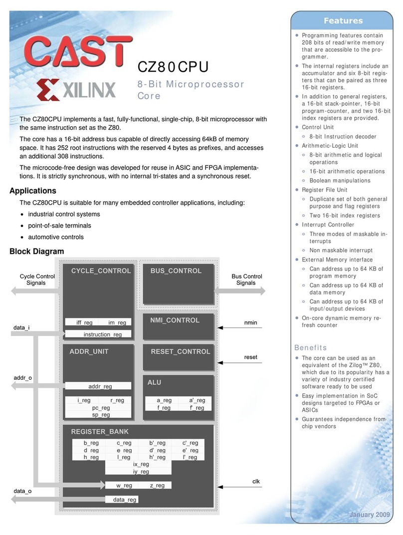
Xilinx CAST CZ80CPU User manual

Xilinx
Xilinx CAN FD v2.0 User manual

Xilinx
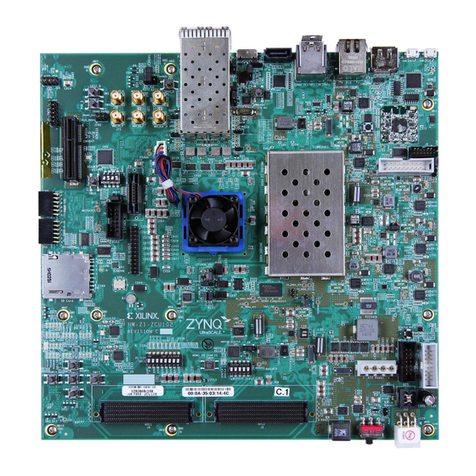
Xilinx ZCU102 User manual
Xilinx
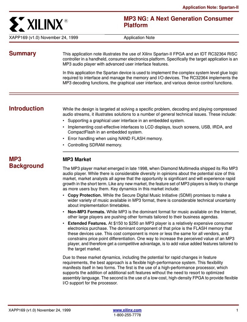
Xilinx XAPP169 Installation and operating instructions

Xilinx
Xilinx ML623 User manual
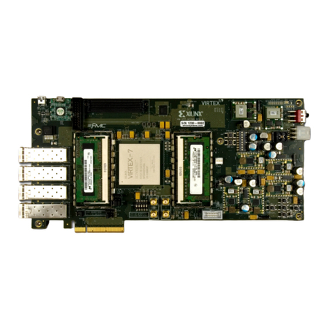
Xilinx
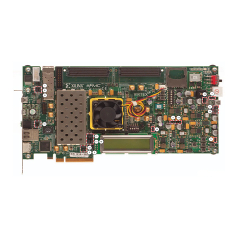
Xilinx VC709 User manual

Xilinx
Xilinx LogiCORE IP Video In to AXI4-Stream v1.0 User manual
Xilinx
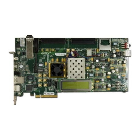
Xilinx KC705 User manual
Xilinx
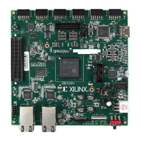
Xilinx SP701 User manual

Xilinx
Xilinx Virtex-5 FPGA ML561 User manual

Xilinx
Xilinx Alveo X3522 User manual
Xilinx
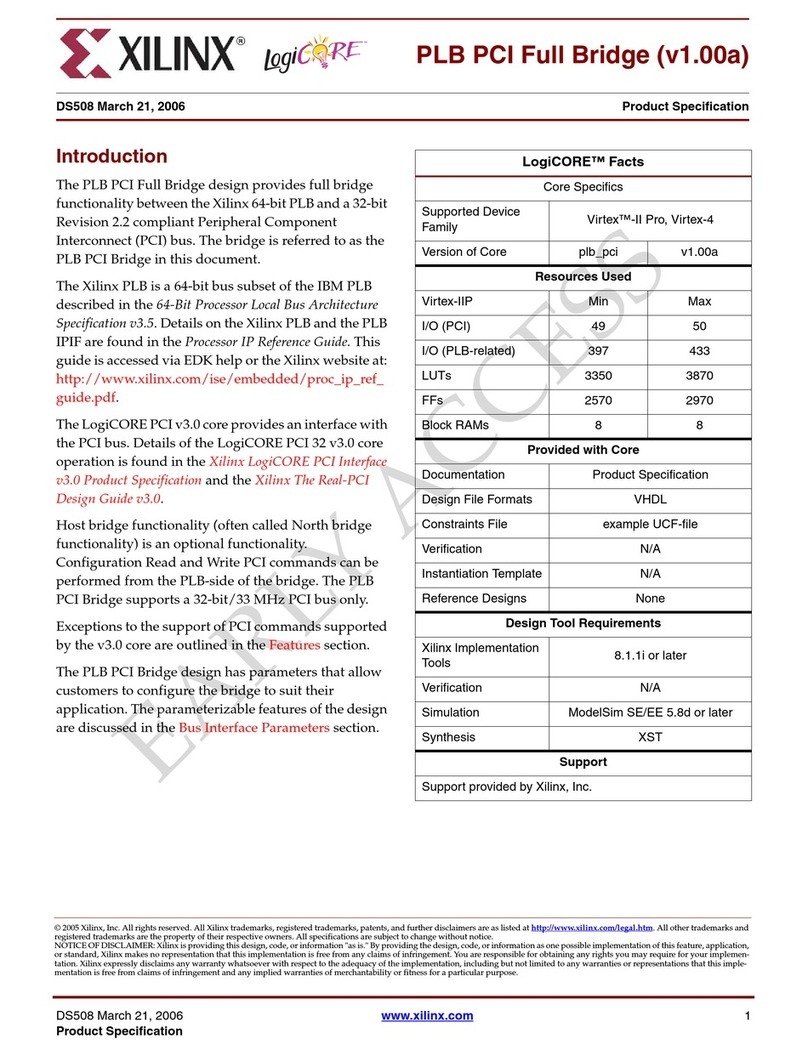
Xilinx LogiCore PLB PCI Full Bridge User manual

Xilinx
Xilinx XM104 User manual

Xilinx
Xilinx Alveo U200 User manual
Xilinx
Xilinx Spartan-3A DSP FPGA Series User manual

Xilinx
Xilinx Alveo X3522 User manual
Xilinx
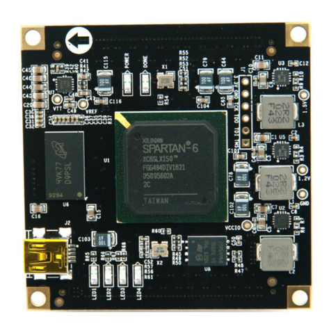
Xilinx ALINX AC6150 User manual

Xilinx
Xilinx DPU IP User manual
Xilinx
Xilinx Virtex-4 FX FPGA User manual
Popular Computer Hardware manuals by other brands

Toshiba
Toshiba TOSVERT VF-MB1/S15 IPE002Z Function manual

Shenzhen
Shenzhen MEITRACK MVT380 user guide

TRENDnet
TRENDnet TEW-601PC - SUPER G MIMO WRLS PC CARD user guide

StarTech.com
StarTech.com CF2IDE18 instruction manual

Texas Instruments
Texas Instruments LMH0318 Programmer's guide

Gateway
Gateway 8510946 user guide

Sierra Wireless
Sierra Wireless Sierra Wireless AirCard 890 quick start guide

Leadtek
Leadtek Killer Xeno Pro Quick installation guide

Star Cooperation
Star Cooperation FlexTiny 3 Series Instructions for use

Hotone
Hotone Ampero user manual

Connect Tech
Connect Tech Xtreme/104-Express user manual

Yealink
Yealink WF50 user guide
