Yale Lockmaster PED1000 User manual

Lockmaster
®
Panic Exit Device
User Guide
An ASSA ABLOY Group brand

Page
02
03
04
05
06-11
12
Index
Operations
Maintenance and service inspection
Panic push bar funtionality test
Maintenance and service inspection
Optional Outside Access Device
Maintenance Log Book
Support
(02)
Index
An ASSA ABLOY Group brand
The safety features of this exit device are of fundamental importance to ensure its compliance with
European Standard EN1125.
No modifications of any kind to the device other than those described in the fitting instructions are permitted.
Attention: Exit devices shall not include dogging (hold unlocked) when fitted to fire or smoke door assemblies.
STRAND
PED1000 Panic Exit Device
Max 2520mm
Max 1320mm
European Patent Application
No. 09155542.5
Max 200kg
0425 - 2326 - 11
Yale Door & Window Solutions
School Street, Willenhall, West Midlands WV13 3PW
www.yaledws.co.uk
EN1125: 2008 3-7-6-0-1-4-2-1-A-A
It is illegal to place windows and external pedestrian doorsets on the market without a CE mark and a Declaration of Performance.
This is due to the European Construction Products Regulation which is EU law. The approved method to demonstrate compliance
with the Construction Products Regulation for external doors and windows is described in the European Standard EN 14351-1
windows and external pedestrian doorsets without resistance to fire and smoke leakage characteristic.
Requirements for emergency or panic exit devices falls under AVCP system 1 and requires that a Notified Body confirms your
compliance by providing a Certificate of Constancy of Performance (CoCoP) for your doorset. Any emergency exit device or panic
exit device fitted to a doorset must have been tested and CE marked (Certificate of Performance available on the Yale DWS
Web Site) to relevant standards EN 179, EN 1125, prEN 13633 or prEN 13637.

(03)
Operations
An ASSA ABLOY Group brand
Operating Mortice Panic Device
To lock device (from inside)
1. Close the door fully and engage the latch
2. Slide the green snib upwards approx 10mm
3. Pull cross arm towards you in an upward arc
to throw hooks and rollers to the locked
position - The hooks and rollers should
engage in strikers
To operate device (from inside)
1. Push cross arm towards door in
a downward arc to release hooks
and rollers allowing door to open
Operating Outside Access Device
To lock device (from outside)
1. Close the door fully and engage the latch
2. Insert key and rotate 145° until some
resistance is felt
3. Turn key a further 35° - this will release
lever
4. Lift the lever up to throw hooks and rollers
to the locked position - the hooks and rollers
should engage smoothly into strikers
5. The key can now be rotated back 180° and
removed from cylinder
To unlock device (from outside)
1. Insert key and rotate 145° until some
resistance is felt
2. Turn key a further 35° - this will release
lever
3. Push the lever downwards to release latch,
hooks and/or rollers allowing door to open
4. The key can now be rotated back 180° and
removed from cylinder
Please note: The Outside Access Device cannot be
left in the unlocked position.
2
3
1
4
3
Hold
Open
Lock
Open
Lock
145°
35°
2 3
1 2

(04)
An ASSA ABLOY Group brand
Maintenance and service inspection
Panic push bar funtionality test
1
2
4
3
Open
Lock
Undo covers and inspect parts and functionality
Oil moving parts
See Maintenance pages
Keep log of inspections
Hold
Test functionality
Door 2
(Double door system only)
Test functionality
Door 1
Open
Lock
Hold

(05)
An ASSA ABLOY Group brand
Maintenance and service inspection - Optional Outside Access Device
1
2
4
3
Test functionality
Test functionality
Open
Open
Lock
5
6
Lock
145°
35°
Undo covers and inspect parts and functionality
Oil moving parts
See Maintenance pages
Keep log of inspections
Test functionality

Exit Door No.
Location
MAINTENANCE INSTRUCTIONS
NOTE: To ensure performance in accordance with BS EN1125 the following routine maintenance checks should be
undertaken at regular intervals.
WEEKLY
1. A visual inspection and operation of the device to ensure that all components are working correctly.
2. Ensure that the strikers are free from obstruction, latches move freely and pass by the striker when operated.
3. Check for any loose components - tighten if necessary.
MONTHLY
1. Check operation of device with door open several times - then again with door closed.
2. Ensure that the strikers are free from obstruction and latches are fully extended when in the closed position.
3. Remove covers and check that all moving parts of mechanisms and latches are lubricated.
4. Check operation of device with covers removed for any obstructions.
5. Check tightness of all fixing screws and replace covers.
6. Check that no additional locking devices have been added to the door since its original installation.
7. Check that all components of the devices are still correct in accordance with the list of approved components
originally supplied with the system.
8. Check that the operating element is correctly tightened and, using a force gauge, measure the operating forces to
release the exit device.
Check that the operating forces have not changed significantly from the operating forces recorded when originally installed.
INSTALLATION AND FIXING INSTRUCTIONS
NOTE: Exit devices manufactured in accordance with BS EN1125 will provide a high degree of safety for people and
reasonable security for property
provided that they are fitted to doors and door frames in good condition. The safety features of the devices are of
fundamental importance to ensure its compliance with the standards. No modifications of any kind other than those
described in the Installation instructions are permitted.
1. Installation instructions specifying appropriate fixing arrangements for the various door types are included with each
exit device.
2. Before fitting an exit device, the door should be checked to ensure correct hanging and freedom from binding. It is
not recommended that exit devices should be fitted to hollow core doors unless specifically designed by the
manufacturer for this type of door. It is recommended to verify that the door construction allows the use of device.
i.e. to verify that offset hinges and engaging leaves allow both leaves to be opened simultaneously, or to verify that the
gap between door leaves does not differ from that defined by the manufacturer, or to verify that the operating elements
do not interfere etc.
3. Before installing an exit device to a fire/smoke door, the certification should be examined to ensure the suitability of
the device for that door assembly. It is of utmost importance that an exit device is not used on a door assembly of a
greater resistance time than approved for.
4. Care should be taken that any seal or weather-strip fitted to the door assembly does not inhibit the correct operations
of the device.
European Patent Application No. 09155542.5
(06)
An ASSA ABLOY Group brand
Maintenance Log Book, page 1

INSTALLATION AND FIXING INSTRUCTIONS
5. On double doorsets with rebated meeting stiles and where both leaves are fitted with exit devices, it is essential to
check that either leaf will open when its respective device is activated and also that both leaves will open freely when
both exit devices are operated simultaneously.
6. Where exit devices are manufactured in more than one size please ensure the correct size is selected.
7. Category 2 (standard projection) exit devices should be used in situations where there is restricted width for escape,
or where the doors are not able to open beyond 90º
8. Where a device is fitted to a glazed door, it is essential that the glazing should be toughened or laminated glass.
9. Alternative fixing screws may be necessary for fitting devices to wood, metal, PVC-U or frameless glass doors.
For more secure fixing, male and female through-door bolts can be used.
10. Exit devices are not intended for use on double action (double swing) doors unless specifically designed by the
manufacturer.
11. The installation instructions must be carefully followed during installation. These instructions and maintenance
booklet should be handed over to the end user, building occupier or the authorised representative after completion.
12. Normally the operating element (push bar or touch bar) should be installed at a height of between 900mm and
1100mm above the finished floor level, when the door is in the secured position. Where it is known that the majority
of the occupants of the premises will be young children, consideration should be given to reduce the height.
13. For panic devices the horizontal bar should be installed so as to provide the maximum effective length (never less than
60% of the door width)
14. The bolt heads, latches and strikers/keepers should be fitted so as to provide secure engagement. Care should be
taken to ensure that no projection of the bolt heads or latches, when in the withdrawn position, could prevent the
door swinging freely.
15. Where panic devices are to be fitted to double doorsets with rebated meeting stiles and self-closing devices, a door
coordinator device according to EN1158 should be fitted to ensure the correct closing sequence of the doors.
Note: This recommendation is particularly important with regard to fire/smoke door assemblies.
16. No additional devices for securing the door in the closed position other than specified herein should be fitted.
This does not preclude the installation of self-closing devices.
17. If a door closing device is to be used to return the door to the closed position, care should be taken not to impair the
use of the doorway by the young, elderly and infirm.
18. Only strikers or keeps plates provided by the manufacturer should be fitted in order to ensure compliance with the
European Standards.
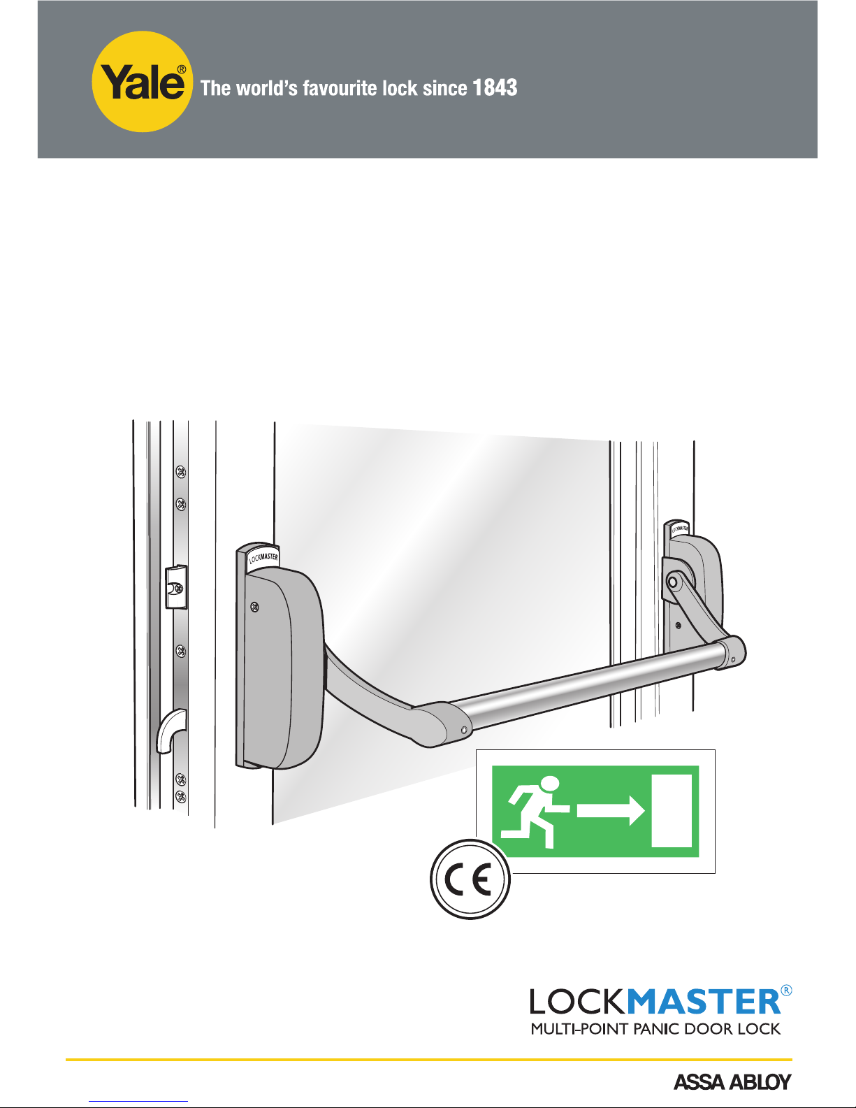
19. For BS EN1125 a sign which reads “push bar to open” or a pictogram should be
provided on the inside face of the door immediately above the horizontal bar.
The surface area of the pictogram should be no less than 8000mm² and its colours
should be white on green background. It should be designed such that the arrow
points to the operating element when installed. (see example of pictogram)
It is hereby declared that this device was installed according to the
manufacturers instructions
................................................................ Signature and Stamp of Installer
Installation and Maintenance Requirements
for Panic Exit Devices
European Patent Application No. 09155542.5
(07)
An ASSA ABLOY Group brand
Maintenance Log Book, page 2

Date Description Signature
(08)
An ASSA ABLOY Group brand
Installation and Maintenance Requirements
for Panic Exit Devices
European Patent Application No. 09155542.5
Maintenance Log Book, page 3

Date Description Signature
European Patent Application No. 09155542.5
(09)
An ASSA ABLOY Group brand
Maintenance Log Book, page 4

(10)
An ASSA ABLOY Group brand
Date Description Signature
European Patent Application No. 09155542.5
Maintenance Log Book, page 5

(11)
An ASSA ABLOY Group brand
Date Description Signature
European Patent Application No. 09155542.5
Maintenance Log Book, page 6

Yale Panic push bar user
Issue 01 06.06.2018
Support available
Installation videos
Available on yaledws.co.uk
and youtube
End user videos
Available on yaledws.co.uk
and youtube
Installation guide
Easy to follow installation
guide/booklet
Maintenance
Ongoing maintenance
guidance and record log
THE YALE BRAND, with its unparalleled global reach and
range of products, reassures more people in more countries
than any other consumer locking solution.
THE ASSA ABLOY GROUP is the world´s leading
manufacturer and supplier of locking solutions, dedicated to
satisfying end-user needs for security, safety and convenience.
PACKAGING FR
(12)
An ASSA ABLOY Group brand
Support
Yale Door and Window Solutions
School Street
Willenhall
West Midlands
WV13 3PW
Table of contents
Other Yale Door Opening System manuals

Yale
Yale 3000 Series User manual

Yale
Yale 2100 Series User manual

Yale
Yale UNOplus 3000 User manual

Yale
Yale YM Series User manual

Yale
Yale 7000 Series User manual

Yale
Yale 3040 User manual

Yale
Yale Tri-Pack 50 Series User manual

Yale
Yale 50 Series User manual

Yale
Yale Tri-Pack 51 User manual

Yale
Yale Delayed Egress 7100 Series User manual

Yale
Yale YM Series User manual

Yale
Yale 3000 Series User manual

Yale
Yale UNI-TJ50BC Series User manual

Yale
Yale 6116 Series User manual

Yale
Yale 150 Series User manual

Yale
Yale 7110 User manual

Yale
Yale UNI Series User manual

Yale
Yale Power Track Series User manual

Yale
Yale YDC201 User manual

Yale
Yale PR50 User manual