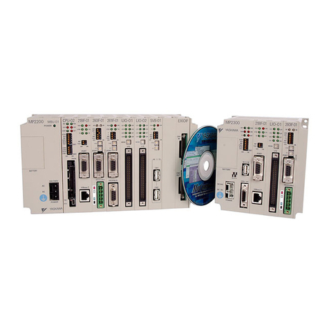
YASKAWA MOTIONPACK-110 Owner's manual
Other YASKAWA Controllers manuals
YASKAWA
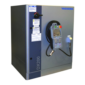
YASKAWA Motoman DX200 User manual
YASKAWA
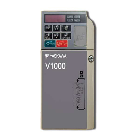
YASKAWA CIMR-VU BA0001 User manual
YASKAWA
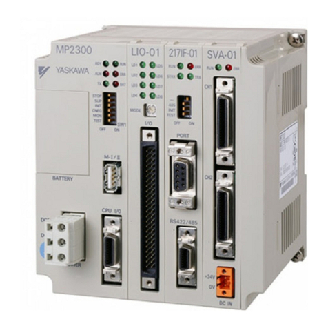
YASKAWA MP2000 Series Programming manual
YASKAWA
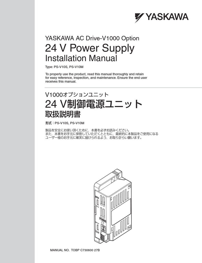
YASKAWA PS-V10S User manual
YASKAWA
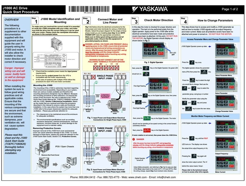
YASKAWA J1000 CIMR-JC series User manual
YASKAWA
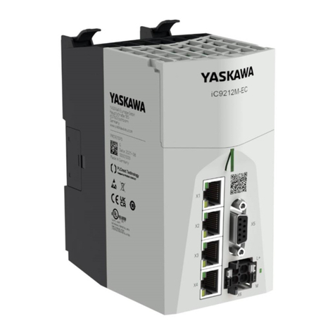
YASKAWA iC9200 Series User manual
YASKAWA
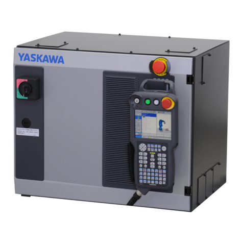
YASKAWA YRC1000 User manual
YASKAWA
YASKAWA YASNAC J50 Quick start guide

YASKAWA
YASKAWA J1000 CIMR-JC series User manual
YASKAWA
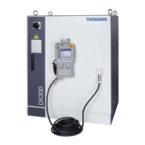
YASKAWA Motoman DX200 User manual
YASKAWA
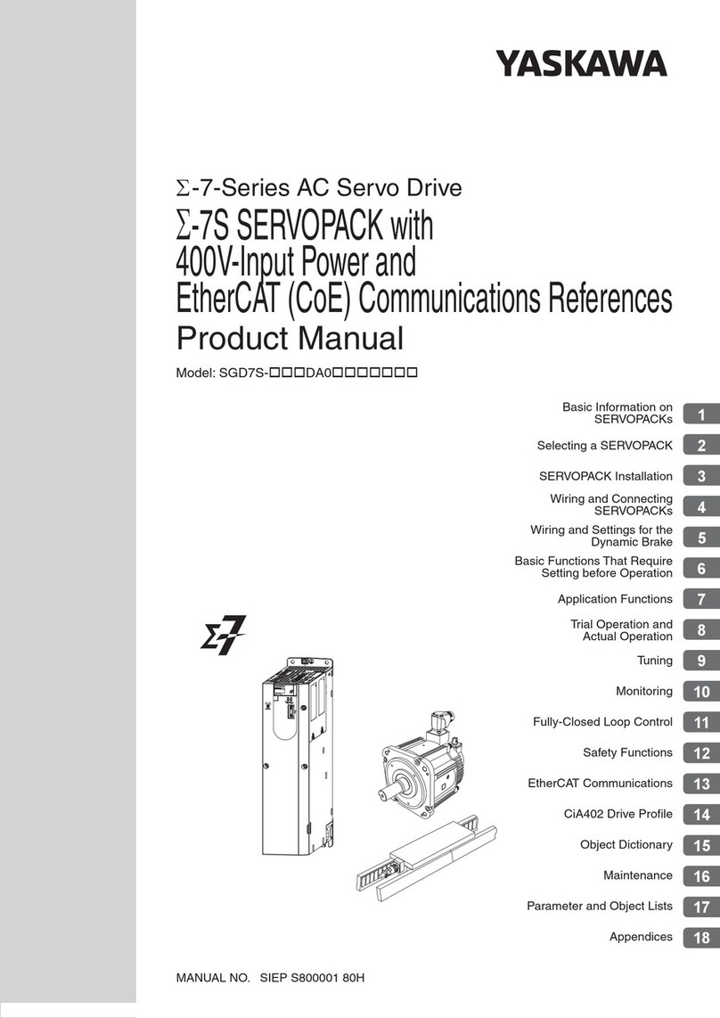
YASKAWA SGD7S-xxxDA0 series User manual
YASKAWA
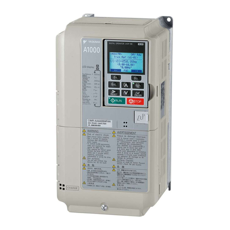
YASKAWA A1000 Series User manual
YASKAWA
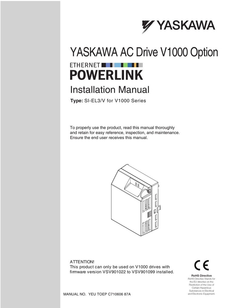
YASKAWA SI-EL3/V User manual
YASKAWA
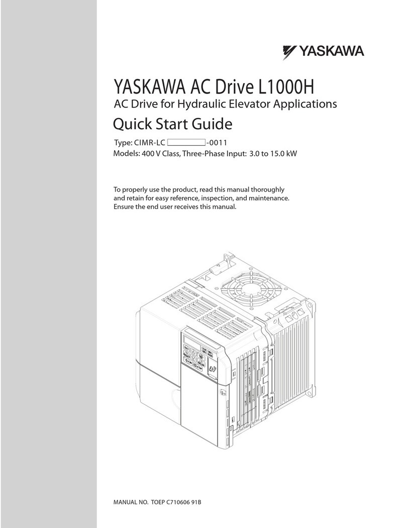
YASKAWA L1000H User manual

YASKAWA
YASKAWA SI-EP3 User manual

YASKAWA
YASKAWA Motoman DX200 User manual
YASKAWA
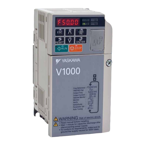
YASKAWA CIMR-V BA0001B User manual
YASKAWA
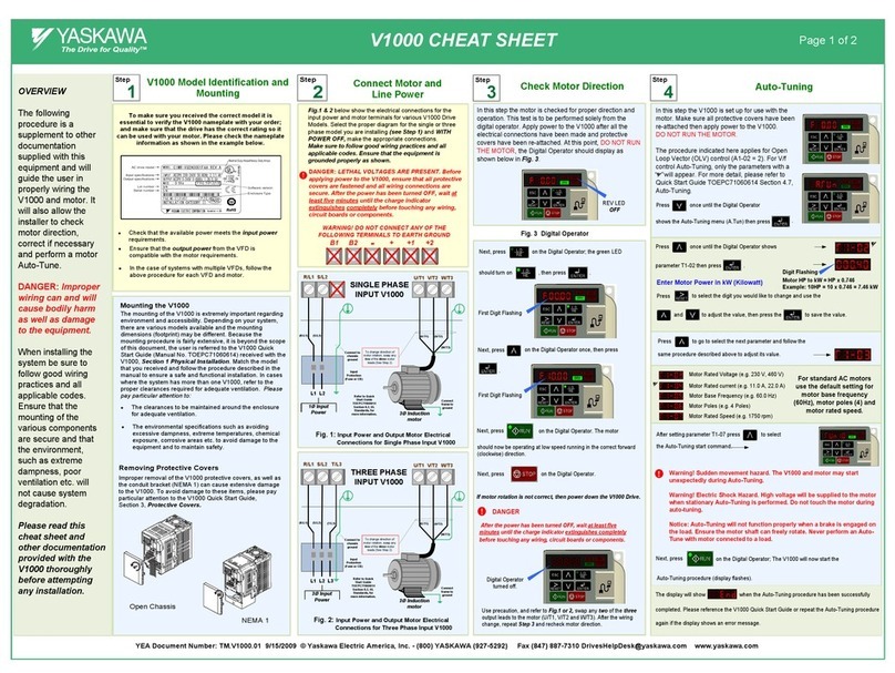
YASKAWA PROFINET V1000 User manual
YASKAWA
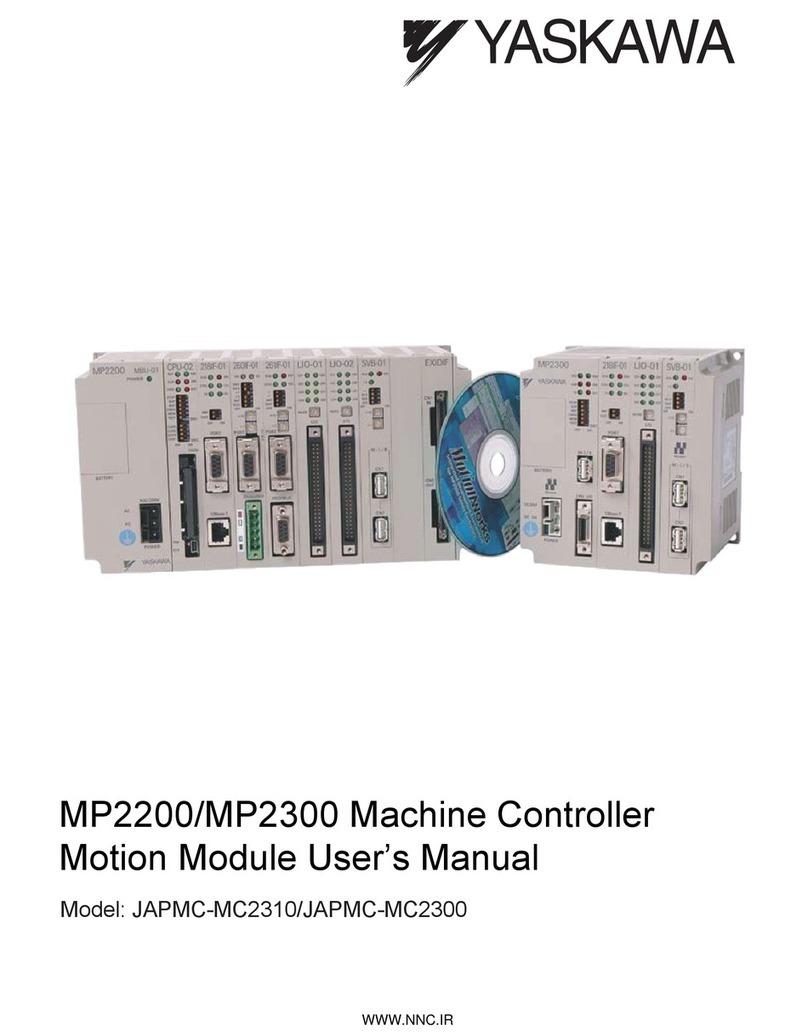
YASKAWA MP2200 User manual
YASKAWA
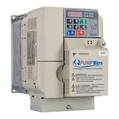
YASKAWA iQpump Micro CIMR-PW Series User manual
Popular Controllers manuals by other brands

Digiplex
Digiplex DGP-848 Programming guide

Sinope
Sinope Calypso RM3500ZB installation guide

Isimet
Isimet DLA Series Style 2 Installation, Operations, Start-up and Maintenance Instructions

LSIS
LSIS sv-ip5a user manual

Airflow
Airflow Uno hab Installation and operating instructions

ABB
ABB ACS580-01 drives Hardware manual
