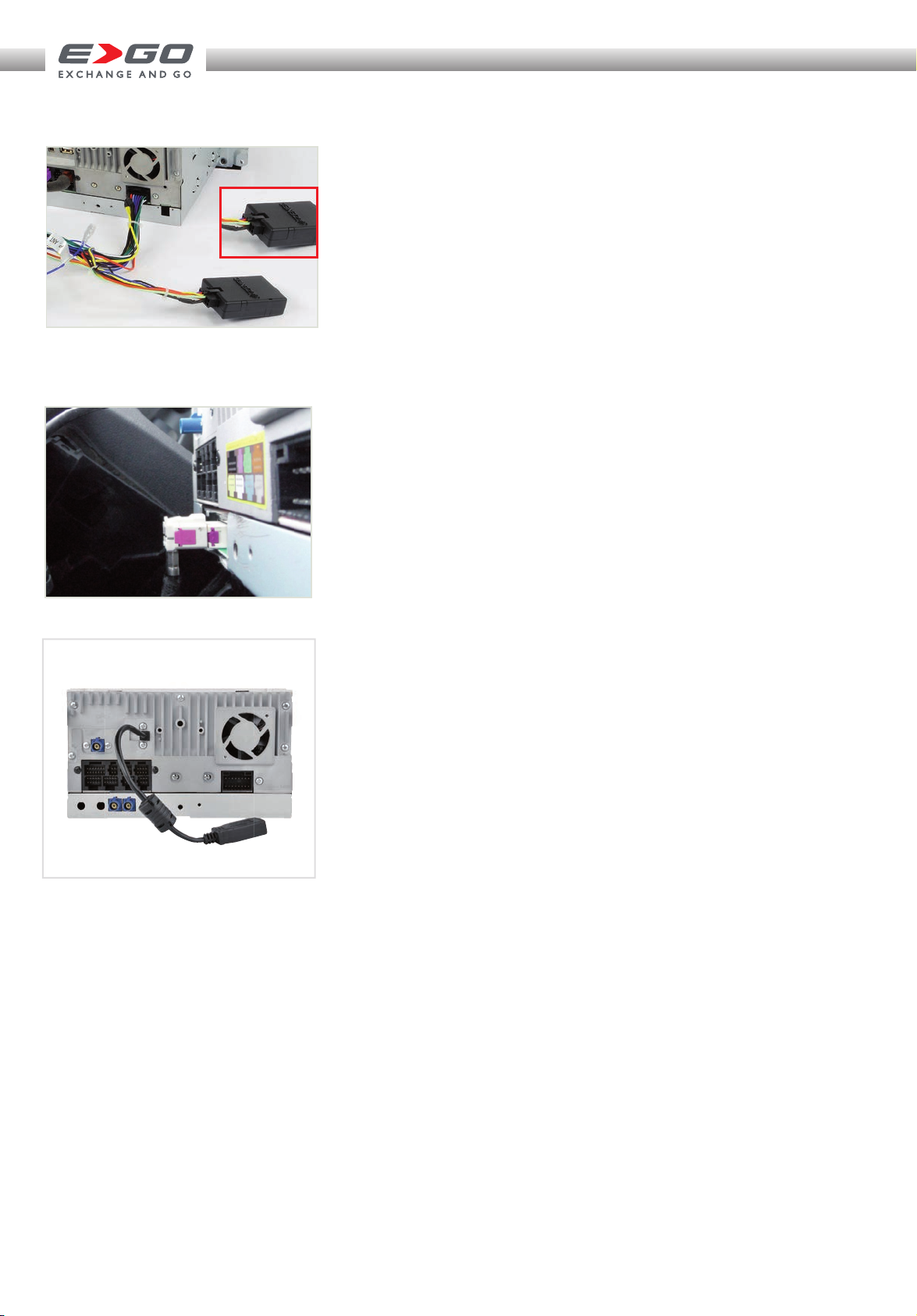
ZENEC E GO ZE-NC3152 User manual

MOUNTING INSTRUCTIONS AUDI TT
ZE-N C 3 15 2

MOUNTING INSTRUCTIONS AUDI TT
Anschlussvorbreitung
Verbinden Sie den entsprechenden
Stecker des Hauptanschlusskabels mit
dem CAN/Stalk Interface).
Das Hauptanschlusskabel wird, wie
im Anschlussdiagramm aufgelistet,
angeschlossen.
Dabei sollten Sie darauf achten, dass
der im Hauptanschlusskabel integrierte
8-polige Stecker entsprechend mit dem
ZE-NC3152 verbunden wird.
Connection preparation
Connect the appropriate connector
of the main connection cable with the
CAN/Stalk interface.
Connect the main connection cable as
described in the electrical connections
overview.
Take care to connect the 8-pin
connector, which is integrated in the
main connection cable, to the
ZE- NC3152.
BITTE BEACHTEN PLEASE NOTE
UKW Antennenkabel mit Doppel-Fakra
Anschluss
Je nach Fahrzeugtype ist der UKW
Antennenstecker als gewinkelte Type
ausgeführt. Das ZE-NC3152 lässt sich in
so einem Fall nicht montieren. Es wird ein
Doppelfakra Verlängerungskabel benötigt
(im Handel gesondert erhältlich).
FM antenna cable with double Fakra
connector
Depending on the vehicle model the
FM double Fakra can be an angled
type, which prevents mounting of the
ZE-NC3152. In such cases, a double
Fakra extension lead is required (to be
purchased separately).

2
1
3
4
5
Entfernen Sie als Erstes die negative
Batterieklemme von der Batterie.
Bevor Sie sich an den Ausbau des
Audi Originalgerätes machen, bereiten
Sie das ZE-NC3152 für den Anschluss
vor. Verbinden Sie das Hauptan-
schlusskabel im Lieferumfang wie im
Anschlussdiagramm zu sehen mit dem
ZE-NC3152. Verbinden Sie nun den
entsprechenden verbleibenden Ste-
cker des Hauptanschlusskabels mit
dem CAN/Stalk Interface.
Remove the negative battery pole
clamp from the battery.
Before you approach the removal
of the OE factory installed device,
start by preparing the ZE-NC3152
for mounting as follows: Connect
the main harness of the set content
to the device as shown in the wiring
diagram. Proceed to connect the
appropriate cable end of the main
harness to the CAN/Stalk interface.
1
M o n t a g e : Installation:
2Lösen Sie mit dem beiliegenden
Entriegelungswerkzeug Ihr
Werksradio aus dem Einbauschacht.
Hierzu müssen alle vier
Entriegelungsschlüssel eingeführt
werden. Das Gerät sollte sich nun
ohne Kraftaufwand herausziehen
lassen.
Unlock the OE factory radio with the
unlock tool contained in the set. You
need to insert all four keys. It should
be possible to pull out the radio
without any brute force applied.
4Ziehen Sie die Kabel aus dem Konso-
lenschacht. Montieren Sie jetzt die
GPS Antenne an geeigneter Stelle
(freie Sicht nach oben) und ziehen Sie
das Antennenkabel in den Schacht.
Montieren sie das externe Bluetooth
Mikrofon, falls erwünscht. Die beste
Position ist hinter dem Rückspiegel,
bzw. hinter dem Steuerrad.
Führen Sie die Airbag Anzeige von
vorne in den ZE-NC3152 ein. Drücken
Sie auf den Einsatz, bis er einrastet.
Pull the cables out of the console, so
they are within reach for device con-
nections to be attempted. Install the
GPS antenna in a suitable location
underneath the front window (unob-
structed view up to the sky). Proceed
with routing the antenna cable to the
mounting slot. Mount the external
Bluetooth microphone, if so desired.
Ideal places are behind the rear mirror
or behind the steering wheel.
Insert the airbag indicator assembly
into the ZE-NC3152. Push on the airbag
indicator until you hear it click in place.
3Um das Gerät vollständig aus dem
Geräteschacht entfernen zu können,
müssen Sie zuvor alle Steckan-
schlüsse (z.B. Hauptanschlusskabel,
Antennenkabel, etc.) auf der Rück-
seite trennen.
Stecken Sie das Kabel von der Airbag
Anzeige unten am Gerät ab. Lösen Sie
den Einsatz mit einem kleinen Schrau-
bezieher und drücken Sie ihn von
hinten aus seiner Halterung.
Legen Sie das Werksradio zur Seite, um
es vor Beschädigungen zu schützen.
To completely remove the factory
radio, all the cables (i.e. main wire
harness, antenna cable etc.) must
be unplugged on the backside of the
device.
Unplug the cable of the airbag indica-
tor on the bottom side of the device.
Unlock and remove the indicator
insert using a small flathead screwdri-
ver, pushing it out from the backside.
Put the radio aside in a safe place, to
protect it from damage.
5Stecken Sie den Quadlockstecker vom
vorbereiteten ZE-NC3152 Gerät an
das Gegenstück im Fahrzeug an und
schliessen Sie die Verriegelung. Ver-
binden Sie die den Fakrastecker vom
GPS Antennenkabel mit dem Gerät
und auch das Kabel vom externen
Mikro, wenn dieses montiert wurde.
Verbinden Sie den Stecker vom Airbag
Einsatz am Stecker Gegenstück vom
Fahrzeug.
Insert the Quadlock plug of the
ZE-NC3152 into the receptor of the
vehicle and lock it. Connect the Fakra
plug of the GPS antenna cable on the
backside of the device – and do the
same with the plug of the external
microphone, if the external mic has
been fitted.
Connect the plug of the airbag
indicator to the connector counterpart
in the mounting slot .

7
6
8
9
bl
Stecken sie den Doppelfakra
Antennenstecker vom Fahrzeug am
Gerät an. Wenn das Fahrzeug über
einen gewinkelten Fakrastecker
verfügt, benötigen Sie ein
Adapterkabel (als Zubehör im
Handel erhältlich). Verstauen Sie
die Kabel in den Randbereichen
und setzen Sie das ZE-NC3152 an
den Schacht an.
Connect the dual Fakra plug of
the two FM antenna leads to
the respective connector on the
backside of the device. If your
vehicle features an angled Fakra
plug, you need to purchase an
adapter cable (sold as accessory).
Now lay all the wires to the side, to
make room for the device. Align the
ZE-NC3152 with the mounting bay.
6
7Wenn alle Anschlusskabel
ordentlich verstaut sind, können
Sie den ZE-NC3152 langsam in den
Einbauschacht einschieben. Gehen
Sie vorsichtig vor, um Schäden an
den hinter dem Gerät befindlichen
Kabeln und Steckern zu vermeiden.
If all the wires have been properly
arranged, you can push back the
ZE-NC3152 in the bay to see, if
there is enough room. Never apply
brute force to avoid shearing of
wires or broken connectors.
9Der Einbau des ZE-NC3152 ist
hiermit beendet.
Befestigen Sie jetzt die negative
Batterieklemme wieder an der
Batterie.
The installation of your ZE-NC3152 is
now complete.
Re-attach the negative pole clamp.
8Wenn genügend Spielraum nach
hinten vorhanden ist, drücken Sie
den ZE-NC3152 soweit nach innen,
bis Sie hören wie die Verriegelung
einklickt.
With some slack left to move and
no obstacle in the way, push back
the ZE-NC3152 until you hear
the clicking sound of the latching
mechanism.
bl Nach beendetem Einbau starten Sie
den Motor und fahren aus der Garage
ins Freie (GPS Antenne braucht „freie
Sicht nach oben“). Schalten Sie das
ZE-NC3152 ein – wechseln Sie nun
manuell in den Navigationsmodus
durch drücken der NAV Taste und
lassen Sie das Gerät ca. 3 - 5 Minuten
lang den „Sat Fix“ erstellen.
Solange das Gerät noch Satelliten
sucht, wird dies über ein Icon mit krei-
senden Punkten auf dem Bildschirm
dargestellt.
Sie können nun das Gerät ausschal-
ten, ein Navigationsziel eingeben oder
aber weitere Einstellungen im Setup
Menü nach persönlichem Wunsch
vornehmen.
With the installation completed, start
the engine and drive your vehicle out
of the garage into open terrain (GPS
antenna must have free “sight up to
the sky”). Turn on the ZE-NC3152 and
select the navigation mode manually
by pressing the NAV button. Device
now needs 3 to 5 minutes to create a
“Sat Fix”.
As long as the device is searching for
GPS satellites, you can see a small icon
with rotating dots on the screen.
You can turn your device off, enter a
destination or continue to set functions
according to personal preferences in
the setup menu.

➜ Das Fahrzeug ist mit einem Eigendiagnosegerät (DME)
ausgestattet.
Um Fehlermeldungen zu vermeiden, muss vor
Montagebeginn unbedingt der negative Pol der
Fahrzeugbatterie abgehängt werden.
➜ Eine einwandfreie Funktion des ZE-NC3152 kann nur
dann gewährleistet werden, wenn Sie das im Lieferumfang
enthaltene Zubehör verwenden.
➜ Es ist nicht nötig, am originalen Anschlusskabel
Veränderungen irgendwelcher Art vorzunehmen.
➜ Achten Sie bei der Installation darauf, dass die
verschiedenen Anschlusskabel und Zubehörteile nicht
durch scharfe Kanten beschädigt und die Anschlusskabel
nicht geknickt werden.
➜ Je nach Präferenz und Wahl des geräteinternen oder
des externen (zu montierenden) Mikrofons, muss im
„Setup Menü“ die Mikrofonquelle für den Bluetooth
Modus entsprechend angepasst werden.
➜ Achten Sie vor der finalen Montage des ZE-NC3152
darauf, dass alle Steckverbindungen auf der Geräte-
rückseite richtig verbunden und fest eingerastet sind.
➜ Bei Fragen oder Problemen wenden Sie sich an
Ihren ZENEC-Händler, bei dem Sie das Gerät gekauft
haben. Zusätzlich finden Sie unter www.zenec.com eine
ausführliche FAQ Datenbank, wo viele der Fragen und
Probleme, welche während der Installation auftreten
könnten, entsprechend beantwortet werden.
➜ Da Updates (Software und Kartenmaterial) für
das Navigationssystem nur über den USB-Anschluss
installiert werden können und sich der USB-
Anschluss an der Rückseite des ZE-NC3152 befindet,
sollten Sie die im Lieferumfang befindliche Media
Link Box unbedingt an einem leicht zugänglichen Ort
installieren. Die Media Link Box verfügt über einen
entsprechenden USB Port.
Bitte Beachten/Please Note
➜ Tampering with the on-board electrical system might
cause error codes to be stored in the DME.
It is thus recommended to disconnect the GND wire of the
negative battery pole before you start with any installation
work.
➜ The flawless function of the ZE-NC3152 can only be
guaranteed, when the original accessories and wire
harnesses contained in the set are deployed as described in
this installation manual.
➜ The ZE-NC3152 is a plug and play product, modifications
on the original wire loom of the vehicle are not required at
all.
➜ When mounting the ZE-NC3152 always pay proper
attention not to damage any of the wires, plugs or other
parts. Avoid applying too much mechanical force especially
when pushing the unit back into the slot.
➜ Depending on the preference and selection of the
device internal or external (to be installed) microphone,
the BT microphone source must be checked and chosen
accordingly, in the setup menu.
➜ Please check if all plug-and-socket connections on the
rear of the ZE-NC3152 are properly seated before you lock
the unit in place.
➜ Please contact your authorized ZENEC dealer or the
distributor of the country, where you have purchased your
E>GO unit, if you have any technical problems or further
questions.
In addition, you can look up a detailed FAQ data base on
www.zenec.com, where most of the questions revolving
around the connectivity or the installation of a given E>GO
model are explained in detail.
➜ Any update of the main unit software or the
navigation system (software and map data) requires
the USB port of the media link box to be present and
accessible. For this purpose, the installation of the
media link box is mandatory. The media link box is
contained in the ZE-NC3152 set – just make sure you
find a good and suitable mounting location that is easy
to access (i.e. glove compartment, arm rest box etc.).

Anschlussdiagramm/Electrical Connections Overview Diagram
ZENEC by ACR AG
Bohrturmweg 1
CH-5330 Bad Zurzach
Schweiz/Switzerland
E-Mail: [email protected]
www.zenec.com
Firma/Company:
Druckfehler und technische Änderungen vorbehalten. Subject to technical changes and misprints.
Stand Dezember 2012 · Rev. A
TOUCH ANOTHER WORLD
ZE-NC3152
CAR SPECIFIC NAVICEIVER (AUDI TT)
Rev. A
Packliste/Packing list
NO. ITEM SKETCH MAP QUANTITY
1
Grundgerät
1
Main unit
2
Externe GPS-Antenne
1
External GPS antenna
3
Hauptanschlusskabel
1
Main wire harness
4
Media Link Box
1
Media link box
5
DVB-T Anschlusskabel
1
DVB-T connection
cable
6
Externes
BT Mikrofon 1
External
BT microphone
7
BT Mikrofon
Adapterkabel 1
BT microphone
interface
8
Steckbares
Anschlusskabel 3
Detachable cable
9
Fernbedienung
2
Remote control
10
Diebstahlschutz-
aufkleber 1
Anti-theft label
11
Bedienungsanleitung
3
User manual
12
Montageanleitung
1
Mounting instructions
13
CAN Bus Interface
1
CAN bus interface
14
USB-Stick
1
USB stick
15
Entriegelungswerkzeug
4
Unlock Tool
Table of contents
Other ZENEC Car Video System manuals

ZENEC
ZENEC ZE-NC524 User manual

ZENEC
ZENEC Z-E2026 User manual

ZENEC
ZENEC ZE-NC2010 User manual

ZENEC
ZENEC ZE-MR902-DVD User manual

ZENEC
ZENEC Z-E3726 Instruction manual

ZENEC
ZENEC ZE-NC3811D User manual

ZENEC
ZENEC ZE-NES14 User manual

ZENEC
ZENEC Z-E2050 User manual

ZENEC
ZENEC ZE-RVC85WA User manual

ZENEC
ZENEC ZE-NC2011D User manual

ZENEC
ZENEC NC3131D User manual

ZENEC
ZENEC ZE-NC4121D User manual

ZENEC
ZENEC ZE-NC510 User manual

ZENEC
ZENEC ZE-NC520 Mounting instructions

ZENEC
ZENEC Z-E3766 User guide

ZENEC
ZENEC ZE-NC510 Mounting instructions

ZENEC
ZENEC ZE-NC2040 User manual

ZENEC
ZENEC ZE-MR1020-DVD User manual

ZENEC
ZENEC ZE-MC5600 - BT COMPATIBILITY LIST V1.9 User manual

ZENEC
ZENEC Z-E2014M User manual