manuals.online logo
Brands
  1. Home
  2. •
  3. Brands
  4. •
  5. ZKTeco
  6. •
  7. IP Access Controllers
  8. •
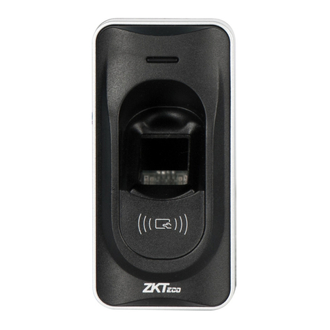
  9. ZKTeco F17 User manual

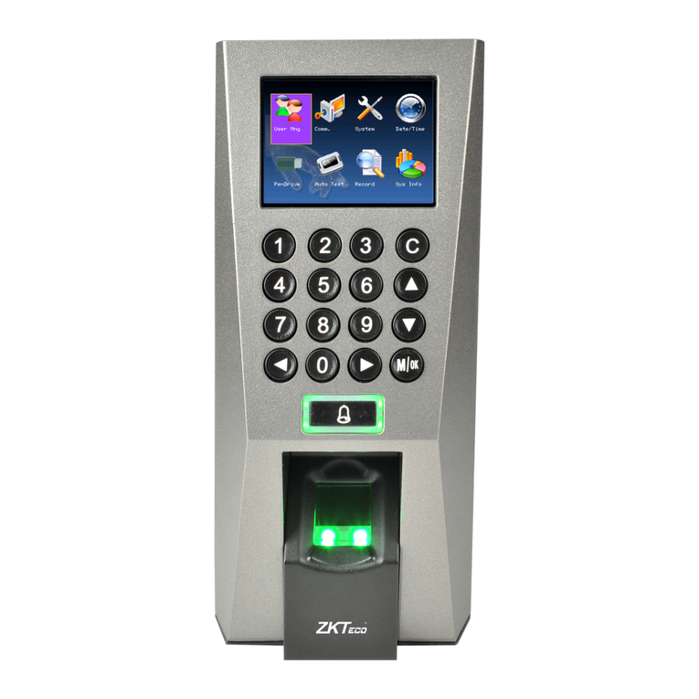
ZKTeco F17 User manual

(1) Post the mounting template on the
wall.Drill the holes according to
the marks on the template (holes
Version: V1.0 Date: April, 2011
(2) Remove the screws on the bottom (3) Take away the back plate.
(5) Tighten the screws on the bottom,
plate on the wall according to the
(4) Fix the plastic pad and the back
RS485 TCP/IP
Lock
Sensor
①
③
Alarm
RS485 Converter
②
NC LOCK
-
+
DC12V
+
NC LOCK
+
-
NO LOCK
-
-
FR 107
+
-
FR 107
+12V +12V
+12V
+12V
GND GND
GND
GND
GND GND
GND
GND
GND
SEN SEN
SEN
SEN
SEN
BUT BUT
BUT
BUT
BUT
BELL+ BELL+
BELL+
BELL+
BELL+
BELL- BELL-
BELL-
BELL-
BELL-
NO LOCK
-
+
DC12V
+
-
+
-
FR 107
-
+
DC12V
+
-
-
+
DC power
-
+
DC12V
-
+
DC power
+
-
FR 107
+
DC12V
-
+
GND
+12V
Exit Button
⑤
External Reader
④
Door Bell
Door Bell
%
%
BUT TON
EXI T
EXI T
BUT TON
⑦
⑥
-
+Alarm
Alarm Power
Exit Button
Door Sensor
for screws and wiring).
of device.
Access Control System Function
(1) If a registered user verified, the device will export the signal
to unlock the door.
(3) If only the d llegal removed, the device will evice being i ly
(4) is External card reader supported.
(5) is it is External exit button supported, convenient to open the
(2) Door sensor will detect the on-off state If the door is unexpected
opened or improperly closed, the alarm signal (digital value) will be
triggered.
export alarm signal.
door inside.
(7) Supports , modes with RS485 TCP/IP to connect PC. One PC can
manage multiple devices.
(6) External door bell is supported.
①: ‘‘I’: device output current, ‘ ’: lock voltage, ’: lock currentULOCK ILOCK
(1) The system supports NO LOCK and NC LOCK. For example the NO LOCK (normally open at power on) is connected
with ’NO’ and terminals, ’COM’ and ’COM’ terminalsand the NC LOCK is connected with ‘NC’ .
(equipped in the package) to prevent the self-inductance EMF affect the system, do not reverse the polarities.
3.Lock Connection
!
Warning: No operating with power on
(1) Share power with the lock:
A. ULOCK=12V, I-ILOCK>1A…… ①
B. The lock is near to the device.
Device share power with the lock:
Device does not share power with the lock:
A. =12V I- ≤1A;ULOCK ILOCK
B ≠12V; . ULOCK
C. The lock is far apart from the device.
Voltage output ≤ DC 12V for Alarm
4. Other Parts Connection:
5. Power Connection:
Input DC 12V, 500mA (50mA standby)
Positive is connected with ‘+12V’, negative is connected
with ’GND’ (do not reverse the polarities).
(2) Does not share power with the lock:
2. Structure and Function
F17 Installation Guide
1. Equipment Installation
(2) When the Electrical Lock is connected to the Access Control System, you need to parallel one FR107 diode
NC1 NC1
NC1
NC1
NC1
NO1 NO1
NO1
NO1
NO1
COM1 COM1
COM1
COM1
COM1
NO2 NO2
NO2
NO2
NO2
COM2 COM2
COM2
COM2
COM2
fix the device to the back plate.
Wir ing Ho le
Inst ruct ion for th e Moun ting Pap er
Befo re the d evice is f aste ned, ple ase
stic k the pa per to the p lace w here you
want t o inst all it, th en mak e holes an d
lay ca bles a ccordi ng to th e mounti ng
pape r.
F17 Mounting Paper
(only for yo ur re fer ence)
Fix ing Hol e
Fix ing Hol e
Fix ing Hol e
10
11
12
13
mounting paper.
DATA0
DATA1
GND
+12V
GLED
RLED
BEEP
Access Control Panel
IWD0
+12V
BEEP
GLED
RLED
IWD1
GND
IP Address:192.168.1.100
Subnet Mask:255.255.255.0
IP Address:192.168.1.124
Subnet Mask:255.255.255.0
Switch
…
Side View Back View
Tamper Magnet
Reset Button
485+ RS485+
485- RS485-
485+
485-
485+ 485-
RS485 Bus
485+ 485- 485+ 485-
RS485
10. Cautions:
6. Wiegand Output
The device supports standard Wiegand 26 output,
so you can connect it with most of the access control
7. Wiegand Input
connect with card reader. Theyan independent are installed each
The device has the function of Wiegand input upports to signal . It s
Wiegand signal extender in long distance or interference environment).
(2) To keep the stability of Wiegand signal, connect the device and the Access Control or Card Reader in same ‘GND’
(1) Please keep the distance between the device and Access Control or Card Reader less than 90 meters(Please use
There are two modes that the PC software communicate and exchange information with the device: RS485 and TCP/IP, and
supports remote control.
9. Communication
8.Other Functions
(1) Manual Reset:
(2) Tamper Function:
(A) Crossover cable: The device and PC connected
(B) Straight cable: The device and PC connected to
(2) TCP/IP Mode:
(1) RS485 Mode:
other restart it.abnormality, you can use ‘Reset’ function to
button hole with than 2mm).a sharp tool (the tip diameter less
Operation: Remove the black rubber cap, then stick the Reset
If the device does not work properly because of misoperation or
In device installation, user need to put a magnet between the device and
the back plate. If the device being illegally , and the magnet beingmoved
away from the device, it will trigger the alarm.
(2)We recommend the 3DC A/12V power supply. Please contact our technical staff for details.
(5)Please connect the ‘GND’ before all the other wiring especially under the environment with much electrostatic.
( )3Please read carefully the terminal description and wiring by rule strictly. Any damage caused by improper
(4)Keep the exposed part of wire less than 5mm, to avoid unexpected connection.
(6)Do not change the cable type because of long distance between the power and the device.
(1)Power cable is connected after all the other wiring. If the device is working abnormally, please shut down the power
first, then make the necessary check . Kindly reminds you that any hot-plugging may damage the device, and
operations will be out of the range of our guarantee.
it is not included in the warranty.
Terminals PC Serial Ports
Converter
!
Warning: No operating with power on
in any case.
side of the door, to control the lock and access together.
Please use specified RS485 wire, RS485 active converter and
bus-type wiring.
Terminals definition please refer to the right table.
LAN/WAN through switch/Lanswitch.
Two ways for TCP/IP connection.
directly.
devices by now.
485+
485-
TXD
RXD
GND
GND
WD0
WD1
DATA0
GND
DATA1
(7) Please use specified RS485 wire, RS485 active converter and bus-type wiring. If the communication wire is longer than 100
meters, it is needed to parallel a terminal resistance on the last device of RS485 bus, and the value is about 120 ohm.

Other manuals for F17

1

Other ZKTeco IP Access Controllers manuals

ZKTeco G4 User manual

ZKTeco

ZKTeco G4 User manual

ZKTeco Green Label ProFace X User manual

ZKTeco

ZKTeco Green Label ProFace X User manual

ZKTeco FaceKiosk-H10A User manual

ZKTeco

ZKTeco FaceKiosk-H10A User manual

ZKTeco ZKX5030A User manual

ZKTeco

ZKTeco ZKX5030A User manual

ZKTeco SpeedFace-VSL Series User manual

ZKTeco

ZKTeco SpeedFace-VSL Series User manual

ZKTeco F18I User manual

ZKTeco

ZKTeco F18I User manual

ZKTeco ZPad Plus User manual

ZKTeco

ZKTeco ZPad Plus User manual

ZKTeco BR1200 Series User manual

ZKTeco

ZKTeco BR1200 Series User manual

ZKTeco Green Label ProlD104 User manual

ZKTeco

ZKTeco Green Label ProlD104 User manual

ZKTeco MB20-VL User manual

ZKTeco

ZKTeco MB20-VL User manual

ZKTeco ProMA Series User manual

ZKTeco

ZKTeco ProMA Series User manual

ZKTeco UR10RWF User manual

ZKTeco

ZKTeco UR10RWF User manual

ZKTeco ProFace X SL User manual

ZKTeco

ZKTeco ProFace X SL User manual

ZKTeco TF1600 ZKTeco User manual

ZKTeco

ZKTeco TF1600 ZKTeco User manual

ZKTeco F6 User manual

ZKTeco

ZKTeco F6 User manual

ZKTeco MultiBio 700 User manual

ZKTeco

ZKTeco MultiBio 700 User manual

ZKTeco BioPro SA30 User manual

ZKTeco

ZKTeco BioPro SA30 User manual

ZKTeco ZKX Series User manual

ZKTeco

ZKTeco ZKX Series User manual

ZKTeco OP-200 User manual

ZKTeco

ZKTeco OP-200 User manual

ZKTeco Notus User manual

ZKTeco

ZKTeco Notus User manual

ZKTeco FR1200 Datasheet

ZKTeco

ZKTeco FR1200 Datasheet

ZKTeco ProCapture-WP User manual

ZKTeco

ZKTeco ProCapture-WP User manual

ZKTeco F17 User manual

ZKTeco

ZKTeco F17 User manual

ZKTeco BioServer 2 User manual

ZKTeco

ZKTeco BioServer 2 User manual

Popular IP Access Controllers manuals by other brands

Navkom ARX-manager user manual

Navkom

Navkom ARX-manager user manual

FingerTec k-Kadex user guide

FingerTec

FingerTec k-Kadex user guide

SecuGen Hamster Air user guide

SecuGen

SecuGen Hamster Air user guide

EverFocus EBC890 user guide

EverFocus

EverFocus EBC890 user guide

V-TEK DT607C-S1 user manual

V-TEK

V-TEK DT607C-S1 user manual

Immotec iSafe Pro 360 Verso technical information

Immotec

Immotec iSafe Pro 360 Verso technical information

eKey Home Information sheet

eKey

eKey Home Information sheet

Nayar Systems GSR Lite manual

Nayar Systems

Nayar Systems GSR Lite manual

Gantner GAT Access 6100 F user manual

Gantner

Gantner GAT Access 6100 F user manual

Roger QUADRUS SERIES operating manual

Roger

Roger QUADRUS SERIES operating manual

D-Link DWS-4026 user manual

D-Link

D-Link DWS-4026 user manual

Lock Control ST-780 Series Operation and installation manual

Lock Control

Lock Control ST-780 Series Operation and installation manual

Miaxis Biometrics SM-621 user manual

Miaxis Biometrics

Miaxis Biometrics SM-621 user manual

Security Brands ASCENT M8 install guide

Security Brands

Security Brands ASCENT M8 install guide

EURA AC-30C7 User Manual and Guarantee Card

EURA

EURA AC-30C7 User Manual and Guarantee Card

H3C WX6103 installation guide

H3C

H3C WX6103 installation guide

Honeywell MPA2 installation guide

Honeywell

Honeywell MPA2 installation guide

Fermax AC-MAX INSTALLATION WIRING GUIDE

Fermax

Fermax AC-MAX INSTALLATION WIRING GUIDE

manuals.online logo
manuals.online logoBrands
  • About & Mission
  • Contact us
  • Privacy Policy
  • Terms and Conditions

Copyright 2025 Manuals.Online. All Rights Reserved.