ABB GE SPST480 User manual

•
Voltage
Number Rating (1)
Peak Inrush
Current, mA(2) Nominal RMS
Current, mA
SPST480
480 Vac 375 21
SPST600 600 Vac 300
17
SPSTL480
480 Vac 750 20
SPSTL600 600 Vac 600 16
(1)
Rated for 50/60 Hz. Rating is 120 Vac without
step-down transformer.
Peak inrush current is present for 2-6 ms after activation. This
number is provided so that fuses and supplies can be chosen
appropriately.
(2)
—
Table 1. Catalog numbers and voltages for the Shunt Trip and Shunt Trip with Lockout
Voltage Peak Inrush
Accessory Rating Current, A
Nominal RMS
Current, mA
Shunt Trip 120 Vac 1.5 85
Shunt Trip/
120 Vac 3 80
Lockout
—
Figure 1. Shunt Trip with Lockout
1
AVERTISSEMENT:
Les modules de déclenchement shunt
480 Vac et 600 Vac doivent être utilisés avec le
transformateur abaisseur de tension qui est fourni.
AVERTISSEMENT:
Avant d'installer tout accessoire, mettre
le disjoncteur en position OFF, le d éconnecter de
toute tension d'alimentation, et décharger les
ressorts d'armement.
WARNING:
Before installing any accessories, turn the
breaker OFF, disconnect it from all voltage sources, and
discharge the charging springs.
The Shunt Trip or Shunt Trip with Lockout will cause the
circuit breaker to trip when the control voltage is greater
than 55% of the rated ac value. Control power to the Shunt
Trip must be removed before the breaker can be closed.
Control power to the Shunt Trip with Lockout must be
removed for a minimum of 0.25 second before the breaker
can be closed.
Catalog
—
Table 2 Voltage and current ratings for the 120 Vac Shunt Trip and Shunt Trip with
Lockout.
Installation
The Shunt Trip and Shunt Trip with Lockout accessories,
shown in Figure1, can be installed in 800-4000 ampere frame
Power Break® II circuit breakers. These accessories allow the
breaker to be tripped electrically from a remote location.
In addition to providing a trip signal to the breaker, the Shunt
Trip accessories can be set up to interact with other Power
Break II accessories, when used with a MicroVersaTrip Plus or
MicroVersaTripPM Trip Unit. DIP switches on the rear of the
breaker Trip Unit can configure the Shunt Trip accessories to
activate a Bell Alarm-Alarm Only accessory or a Bell Alarm
with Lock out accessory when a shunt trip occurs. The
Accessory Configuration section below describes how this can
be done. If the breaker is equipped with a Power+Trip Unit, it
is configured so that only protection trips will activate a Bell
Alarm Alarm Only or Bell Alarm with Lockout.
The catalog numbers for the Shunt Trip and Shunt Trip with
Lockout for 480 and 600Vac are listed in Table 1. Voltage and
current ratings in Table1 are given at the input of the
transformer. The voltage and current ratings of the input to
the accessory are equal to that of the 120Vac version of the
accessory. Table 2 Iists these ratings.
GEH6519 INSTRUCTIONS
Power Break® II Circuit Breaker Accessories
Shunt Trip and Shunt Trip with Lockout 480& 600Vac
Introduction
Operation
Apply control voltage to the primary of the supplied step-
down transformer. The secondary of the transformer is
connected to terminals 31 and 32 of the terminal strip on the
right side of the breaker.
WARNING:
480 Vac and 600 Vac Shunt Trip accessories
must be used with the supplied step-down transformer

The Shunt Trip or Shunt Trip with Lockout is installed in the
accessory compartment through the front of the circuit
breaker in the position shown in Figure 2.
Shunt Trip or
Shunt Trip with Lockout
Bell Alarm Bell Alarm-
with Alarm Only
Lockout
Undervoltage Release
shunt trip occurs, with the procedure described in
the Accessory Configuration section.
Mount the supplied step-down transformer near the
circuit breaker.
Connect the control wiring for either Shunt Trip to
the primary side of the transformer, marked as the H
numbered terminals. Table 3 lists the correct
transformer primary taps.
Connect the secondary side of the transformer,
marked as the X numbered terminals, to terminals 31
and 32 of the terminal block on the right side of the
breaker. Table 3 lists the correct transformer
secondary taps.
Primary
Secondary
Catalog Number/
Control Voltage Connections Connections
9T58K0042
H1, H4(1) X1, X2
480 V
9T58K0062 H1, H4 X1, X3
600 V
Test the Shunt Trip to ensure proper operation,
according to the procedures below.
Reconnect power to the circuit breaker and any other
accessories.
Close and lock or seal the door over the accessory
compartment and Trip Unit to prevent unauthorized
changes to Trip Unit settings and to keep
contaminants out of empty accessory slots.
�
Accessory Configuration
This section only applies if Alarm-Alarm Bell Only or Bell
Alarm with Lockout accessories are installed in the breaker,
along with a MicroVersaTrip Plus or MicroVersaTrip PM Trip
Unit. If the breaker is equipped with a Power+ Trip Unit, the
factory default settings, listed in Table 4, can not be
changed.
The Shunt Trip accessory can be configured to activate the
Bell Alarm-Alarm Only or Bell Alarm with Lockout accessories
if a shunt trip occurs. The configuration can be changed by
removing the Trip Unit from the breaker, setting the DIP
switches on the rear of the Trip Unit, and reinstalling the Trip
Unit. Figure 4 illustrates the Trip Unit rear DIP switches and
their functions. Table 4 lists the switch functions and the
factory settings for each.
Use the following procedure to install the Shunt Trip accessory
into the Shunt Trip slot of the accessory compartment:
Tighten the locking screw on the front of the accessory
until it is snug(9 in-lb).
(1) A jumper must be placed from H2 to H3.
Open the hinged door over the accessory compartment
and Trip Unit.
To remove an existing accessory, loosen the accessory
locking screw and pull the accessory out with the Rating
Plug Removal Tool (catalog number TRTOOL).
Insert the Shunt Trip accessory into the proper slot, as
illustrated in Figure 3. The Shunt Trip accessory is keyed
for the correct slot in the accessory compartment. If the
accessory cannot be fully seated in the compartment,
check that the compartment position is correct.
WARNING:
480Vac and 600 Vac Shunt Trip accessories must
be used with the supplied step-down transformer.
AVERTISSEMENT:
Les modules de d éclenchement shunt
480 Vac et 600 Vac doivent être utilisés avec le
transformateur abaisseur de tension qui est fourni.
—
Figure 2 Accessory compartment on front of circuit breaker, with Shunt Trip slot indicated.
1.
2.
3.
—
Figure 3. Inserting a Shunt Trip into the accessory compartment.
4.
CAUTION:
Over tightening the locking screw may damage
or distort the case of the accessory.
ATTENTION:
Le serrage excessif de la vis de verrouillage
peut déformer le boîtier d'accessoire.
—
Table 3. Primary and secondary connections for step-down transformers.
9.
10.
11.
If the breaker is equipped with a MicroVersaTrip Plus or
MicroVersaTrip PM Trip Unit, the Shunt Trip accessory
can be configured to activate installed Bell Alarm-Alarm
Only or Bell Alarm with Lockout accessories when a
5.
8.
9.
7.
6.
2

Description of Switch Settings
Following are descriptions of the effects of each accessory
switch when it is
enabled.
When a Shunt Trip accessory causes the breaker to trip,
the contacts of the Bell Alarm-Alarm Only also change
state. (The factory switch setting is
disabled.
)
F
actory
Switch
Setting
1 Di sabled
2 Di
sabled
3 E nabled
4 Di
sabled
5 Di sabled
6 E
nabled
AVERTISSEMENT:
Avant de commencer cette
procédure, mettre le disjoncteur en position OFF, le
déconnecter de toute tension d'alimentation, et
désarmer les ressorts de fermeture.
1. Loosen the four #8-32 screws on the breaker trimplate
assembly and remove the trim plate.
2. Loosen the four #10-32 screws at the corner of the
breaker cover. Remove the cover from the breaker face.
3. Pull the Trip Unit locking lever to the right, then hold the
Trip Unit near the battery cover and lift it straight out of
the breaker.
4.
5.
6.
7.
8.
Refer to Figure 4 and Table 4 to determine the switches
to be changed.
Push in the appropriate "Enable" or "Disable" side of the
switch.
Confirm all switch settings before reinstalling the Trip
Unit in the breaker.
Pull the Trip Unit locking lever to the right. While holding
the lever, carefully align the connector on the rear of the
Trip Unit with the connector in the breaker. Press down
on the Trip Unit, while holding it near the battery cover.
When the Trip Unit is fully seated, slide the locking lever
back to the left.
Reinstall the breaker top cover and tighten the four
#10-32 screws to 32 in-lb.
9. Replace the trim plate and tighten the four #8-32
screws to 20 in-lb.
10. Verify that the switch settings are correct by inducing
breaker trips from the Shunt Trip and Undervoltage
Release (if present) and checking the responses of the
Bell Alarm-Alarm Only and Bell Alarm with Lockout
accessories.
Test Procedure
Test the Shunt Trip for proper operation with the following
procedure.
1. Turn off the power to the Shunt Trip.
2. Close the breaker contacts.
3. Apply at least 55% of the rated ac voltage to the Shunt
Trip; the breaker should trip immediately.
4. If a Bell Alarm-Alarm Only or Bell Alarm with Lockout is
present, ensure that they activate (or do not activate)
as selected by the MicroVersaTrip Plus or MicroVersa
Trip PM Trip Unit DIP switches.
—
Figure 4. Accessory switch on the rear of the Micro Versa Trip Plus™ or MicroVersaTrip PM™ Trip Unit,
showing the factory settings (solid part indicates that the switch is pushed in on that side).
—
Table 4. Accessory switch settings, including the factory defaults.
Procedure for Changing Switch Settings
Change the accessory switch settings the with the following
procedure:
WARNING:
Before beginning this procedure, turn the
breaker off, disconnect it from all voltage sources, and
discharge the closing springs.
Shunt trip activates Bell Alarm-Alarm Only
1.
2.
3.
4.
5.
6.
Function
Protection trip activates Bell Alarm with
Lockout
UVR trip activates Bell Alarm with Lockout
Shunt trip activates Bell Alarm with
Lockout
Protection trip activates Bell Alarm-Alarm
Only
UVR trip activates Bell Alarm-Alarm Only
When an Undervoltage Release accessory causes the
breaker to trip, the contacts of the Bell AlarmAlarm
Only also change state. (The factory switch setting is
disabled.
)
When a protection trip (long-time, short-time, instantan-
eous,ground-fault, or protective-relay) occurs, the
contacts of the Bell Alarm-Alarm Only also change state.
(The factory switch setting is
enabled.
)
When a Shunt Trip accessory causes the breaker to
trip, the contacts of the Bell Alarm with Lockout also
change state. (The factory switch settin g is
disabled.
)
When an Undervoltage Release accessory causes the
breaker to trip, the contacts of the Bell Alarm with
Lockout also change state. (The factory switch
setting is
disabled.
)
When a protection trip (long-time, short-time, instan-
taneous, ground-fault, or protective-relay) occurs, the
contacts of the Bell Alarm with Lockout also change
state. (The factory switch setting is
enabled.
)
3

Trouble-Shooting
The following guide is provided for trouble-shooting and isolating common problems. It does not cover every possible Solution.
Contact Support Center at 800-843-3742 if any problem is not resolved by these procedures.
I. The Shunt Trip accessory
will not insert completely
into the breaker.
2. The breaker will not trip
when control power is
applied to the Shunt Trip.
3. The breaker closes
manually when the Shunt
Trip with Lockout is
energized.
4. The breaker will not close
manually when the Shunt
Trip or Shunt Trip with
Lockout control power is
removed.
5. The breaker fails to close
after control power is
removed from the Shunt Trip
with Lockout.
Possible Cause
The accessory is inserted
incorrectly.
The Shunt Trip is not energized.
The installed Shunt Trip has an
incorrect voltage rating.
The transformer connections are
incorrect.
The Shunt Trip connection is poor.
The breaker is not closed.
The Shunt Trip with Lockout solenoid
is not energized.
The Shunt Trip with Lockout control
power connection is poor.
The Shunt Trip or Shunt Trip with
Lockout control power is actually still
applied.
The breaker is already closed
The Shunt Trip with Lockout plunger
is not retracted.
Control power was not removed for a
minimum of 0.25 seconds before the
breaker was closed.
Corrective Action
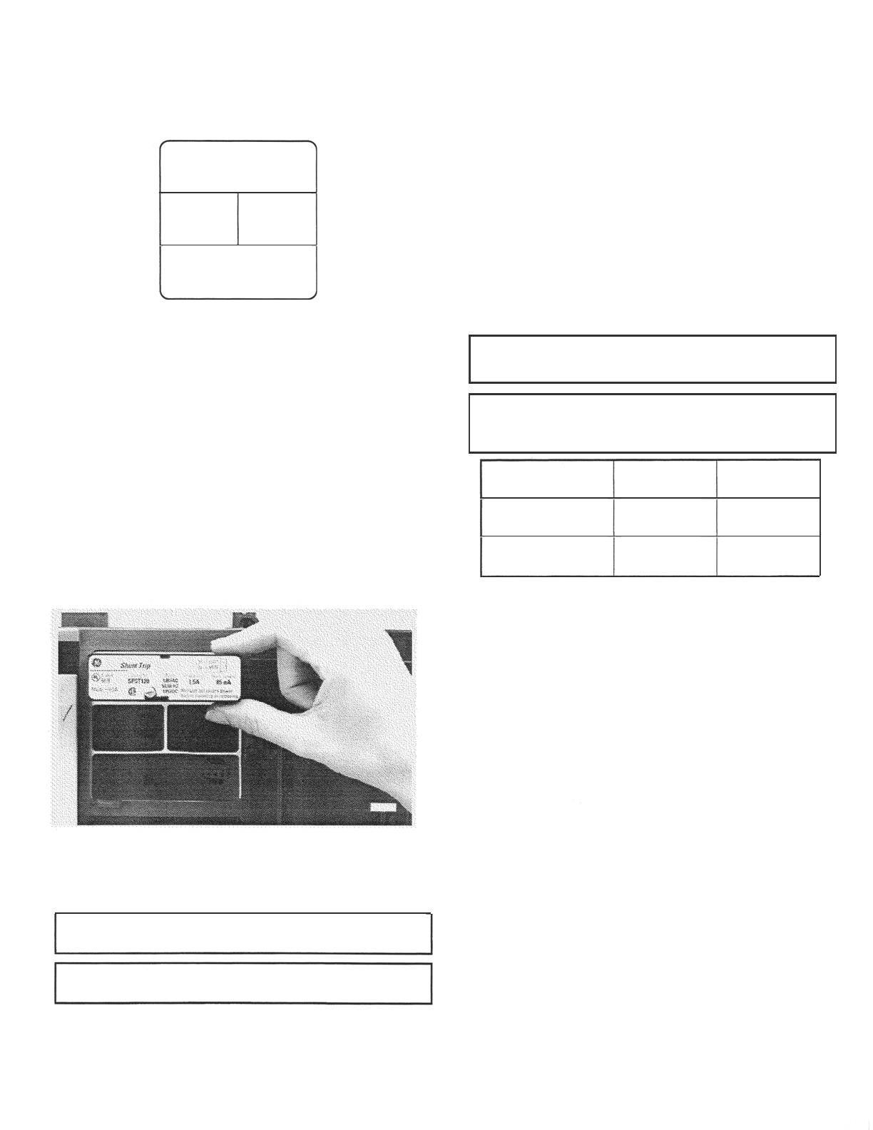
Ensure that the accessow is inserted in the correct slot, as in Figure
2, and that the label is upright.
Check that Shunt Trip control power is applied at greater than 55%
of the rated ac voltage. Check that the accessory is completely
inserted; reinsert if necessary.
Check for the proper voltage rating on the Shunt Trip.
Ensure that steps 6, 7, and 8 in the Installation section have been
followed correctly.
Check that the Shunt Trip accessory is completely inserted. Check
that the Trip Unit is seated correctly. If the Trip Unit was removed to
set the switches, check that it has been correctly installed; remove
and reinstall, if necessary.
Note that an otherwise underpowered Trip Unit would be powered
up by an energized Shunt Trip accessory.
Verify that the breaker is closed.
Check that the Shunt Trip with Lockout control power is applied at
greater than 55% of the rated ac voltage. Check that the accessory
is completely inserted; re-insert if necessary.
Note that an otherwise underpowered Trip Unit is powered by an
energized Shunt Trip accessory.
Check that the Shunt Trip with Lockout accessory is completely
inserted.
Check that the Shunt Trip or Shunt Trip with Lockout control
power has been removed.
Check that the breaker is not closed; if so, open it and try again.
Remove the Shunt Trip with Lockout accessory. If the lockout
plunger protrudes out of the accessory, replace the accessory. If the
plunger does not protrude, reinsert the accessory, ensuring good
alignment of the accessory in the pocket.
Wait at least 0.25 seconds before closing the breaker after removing
control power from the Shunt Trip.
Symptom
1SQC930034M0201, GEH6519 December 2019
—
ABB Inc.
305 Gregson Drive
Cary, NC 27511.
electrification.us.abb.com
—
We reserve the right to make technical
changes or modify the contents of this
document without prior notice. With
regard to purchase orders, the agreed
particulars shall prevail. ABB Inc. does not
accept any responsibility whatsoever for
potential errors or possible lack of
information in this document.
We reserve all rights in this document and
in the subject matter and illustrations
contained therein. Any reproduction or
utilization of its contents – in whole or in
parts – is forbidden without prior written
consent of ABB Inc.
Copyright© 2019 ABB
All rights reserved
—
GE is a trademark of GE. Manufactured
by ABB Inc. under license from GE.
6.
7.
8.
If a MicroVersaTrip Plus or MicroVersaTrip PM Trip Unit
is installed, check that the Trip Unit display is active
(powered).
Remove power from the Shunt Trip with Lockout.
Attempt to close the breaker; it should close as normal.
After the breaker has tripped and with the power still
applied to the Shunt Trip with Lockout, attempt to
close the breaker. The breaker should not close nor
attempt to close.
If a Shunt Trip with Lockout has been installed, continue
with the following steps:
5.
4
This manual suits for next models
3
Other ABB Circuit Breaker manuals

ABB
ABB AF40 User manual

ABB
ABB GE Power Break II GEH6271 User manual

ABB
ABB R-MAG User manual

ABB
ABB DEH41820 User manual

ABB
ABB VHK-R Installation and operating instructions

ABB
ABB SACE Tmax XT User manual

ABB
ABB SACE Emax 2 User manual

ABB
ABB VD4 Series Installation and operating instructions

ABB
ABB SACE Emax 2 - Tmax XT User manual

ABB
ABB Emax X1 B/E 1150 V User manual

ABB
ABB VM1-T User manual

ABB
ABB F200 B Service manual

ABB
ABB Tmax T7 Manual

ABB
ABB SACE Emax 2 User manual

ABB
ABB ADVAC User manual

ABB
ABB F-ARI Test Series User manual

ABB
ABB ADVAC Installation and operating instructions

ABB
ABB SACE Emax E1 User manual

ABB
ABB Sace Emax UL Listed Manual

ABB
ABB SACE Emax 2 User manual