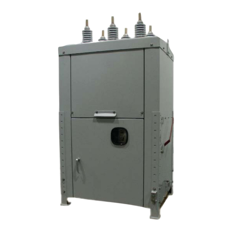
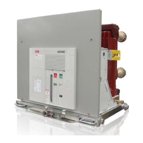
ABB FSK II S + Operating instructions

1. Disclaimer........................................................................................ 4
2. Introduction...................................................................................... 5
2.1. Improvement Policy................................................................. 5
2.2. Notice....................................................................................... 5
2.3. Standards and Regulations ..................................................... 5
3. Product Description ......................................................................... 6
3.1. Apparatus ................................................................................ 6
3.2. Identification........................................................................... 11
4. Safety Precautions ........................................................................ 13
4.1. Warning Notice...................................................................... 13
4.2. Personnel Requirements ....................................................... 13
5. Transport & Storage...................................................................... 14
5.1. Storage .................................................................................. 14
5.2. Transport ............................................................................... 15
5.3. Goods Acceptance and Visual Inspection............................. 15
5.4. Handling of transport damage ............................................... 15
6. Technical Data .............................................................................. 16
6.1. Electrical Data Pole ............................................................... 16
6.2. MABS Control Card ............................................................... 17
6.3. Weights and Dimensions....................................................... 23
6.4. Operating Conditions............................................................. 23
6.5. Torques for tightening screws and nuts................................. 23
6.6. Interfaces............................................................................... 23
7. Assembly & Commissioning.......................................................... 24
7.1. Unpacking the Material.......................................................... 24
7.2. Assembly / Installation........................................................... 24
7.3. Commissioning...................................................................... 27
8. Maintenance.................................................................................. 29
8.1. General.................................................................................. 29
8.2. Inspection .............................................................................. 29
9. Disposal......................................................................................... 32
10.Customer Service.......................................................................... 32
10.1. Procedure............................................................................ 32
10.2. Packaging ........................................................................... 32
10.3. Spare Parts ......................................................................... 33
11.Troubleshooting............................................................................. 33
12.Customer feedback file ................................................................. 35
ABB in the railways – Medium Voltage products
Product Family : FSK II S +
Operating and Maintenance Manual
2/36

3/36
Glossary
WD Watchdog function
MABS Magnetic Actuator for Breaker and Switch
Checksum Checksum of the MABS software
LBS Load break switch
CB Circuit Breaker
CPU Central processing unit (on electronics card)
BI Binary input
This symbol draws attention to specific technical information
DANGER!Non-observance of the activities or procedures identified with this
symbol can lead to personal injury!
IMPORTANT! Non-observance of the activities or procedures identified with this
symbol can lead to material damage!

4/36
1. Disclaimer
The information contained in this document can be modified without prior notification and is to be regarded as
non-binding. The document is in no way contractually binding and the content corresponds to the state of
technology at the time the document was prepared.
ABB SÉCHERON reserves the right to modify the product described in this document in the framework of further
technological developments or improvements.
Irrespective of any circumstances, the purchaser has the responsibility to obtain information about the
maintenance conditions and special operating requirements.
ABB SÉCHERON cannot accept any responsibility for damages which occur through non-observance or
incorrect interpretation of the information and regulations provided in this document.
This document may neither be duplicated in its entirety nor in extracts, without the prior consent of ABB
Sécheron. The transfer of the document or parts thereof to third parties is forbidden and will be prosecuted in
accordance with the statutory provisions.
ABB SÉCHERON reserves all rights, in particular those which result from its general terms of delivery.
©ABB

5/36
2. Introduction
The pictures and diagrams that are contained in this document are intended to illustrate this content and make it
as understandable as possible; they can differ from the contractual content of the materials
supplied through the use of different components and elements.
2.1. Improvement Policy
During the preparation of this document, we have placed special attention to understandability and
completeness.
It is our aim to continuously improve the quality of our documentation. We therefore welcome your opinion and
would be pleased if you would communicate suggestions for improvement to your local ABB or ABB Sécheron
representatives.
2.2. Notice
It is important that this document is stored in a safe place during the entire service life of the installation or
device; it should be passed on to any subsequent owners or operators. When ordering additional documentation,
please specify the corresponding reference number of the document, its revision and publication date.
2.3. Standards and Regulations
2.3.1. Device
The device conforms to the provisions of the following publications:
•EN 60694: Common Specifications for High-Voltage Switchgear
•EN 50152-1: Railway Applications; Fixed Installations – Particular Requirements for AC Switchgear -
Part 1: Single-Phase Circuit Breakers with Um above 1 kV
•EN 50152-2: Part 2
•EN 50124
•IEC 62271-100
2.3.2. Installation and Operation
For installation and operation, the corresponding pertinent provisions are to be taken into consideration, in
particular:
•HD 637: Power Installations exceeding 1 kV AC
•EN 50110-1: Operation of Electrical Installations
•Regulations for the prevention of accidents of the employer’s liability insurance associations or
comparable organisations
•Safety guidelines for auxiliary and operating materials
•Order-related specifications of ABB Sécheron

6/36
3. Product Description
3.1. Apparatus
The FSK IIS+ apparatus are designed for outdoor installations and used in 50/60Hz railway traction power supply
networks. They differ in particular by their fast breaking times.
The vacuum circuit-breaker and load break switch types are equipped with a modern magnetically actuated
mechanism instead of the conventional mechanical spring charged mechanism. The main insulators and the
orientation of the HV terminals can be configured according to the customer requirements.
Fig. 1 View of apparatus pole
Access for manual
tripping device (anti-
clockwise direction
of rotation)
Insulator (polymer)
Lower terminal
Upper terminal
Mounting plate
Drive unit
Identification plate
Cover panel
Fig. 2 Copper Connexion 1250A
Nickel-plated copper – EN CW004A
Connection’s range available1250 2500A
Fig. 3 Aluminium Connexion 2500A
En AW-5083
Connection’s range available 1250 2500A

7/36
Fig. 2 Apparatus drive unit, cover panel removed (shown only as an example)
Fig. 3 Control box, front panel removed (There may be project specific variation)
Magnetic actuator
Operations
counter
Mechanical
position indicator
Position sensors ON/OFF
Manual tripping catch
Heating resistance
Valve & protection for gas
filling Place for contact
wear check
Optional cable exit
Cable exit
Terminals
„
READY
“ indication
"ON"pushbutton
"
OFF
" pushbutton
MABS board
Capacitor bank
Control panel
Option : Capacitor
fast discharge
MABS support plate
This is a general view.
For project specific
views, with
descriptions, refer to
Appendix A, if any

8/36
The operation of the CB takes place by means of a modern magnetic actuator, which is driven by an electronic
MABS control card. The pulsed high-current energy for “Open” and “Close” operations (including a complete O-
CO sequence) is supplied by a capacitor bank. As a result, the auxiliary power supply of the installation is not
burdened by peak currents. Each actuator is equipped with two position sensors giving feedback on the state of
the pole. The MABS card analyses and indicates the state and consistency between expected sensor information
and given operating orders. The MABS card repeats this indication through auxilliary relays so that it is available
for external use.
3.1.1. MABS Control Card
Fig. 4 Schematic arrangement Drive/Controller (two-pole apparatus)
The apparatus can be controlled by local push-buttons or remote control signals. The MABS card permanently
monitors itself, the supply voltage, the magnetic actuator, the position sensors, the capacitor charge and the logic
of the breaker position against the switching instructions. Malfunctions are detected and signalled automatically.
An error-free state is indicated with the “READY“ signal. A set of dip switches and jumpers allows configuration
of the functionality, according to customer requests. These settings are factory set and not to be changed at a
later date without the agreement of ABB- Sécheron.
Main features in detail:
•High-power drive for magnetic actuator
•Capacitive energy storage (capacitor bank)
•Position sensors
•Push button panel
•7 binary inputs with universal voltage range
•7 binary outputs with universal voltage range
•LOCAL, REMOTE, GLOBAL operating modes (explanations in later chapters)
•Interlock functions (blocked in open)
•Under voltage aux. power supply detection
•System monitoring
•Power supply with two universal voltage ranges in AC/DC (depending on card type)
•Low stand-by power and limited charging power consumption
•Autonomy for apparatus operation in case of aux. power supply breakdown: T=1.5 to 2 min
Add
-
On card

9/36
Shown below is a schematic illustration of the MABS control card with the corresponding descriptions of the plug
connectors.
NO changes or manipulations to the card are to be performed without consultation with and confirmation
from ABB
Fig. 5 MABS Card layout (top view)
Plug connectors:
•KM1001 : Position sensors of the magnetic actuator
•KM1002 : Main power circuit of the magnetic actuator with capacitor bank link
•KM1003 : Auxiliary supply and capacitor supply
•KM1004 : Binary outputs
•KM1005 : Binary inputs
•KM1007 : Push buttons and READY LED
•Other unnamed plug connectors: not relevant or unused
3.1.2. Add-On Card
For bi-pole applications, an “Add-on” card is used to synchronise and handle the position information of two poles
and to check the consistency of their state. The position sensors of both poles are connected via this board to
the MABS card.
Figure 6 Add-On card for bi-pole application
KM1003 KM1005 KM1004 KM1007
KM1002 KM1001

10/36
Plug connectors:
•X1 : Position sensors of the magnetic actuator of Pole 1
•X2 : Position sensors of the magnetic actuator of Pole 2
•X3 : Connect to KM1001 of MABS
3.1.3. Control panel
A control panel is connected to the MABS control card and commands the CB locally by two pushbuttons. A
READY indicator LED is underneath the READY sign of the control panel and can be varied according to
specific customer requests, e.g the colour scheme of the push buttons.
Figure 7 (push button control panel)
3.1.4. Connector for portable power supply
For connection of a portable aux. power supply, a specific connector is accessible from the front cover panel.
Important!
Before connecting the portable power supply all other auxiliary power supply shall be disconnected or
deactivated. The rotative switch has to be in the service position.
Fig. 8 Front cover plate with dismounted cover of portable power connection
3.1.5. Mechanical position indication
A visual indication of the breaker open (green) or close (red) can be seen from ground level. This indication is
located under the breaker.
Green colour = apparatus open
Red colour = apparatus closed
Fig. 9 Mechanical indication
3.1.6. Manual opening from ground level (option)
A manual opening mechanism can be fitted onto the breaker. With the help of an isolating hook stick, the breaker
can be opened manually from ground level.

11/36
Fig. 10 Manual opening mechanism
3.1.7. Manual opening from pole level
To get access to the manual tripping catch, the threaded plug has to be removed. This can be done by means of
a coin or screwdriver. After removing the plug, the manual tripping crank can be introduced into the hole in the
front cover plate and the apparatus can be tripped by counter clockwise rotation of the hand crank.
Fig. 11 Manual opening mechanism
3.1.8. Electrical pole interlocking (option)
With this functionality which is mounted on the control box, the operation of the pole can be blocked either in the
“open” or “closed” position. If the lever is in the “service” position, normal operation is activated. If the lever is in
the “interlocked” position, no “remote” or “local” opening or closing operation will be executed. Both lever
positions can be locked by one or multiple padlocks.
Fig. 12 Electrical pole interlocking system
3.2. Identification
3.2.1. Apparatus

12/36
The identification plates are attached visibly to the pole & control box. The position and language can vary
depending on the customer requirements and the project. The extension of the Type descriptions with numbers
after the FSK designation are internal ABB descriptions and can vary from one apparatus to another.
Fig. 13 Example of Identification Plates in German, English & French
3.2.2. MABS Control Card
The identification of the electronic MABS card can be done by means of the number assigned to it as shown
below.
3.2.2.1. Codification Type « Barcode »
•aaaaaa= 751010 Fig. 14 Barcode sample
•bbbb= Version MABS (0811=FSK full LV, 0812=FSK full HV)
•cc= Year of manufacturing (05=2005 …99=2099)
•ddddd= Incremental manufacturing number
•ee= Manufacturer
•ff= Revision
•g= Barcode CRC (sum mode 10)
3.2.2.2. Identification of Software
The software version is identified by a sticker attached to the CPU and indicating the
checksum and date of the installed programm.
Fig. 15 Checksum

13/36
4. Safety Precautions
Danger!
Any apparatus which is damaged or defective must be switched off, disconnected from the power network and
secured in order to avoid unintentional operation before and during repair, which is to be performed by qualified
personnel.
4.1. Warning Notice
The following notices, if mentioned in the text, must be observed without fail.
Danger!
Non-observance of the activities or procedures identified by this symbol can lead to personal injury!
Important!
Non-observance of the activities or procedures identified by this symbol can lead to material damage!
4.2. Personnel Requirements
Danger!
This document describes the only official procedure approved by ABB Sécheron for performing the work
described. ABB Sécheron refuses all responsibility with non-observance of these procedures.
During all works, such as e.g. the detailed planning, installation, disassembly, maintenance and commissioning
of the apparatus, the persons performing the work are responsible for:
•The correct and proper functionally work planning
•The apparatus and the adjacent workplace
•All persons remaining in the work area
•The safety before restarting and reconnection
For the works specified above, the personnel performing the work must be qualified in accordance with local
valid regulations for this type of apparatus and demonstrate experience on similar types of devices. They must be
capable of reading the associated electrical diagram and cable lists and of working in accordance thereof. In
addition they should have a thorough knowledge of local safety regulations for electrical installations and control
systems.
All work on the electrical equipment of the apparatus itself may only be performed by suitably qualified personnel.
In accordance with standard EN 60204-1:1992 clause 3.55, a qualified person is:
•a person who demonstrates technical knowledge and experience, which enables him to recognise and
avoid risks and dangers that can be caused through electricity/chemical substances/mechanical
devices.
In accordance with standard EN 60204-1:1992 clause 3.30, a qualified person is:
•a person who is appropriately instructed, trained or supervised under qualified guidance, to recognise
and avoid risks and dangers that can be caused through electricity/chemical substances/mechanical
devices.

14/36
5. Transport & Storage
On delivery of the apparatus, its condition is to be examined for transport damage. If a defect is observed
(including damaged packaging), the manufacturer is to be informed immediately.
The apparatus is delivered in a vertical or horizontal position on a Euro pallet or in a special transport crate. With
vertical transport, the insulators are protected by a protective cover.
The apparatus must be transported with vacuum interrupter contacts in the open position
5.1. Storage
IMPORTANT!
During storage, the apparatus, accessories and spare parts must remain in their original packaging
Ensure that the apparatus, accessories and spare parts are stored in a dry and clean place, protected against
atmospheric influences such as dust, direct sunlight, humidity and condensation, as well as vibrations. Storage
conditions are to be observed in accordance with the specifications below.
In case of important temperature variations (∆T >30°C / 24h), long storage duration (>3month) and presence of
humidity, the resistances (in pole and control box) must be supplied to prevent condensation.
5.1.1. Apparatus Storage Temperatures
For the apparatus, general accessories and spare parts, a storage temperature of:
-40°C to +50°C is to be maintained. Before commissioning, completely bring the apparatus to operating
environment conditions (temperature and humidity).
5.1.2. Orientation
The apparatus has to be stored in the original packing and position.
5.1.3. MABS Control Card and Capacitors
Designation
Value
Period of storage without inspection 2 years
Formatting procedure
(every 2 years) Capacitors
Supply with Un for ~30 min. over a 1 kresistance, then
discharge.
MABS Control Card
Supply with Un for ~30 min., then discharge.
Storage temperature -40°C … +80°C
Relative humidity 0 …95% relative humidity (without condensation)

15/36
5.2. Transport
The apparatus and components may only be transported in the original packaging with suitable means of
transportation. Shocks and impacts, penetration of dust, liquids and moisture are to be prevented.
IMPORTANT!
The apparatus is susceptible to blows, in particular if equiped with ceramic insulators
To lift or move the apparatus, one should proceed as illustrated below. Blows to the insulators are to be
absolutely avoided. For weights and dimensions, please refer to a later chapter.
Fig. 16 Generally applicable transport of the apparatus
5.3. Goods Acceptance and Visual Inspection
After delivery of the component, it is recommended to carry out a visual inspection of the goods and to check:
•the correctness of the component
•for damages
•the conformity with the order, the identification plates, the identification numbers and the quantity of
components supplied.
With subsequent longer storage, the original packaging must be well re-sealed, in order to protect the apparatus
against environmental influences.
5.4. Handling of transport damage
In case of ABB Sécheron being responsible for transport, the customer is required to report any damage in
writing to ABB Sécheron within 7 days of receipt of the goods.
Damage reports are to be directed to the following addresses:
Your local ABB Agent
or
ABB Sécheron
(Address on the last page)

16/36
6. Technical Data
6.1. Electrical Data Pole
6.1.1. Load break switch & Circuit breaker FSK1025
Designation Value
Type: 1250
Frequency 50 Hz -60Hz
Operating voltage 25 kV
Number of phase 1 or 2
Rated voltage
acc. To EN 50124-1
acc. To EN 60694
27.5 kV
27.5 kV
Rated power frequency withstand voltage
Phase to earth
Across open contacts
Electromagnet, electronics and wiring to earth
(50Hz / 1 min)
105 kV
105 kV
2 kV
Rated lightning impulse withstand voltage
Phase to earth
Across open contacts
(1.2/50 µs)
250 kV
250 kV
Rated currents
Normal current
Short-circuit breaking current
Rated peak withstand current
Short circuit making current
Short time withstand current (3 s)
1250 A
8/25 kA
50/63 kA
50/63 kA
25 kA
Rated operating sequence
CB O – 0.3s – CO – 60s – CO
LBS CO
Closing time 65 ms
Opening time 45 ms
Strength of the circuit-breaker pole
- mechanical class M2=
- with maintenance
Operating cycles
10000
30000
Strength of the vacuum interrupter
Mechanical operating cycles
Electric power at rated current
Electric power at rated short-circuit break current
20000
20000
50

17/36
6.1.2. Circuit breaker FSK1025
Designation Value
Type: 2500
Frequency 50 Hz – 60Hz
Operating voltage 25 kV
Number of phase 1 or 2
Rated voltage
acc. To EN 50124-1
acc. To EN 60694
27.5 kV
27.5 kV
Rated power frequency withstand voltage
Phase to earth
Across open contacts
Electromagnet, electronics and wiring to earth
(50Hz / 1 min)
105 kV
105 kV
2 kV
Rated lightning impulse withstand voltage
Phase to earth
Across open contacts
(1.2/50 µs)
250 kV
250 kV
Rated currents
Normal current
Short-circuit breaking current
Rated peak withstand current
Short circuit making current
Short time withstand current (3 s)
2500 A
25 kA
63 kA
63 kA
25 kA
Rated operating sequence CB O – 0.3s – CO – 60s – CO
Closing time 65 ms
Opening time 45 ms
Strength of the circuit-breaker pole
mechanical class M2=
with maintenance
Operating cycles
10000
30000
Strength of the vacuum interrupter
Mechanical operating cycles
Electric power at rated current
Electric power at rated short-circuit break current
20000
20000
50
6.2. MABS Control Card
Specifications are valid for cards in revision from “Rev. 06“ onwards
A detailed description of the control card is provided in a separate operating manual and is available on
special request
6.2.1. Supply Voltages
“Low Voltage“ and ”High Voltage“ describe the two available supply voltage variants that exist for the MABS
control card.
Description Value Tolerance Frequency Insulation
Low Voltage 24…60 VDC -30%…+25% - Galvanic,
24…48 VAC -15%…+10% 50/60 Hz 2.5 kVrms
High Voltage 110…250 VDC -30%…+12% - Galvanic,
100…240 VAC -15%…+10% 50/60 Hz 2.5 kVrms
Table 1 Supply Voltage
6.2.2. Power Consumption
Power Consumption [W]
Continuous in static mode (nominal) 5-10
Maximum during the capacitor charging operation approx. 75
Table 2 Power Consumption

18/36
6.2.3. Binary Signal Inputs
The used binary inputs can differ from project to project. Please refer to the valid wiring diagram.
Designation Description Observation
Y1 Remote Close
Y2 Remote Open
Y3 Auxiliary Open & Hardware driven
safe Open Can be used in all operating modes (Global, Local,…)
Input can be set as HW SAFE-Open. If failure of the WD READY
– signal, here the apparatus can be switched off independently of
the state and condition of the CPU
Y4 Standard Open or Protective trip Input with extended voltage tolerance (see Table 4)
Y5 Selection:
-LOCAL/REMOTE
-LOCAL/GLOBAL (Remote/Local
switchover function)
LOCAL mode: only the use of local push buttons is accepted,
except input Y3 which is always active.
REMOTE mode: only remote control signals are accepted
GLOBAL mode: all signals are accepted
Y6 Lock in Open Locking of apparatus in the Open position
Y7 Under Voltage (Under voltage
function) Signal input for the detection of an undervoltage, variable voltage
values can be set
Table 3 Signal Inputs
6.2.4. Electrical Characteristics of the Signal Inputs
Designation Value
Voltage range 48 … 240 V
AC
/V
DC
Tolerance -15%…+10% tolerance
40.8…280 VDC
40.8…264 VAC
ONLY for Input Y4:
-30%…+10% tolerance
- 33.6…280 VDC (in standard input configuration)
- 12 VDC (in Protection trip configuration)
Input impedance 300 k
Input current < 2 mA @ 250 VAC/VDC
Table 4 Characteristics of the signal inputs
These represent the range of values the MABS card can accept. The specific voltage used still needs to be
selected via Dip switches as described later.

19/36
6.2.5. Binary Signal Outputs
The used binary inputs can differ from project to project. Please refer to the valid wiring diagram.
Designation Description Observation
S1 CB Open This output is a copy of the “OPEN” position as determined by the sensor
In the event of an error, the CPU activates the watchdog alarm
S2 CB Close This output is a copy of the “CLOSE” position as determined by the sensor
In the event of an error, the CPU activates the watchdog alarm.
S3 Aux. CB Open This output is a copy of the “OPEN” position as determined by the sensor
S4 Aux. CB Close This output is a copy of the “CLOSE” position as determined by the sensor
S5 Unit Ready Standby indicator for:
•Correct capacitor charge
•Coil continuity
•Valid and coherent position indication
•<10 faulty switching attempts
S6 WD Ready Self-monitoring signal of CPU – readiness
Closed when:
•WD in NOT READY = CPU is not working properly or MABS not supplied
Open when:
•MABS is supplied AND CPU is working
S7 Undervoltage detection Display of the input Y7 with 100 ms response delay
Closed when:
•Under voltage is low (active) = voltage failure
Open when:
•Under voltage is high = voltage correct
Table 5 Signal Outputs

20/36
6.2.6. Electrical Characteristics of the Signal Outputs
The outputs all consists of voltage free contacts with the following properties:
Designation Value
Voltage range 0 ... 280 VDC
0 ... 264 V
AC
Max. switching capacitance <6A, 250 VAC (ohmic)
Max. making/breaking capacity <1500 VA/ DC
Max. switching voltage <400 VAC, 300 VDC
Max. contact resistance <100 m
Max. switching times <5 ms
Table 6 Characteristics of the signal outputs
6.2.7. Output relay states
The following table indicates the state of the available output relays, S1 to S7
Capacitors discharged / No
power supply Apparatus closed and
supplied FSK-II S+ open and supplied
S1 — — (open) — — — — — (closed)
S2 — — — — — — —
S3 — — — — — — —
S4 — — — — — — —
S5 — — — — — — — —
S6 — — — — — — — — —
S7 — — — — — — —
Table 7 States of output relays
6.2.8. Dip Switches and their function
The position of the dip-switches should only be read after disconnecting the power supply with subsequent
complete discharge of capacitors. Setting the dip-switches is only to be performed with the power supply
disconnected and capacitors completely discharged.
Danger! Important!
6.2.8.1. I1001 Undervoltage threshold
With this switch, the threshold value of the undervoltage trip is set.
Dip Switch I1001
Nominal Voltage
[Un] Tolerance Range
[35% Unmax and
70% Unmin]1 2 3
ON
OFF X X X
220…240 VAC/DC 84.0 … 154.0 VAC/DC
ON X
OFF X X
100…127 VAC/DC 44.45 … 70.0 VAC/DC
ON X
OFF X X
60 VDC 21.0 … 42.0 VDC
ON X
OFF X X
48 VDC 6.8 … 33.6 VDC
Table 8 Dip Switch I1001
Table of contents
Other ABB Circuit Breaker manuals