manuals.online logo
Brands
  1. Home
  2. •
  3. Brands
  4. •
  5. ABB
  6. •
  7. Circuit Breaker
  8. •
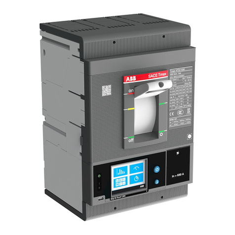
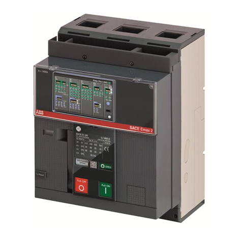
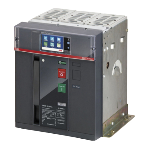
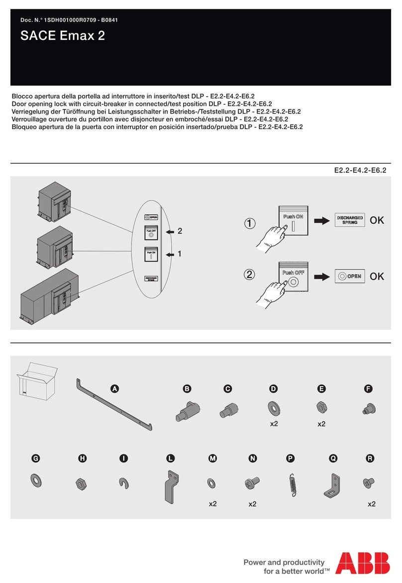
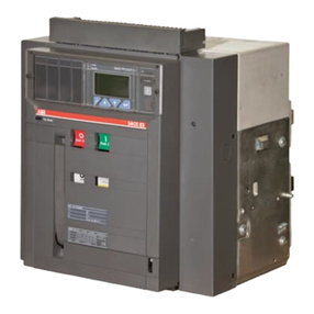
  9. ABB SACE Emax 2 E2.2 User manual

ABB SACE Emax 2 E2.2 User manual

(1)
DOC. N.° 1SDH001612R0001 - B1542
Direct replacement Masterpact / Emax 2
Retrofitting tra interruttori Emax 2 E2.2 e Masterpact M08 ÷ M25
Retrofitting between Emax 2 E2.2 and Masterpact M08 ÷ M25
Retrofit zwischen Leistungsschaltern Emax 2 E2.2 und Masterpact M08 ÷ M25
Retrofitting entre disjoncteurs Emax 2 E2.2 et Masterpact M08 ÷ M25
Retrofit entre interruptores automáticos Emax 2 E2.2 y Masterpact M08 ÷ M25
Il presente kit di retrofitting è
studiato per la sostituzione di
interruttori aperti Masterpact
M08-M25.
Essi consentono di inserire nella
parte fissa Masterpact un
interruttore Emax 2 di medesima
taglia in accordo a quanto
indicato in tabella A.
This retrofit kit has been
designed for replacing
Masterpact M08-M25 air circuit-
breakers.
It allows an Emax 2 circuit-
breaker of the same size to be
racked into the fixed part of
Masterpact as indicated in table
A.
Dieser Nachrüstsatz ist für den
Austausch der offenen
Leistungsschalter Masterpact
M08-M25. Sie gestatten es, in
den festen Teil des Masterpact
einen Leistungsschalter Emax 2
der gleichen Baugröße
einzuschieben, so wie es in der
Tabelle A angegeben ist.
Le présent kit de «retrofitting»,
est conçu pour la reconfiguration
de disjoncteurs ouverts
Masterpact M08-M25. Ils
permettent d'introduire dans la
partie fixe Masterpact un
disjoncteur Emax 2 de même
taille conformément à ce qui est
indiqué dans le tableau A.
El presente kit de retrofit ha sido
estudiado para la sustitución de
interruptores abierto Masterpact
M08-M25. Los mismos permiten
introducir en la parte fija
Masterpact un interruptor Emax2
del mismo tamaño, de
conformidad con lo indicado en
la tabla A.
ATTENZIONE!
Le istruzioni del presente kit di
retrofitting si riferiscono
all’interruttore in esecuzione per
manovre di inserzione ed
estrazione a porta del quadro
chiusa.
ATTENTION!
The instructions in this retrofit kit
refer to circuit-breakers designed
for racking in/out operations with
the switchgear door closed.
ACHTUNG!
Die Anweisungen dieses
Nachrüstsatzes beziehen sich
auf den Leistungsschalter in
Ausführung zum Einfahren und
Ausfahren bei geschlossener
Schaltfeldtür.
ATTENTION!
Les instructions du présent kit de
reconfiguration se réfèrent à la
version de disjoncteur pour
manœuvres d'embrochage et de
débrochage avec porte du
tableau fermé.
ATENCIÓN
Las instrucciones del presente
kit de retrofit se refieren al
interruptor en ejecución para
maniobras de inserción y
extracción con la puerta del
cuadro cerrada.
(**) = Derating fino a 2300A con parte fissa e terminali HR; nessun derating con parte fissa e terminali VR
(**) = Derating up to 2300A with Fixed part with HR terminals; no derating with Fixed part with VR terminals
(**) = Deratings bis zu 2300A mit festem Teil und Anschlüssen HR; kein Derating mit festem Teil und Anschlüssen VR
(**) = Déclassement jusqu'à 2300A avec partie fixe et prises HR; aucun déclassement avec partie fixe et prises VR
(**) = Reducción de potencia (derating) hasta 2300A con parte fija y terminales HR; ninguna reducción con parte fija y
terrminales VR
Tabella A - Table A - Tabelle A - Tableau A - Tabla A
E' garantita la totale
corrispondenza delle
caratteristiche elettriche
(corrente nominale, esclusi
derating evidenziati in tabella, e
potere di interruzione) a
condizione che:
1.La scelta sia effettuata in
conformità a quanto riportato nei
cataloghi tecnici ABB relativi ai
prodotti di retrofitting.
2.L'interruttore Masterpact M da
sostituire sia stato installato in
conformità al proprio manuale di
installazione,rispettando le
distanze di
isolamento verso massa, il
dimensionamento delle sbarre di
connessione, il posizionamento
del primo setto di ancoraggio.
Tale kit è stato studiato altresì per
poter preservare le funzionalità
dei circuiti ausiliari e le manovre
di inserzione ed estrazione del
vecchio interruttore, senza dover
eseguire alcuna modifica alle
parti attive del quadro.
It is guaranteed the total
matching of the electrical
characteristics (rated current,
excluding derating indicated in
the table, and breaking capacity)
so long as:
1.The kit is chosen in
accordance with the indications
in the ABB technical catalogues
dedicated to retrofitting
products.
2.The Masterpact M circuit-
breaker to be replaced has been
installed in accordance with the
instructions in the relative
installation manual and in
compliance with the required
clearances to earth, size of the
connection busbars and position
of the first anchor plate.
Such kit have been designed
also to preserve the auxiliary
circuits and insertion/extraction
operations functionality of the old
circuit breaker, without the need
of any modifications on the
switchgear active parts.
Die völlige Übereinstimmung der
elektrischen Eigenschaften
(Bemessungsstrom,
ausgenommen der in der Tabelle
stehenden Derating-Werte, und
Ausschaltvermögen) ist unter
den folgenden Voraussetzungen
garantiert:
1.Die Wahl wird gemäß den
Angaben getroffen, die in den
technischen ABB-Katalogen zu
den Retrofitting-Produkten steht.
2.Der zu ersetzende
Leistungsschalter Masterpact M
ist gemäß dem eigenen
Installations-Handbuch unter
Einhaltung der Isolierstrecken
gegen Masse, der
Dimensionierung der
Verbindungsschienen und der
Positionierung der ersten
Verankerungspatte installiert
worden.
Dieser Bausatz ist ferner so
konzipiert, dass die Funktionen
der Hilfsstromkreise und die
Einschieb- und Ausfahrvorgänge
des alten Schalters beibehalten
werden können, ohne dass
Änderungen an den aktiven
Teilen der Schaltanlage
erforderlich sind.
La correspondance totale des
caractéristiques électriques est
garantie (courant assigné, en
excluant les déclassements mis
en évidence dans le tableau, et
pouvoir de coupure) à condition
que:
1. Le choix soit effectué
conformément aux catalogues
techniques ABB relatifs aux
produits de reconfiguration.
2. Le disjoncteur Masterpact M à
remplacer ait été installé
conformément à son manuel
d’installation, en respectant les
distances
d’isolation vers la masse, le
dimensionnement des barres de
connexion, le positionnement du
premier diaphragme d’ancrage.
Ce kit a également été étudié
pour pouvoir préserver les
fonctions des circuits auxiliaires
et les manœuvres d'embrochage
et de débrochage de l'ancien
disjoncteur, sans devoir effectuer
aucune modification des parties
actives du tableau.
Está garantizada la congruencia
total con las características
eléctricas (corriente asignada,
excluidos los declasamientos
evidenciados en la tabla, y poder
de corte) siempre que:
1.La selección se efectúe de
conformidad con lo expuesto en
los catálogos técnicos ABB
relativos a los productos de
retrofitting.
2.El interruptor Masterpact M a
sustituir haya sido instalado de
conformidad con el respectivo
manual de instalación,
respetando las distancias de
aislamiento hacia masa, el
dimensionamiento de las barras
de conexión, el posicionamiento
del primer tabique de anclaje.
El kit mantiene inalterados el
funcionamiento de los circuitos
auxiliares y las maniobras de
inserción y extracción quese
realizaban con el antiguo
interruptor, sin necesidad de
hacer modificaciones en las
partes activas del cuadro.
Masterpact taglia Emax 2 taglia Note
M08 - N1 800A E2.2 (N) 800A
M08 - H1 800A E2.2 (N) 800A
M10 - N1 1000A E2.2 (N) 1000A
M10 - H1 1000A E2.2 (N) 1000A
M12 - N1 1250A E2.2 (N) 1250A
M12 - H1 1250A E2.2 (N) 1250A
M16 - N1 1600A E2.2 (B) 1600A
M16 - H1 1600A E2.2 (N) 1600A
M20 - N1 2000A E2.2 (N-S) 2000A
M20 - H1 2000A E2.2 (H) 2000A
M25 - N1 2500A E2.2 (N-S) 2500A **
M25 - H1 2500A E2.2 (H) 2500A **
(2)
IMPORTANTE!
L'attività di retrofitting consente
una sostituzione di un dispositivo
di comando e protezione
divenuto obsoleto senza alterare
i dati di progetto originali del
quadro esistente. Qualora il
nuovo interruttore presentasse
dati di targa superiori, i kit di
retrofitting sono dimensionati e
certificati per le prestazioni del
vecchio dispositivo.
Per ulteriori chiarimenti
contattare ABB.
IMPORTANT!
Retrofitting allows an obsolete
control and protection device to
be replaced without altering the
original design data of the
existing switchgear. In the case
of the new circuit breaker with
major rated data values, the
retrofitting kits are dimensioned
and certificated for the old device
perfomances.
For any further question please
contact ABB.
WICHTIG!
Die Nachrüstung gestattet das
Austauschen einer überholten
Schalt- und Schutzeinrichtung,
ohne die ursprünglichen
Projektdaten der vorhandenen
Schaltanlage zu verändern. Auch
wenn der neue Schalter höhere
Kenndaten aufweisen sollte, sind
die Retrofit-Bausätze für die
Kenndaten des alten
Schaltgeräts dimensioniert.
Für weitere Informationen ABB
kontaktieren.
IMPORTANT!
L'activité de mise à niveau
permet la reconfiguration ou
remplacement d’un dispositif de
commande et de protection
devenu obsolète sans altérer en
aucune manière les données
d’origine de projet du tableau
existant. Dans le cas où le
nouveau disjoncteur présenterait
des données de plaque
signalétique supérieures, les kits
de retrofitting seront
dimensionnés pour offrir les
performances de l'ancien
dispositif. Pour tout complément
d'information, contacter ABB.
IMPORTANTE!
Las operaciones de retrofit
permiten una sustitución de un
dispositivo de mando y
protección ya obsoleto sin
alterar los datos de diseño
originales del cuadro existente.
Si el nuevo interruptor
automático tiene valores
asignados superiores a los del
antiguo, tras el montaje en
retrofit adquiere
automáticamente los del
dispositivo anterior. Para más
información, contactar con ABB
Sace.
Viene garantito il corretto
funzionamento del kit di
retrofitting a condizione che la
parte fissa Masterpact sia
completamente integra.
Vedi 1SDH001279R0001.
The retrofitting kit is guaranteed
to operate properly only if the
Masterpact fixed part is fully
intact.
See 1SDH001279R0002.
Der korrekte Betrieb des
Nachrüstsatzes wird nur
gewährleistet, sofern das feste
Teil Masterpact vollkommen
intakt ist.
Siehe 1SDH001279R0003.
Le fonctionnement du kit de
reconfiguration est garanti à
condition que la partie fixe
Masterpact soit en parfait état.
Voir 1SDH001279R0004.
Se garantiza el funcionamiento
correcto del kit de retrofitting
siempre y cuando la parte fija
Masterpact esté completamente
íntegra.
Ver 1SDH001279R0005.
MESSA IN SICUREZZA
DELL'IMPIANTO
A) A garanzia dell'incolumità del
personale addetto
all'installazione del kit, prima di
operare la sostituzione
dell'interruttore, si raccomanda
di eseguire scrupolosamente le
seguenti azioni:
- Mettere fuori servizio il quadro
ospitante;
- Portare l'interruttore da
sostituire in posizione di aperto e
molle scariche.
- Prima di estrarre l'interruttore,
controllare nuovamente il fuori
servizio dell'utenza.
B) Estrarre il vecchio interruttore.
C) Verificare che l’interruttore da
sostituire sia installato
rispettando le minime distanze di
isolamento verso le pareti,
indicate sul manuale Masterpact
M e riportate nella tab.1 di
questo manuale.
Per maggiori informazioni fare
riferimento al documento
RH0100004 “Istruzioni per
l'installazione e la manutenzione”
SETTING THE INSTALLATION
IN SAFE CONDITIONS
A) To ensure that the persons
who install the kit work in safe
conditions, strictly comply with
the following instructions before
replacing the circuit-breaker.
- Close down the switchboard in
which the circuit-breaker is to be
installed.
- Set the old circuit-breaker to
the open position with the
springs unloaded.
- Check to make sure that the
user is disconnected before
removing the circuit-breaker.
B) Remove the old circuit-
breaker.
C) Make sure that the replaced
circuit-breaker is installed in
accordance with the minimum
clearances towards walls, as
indicated in the Masterpact M
manual and in tab.1 of this
manual.
Consult document RH0100004
“Installation and maintenance
instructions” for further details.
SICHERUNGDER ANLAGE
A) Zur Gewährleistung der
sicherheit des für den einbau
des Bausatzes zuständigen
personals müssenunbedingt vor
dem Auswechseln des schalters
die folgenden Tätigkeiten
gewissenhaft ausgeführt werden:
- Die Schaltanlage außer betrieb
setzen,bei der austausch
vorgenommen werden soll.
- Den auszutauschenden
schalter in die AUS- stellung mit
entspannten einschalt federn
schalten.
- Vor dem Ausfahren des
schalters erneut sicherstellen,
dass alle betriebsmittel außer
betrieb sind.
B) Den alten Leistungsschalter
ausfahren.
C) Sicherstellen, dass der zu
ersetzende Leistungsschalter
unter Einhaltung der
Mindestisolierstrecken zu den
Wänden installiert worden ist, die
im Handbuch Masterpact M
angegeben sind und in der Tab.1
dieses Handbuchs stehen.
Für weitere Informationen Bezug
auf das Dokument RH0100004
“Installations- und
Wartungsanweisungen” nehmen.
MISE EN SÉCURITÉ DE
L'INSTALLATION
A) Afin de garantir la sécurité du
personnel chargé de l'installation
du kit, avant de procéder au
remplacement du disjoncteur, il
est recommandé d'effectuer
scrupuleusement les opérations
suivantes:
- Mettre hors service le tableau
où sera effectuè le
remplacement.
- Mettre le disjoncteur à
remplacer en position ouvert,
ressorts désarmés.
- Avant de dèbrocher le
disjoncteur contrôler de nouveau
que toutes les utilisations
possibles on tété mises hors
service.
B) Extraire l’ancien disjoncteur.
C) Vérifier que le disjoncteur à
remplacer soit mis en place en
respectant les distances
minimum d’isolement vers les
parois, indiquées sur le manuel
Masterpact M et indiqué dans le
tab. 1 de ce manuel.
Pour plus d'informations faire
référence au document
RH0100004 “Instructions pour
l'installation et la maintenance”.
SEGURIDAD DE LA
INSTALACIÒN
A) Para garantizar la seguridad
del instalador, antes de sustituir
el interruptor automático,se
recomienda efectuar
rigurosamente las siguientes
operaciones:
- Poner fuera de servicio el
cuadro donde se va a realizar la
sustitución.
- Poner el interruptor automático
que se va a sustituir en posición
de abierto con los resortes
descargados.
- Antes de extraer el interruptor
automático, asegurarse de que
todos los suministros de
corriente al interruptor esténdes
disactivados.
B) Extraer el viejo interruptor.
C) Verificar que el interruptor a
sustituir haya sido instalado
respetando las distancias de
aislamiento mínimas hacia las
paredes, indicadas en el manual
Masterpact M y expuestas en la
tab.1 de este manual.
Para más información consultar
el documento RH0100004
“Instrucciones para la instalación
y el mantenimiento”.
IMPORTANTE
Attenzione Istruzioni riguardanti il
solo assemblaggio del kit di
retrotitting,
non sono da intendersi come
sostitutive del manuale di
installazione, uso e
manutenzione del nuovo
interruttore Emax 2.
Verificare la possibilità di cablare
i circuiti ausiliari del vecchio
interruttore con
il nuovo e confrontarne la
compatibilità secondo lo schema
elettrico di
equivalenza
n°1SDM000106R0001 allegato al
kit
WARNING
The instructions concern the
sole assembly of the retrofitting
kit.
They do not substitute the
instructions in the installation,
operation and
maintenance manual of the new
Emax 2 circuit-breaker. Make
sure that the
auxiliary circuits of the old circuit-
breaker can be wired to the new
one and that
the components are compatible,
by checking the equivalent
wiring diagram
N°1SDM000106R0001 enclosed
with the kit.
ACHTUNG
Anweisungen, die sich lediglich
auf den
Einbau des Nachrüstsatzes
beziehen und nicht so
zu verstehen sind, dass sie die
Installations-,
Betriebs- und
Wartungsanleitungen des neuen
Leistungsschalters Emax
ersetzen. Prüfen, ob die
Möglichkeit besteht, die
Hilfsstromkreise des alten
Leistungsschalters mit dem
neuen zu verdrahten
und die Kompatibilität nach dem
Gleichwertigkeits-
Schaltbild Nr.
1SDM000106R0001 prüfen, das
dem Nachrüstsatz beiliegt.
ATTENTION
Ces instructions concernent
uniquement
l’assemblage du kit de «
retrofitting », elles ne
remplacent en aucun cas celles
du manuel
d’installation, utilisation et
entretien du nouveau
disjoncteur Emax 2. Vérifier la
possibilité de câbler
les circuits auxiliaires de l’ancien
disjoncteur avec
le nouveau et comparer la
compatibilité d’après le
s c h é m a é l e c t r i q u e d ’ é
q u i v a l e n c e
n°1SDM000106R0001 annexé au
kit.
ATENCION
Instrucciones relativas
exclusivamente
al ensamblado del kit di
retrotitting. Estas
instruciones no sustituyen
aquellas presentes en el
manual de instalación, uso y
mantenimiento del
nuevo interruptor Emax 2.
Verificar la posibilidad de
cablear los circuitos auxiliares
del viejo interruptor
con el nuevo y verificar su
compatibilidad según el
esquema eléctrico
n°1SDM000106R0001
anexado al kit.
(3)
1
Q.ty
1
1
1
2
2
A
B
D1 D2
E1 E2
F2
G
1 + 1
1 + 1
C
H
I
J
Q.ty
F1
1 + 1
2
M6x12
4
M6x50
M8x20
4
6
Ø5
Ø5
Ø8.4
Ø10.5
Ø8.4
Ø10.5
M10x25
M5x14
4
2
4
6
1
4
12
1
M5
M8
M10
4
12
1
K
L
M
N
O
P
Q
R
S
U
V
W
X
Y
Ø6.4
4
T
M8x25 O1
M8 Y1
(4)
Estrazione parte mobile da
sostituire con il kit di retrofitting
Emax 2 E2.2.
- Prima di eseguire qualsiasi
manovra verificare che la parte
mobile Masterpact sia aperta e
con le molle scariche.
- Se presente premere il pulsante
di sblocco all’estrazione e
ruotare la manovella fino alla
posizione di estratto.
- Sollevare la parte mobile,
preferibilmente mediante
l’apposito carrello.
Removal of the moving part to be
replaced with the Emax 2 E2.2
retrofit kit.
- Prior to performing any
operation, make sure that the
Masterpact moving part is open
and that the springs are
discharged.
- If present, press the withdrawal
release button and turn the
handle to the withdrawn position.
- Lift the moving part, preferably
using the purpose-made truck.
Ausfahren des zu ersetzenden
beweglichen Teils mit dem
Retrofitting-Kit Emax 2 E2.2.
- Vor jeglichem Eingriff
sicherstellen, dass das
bewegliche Teil von Masterpact
ausgeschaltet ist und entspannte
Schaltfedern hat.
- Sofern vorhanden, die Taste
zum Entriegeln für das Ausfahren
drücken und die Handkurbel bis
zum Erreichen der Außenstellung
drehen.
- Das bewegliche Teil heben,
möglichst mit den
entsprechenden Wagen.
Extraction de la partie mobile à
remplacer avec le kit de
reconfiguration Emax 2 E2.2.
- Avant d’effectuer une
quelconque opération vérifier
que la partie mobile Masterpact
est dans la position ouverte et
avec les ressorts débandés.
- Si prévu, appuyer sur le
bouton-poussoir de déblocage
au débrochage et tourner la
manivelle jusqu’à la position de
débroché.
- Soulever la partie mobile, de
préférence avec le chariot prévu
à cet effet.
Extracción de la parte móvil a
sustituir con el kit de retrofitting
Emax 2 E2.2.
- Antes de efectuar cualquier
maniobra, verificar que la parte
móvil Masterpact esté abierta y
con los resortes descargados.
- Apretar el pulsador de
desbloqueo para la extracción
(si está previsto) y girar la
manivela a la posición de
extraído.
- Levantar la parte móvil, en lo
posible utilizando el
correspondiente carro.
1
(5)
Estratto del manuale di installazione e manutenzione interruttore Masterpact ed Emax 2.
Extract from the installation and maintenance manual of the Emax 2 circuit-breaker.
Auszug aus dem Installations- und Wartungshandbuch des Leistungsschalters Emax 2.
Extrait du manuel d’installation et d’entretien du disjoncteur Emax 2.
Extracto del manual de instalación y mantenimiento interruptor Emax 2.
Dimensioni della cella. La tabella sottostante riporta le dimensioni esterne di una cella interruttore per installazione in un quadro B.T.
Compartment dimensions. The table below gives the external dimensions of a circuit-breaker compartment for installation in an L.V. switchboard.
Abmessungen des Schaltfelds. Die folgende Tabelle zeigt die Außenabmessungen einer Leistungsschalterzelle für die Installation in einer NS-Schaltanlage.
Dimensions du compartiment. Le tableau ci-dessous reporte les dimensions extérieures d’un compartiment disjoncteur pour le montage dans un tableau B.T.
Dimensión de la celda. La tabla de aquí abajo expone las dimensiones externas de una celda interruptor para instalación en un cuadro B.T.
B
A
B
Masterpact M08 to M25
type of connection to insulated barrier
A B
front connection without cover
300 15
rear connection without cover 150 15
rear connection with cover 0 0
B
A1
B
Kit DR Emax 2 E2.2
type of connection to insulated barrier
front connection without cover
264 15
rear connection without cover 114 15
rear connection with cover 20 15
A1 B
435
439475
70 55
425
55
325
55
435 (3p)
550 (4p) 550 (4p)
X+2
0
439
MASTERPACT M08 ÷ M25 KIT DR EMAX 2 E2.2
475
X+2
0
TAB. N°1
(6)
B) Forare portella quadro
secondo necessità del nuovo
interruttore.
B) Make a hole in the
switchboard door, as necessary.
B) Die erforderlichen Bohrungen
und den ausschnitt in der
Schaltfeldtür nach Bedarf
realisieren.
B) Percer la porte du tableau
selon les besoins.
B) Taladrar la tapa del cuadro
según necesidad.
C) Collocare la dima adesiva alla
portella e controllare che la linea
tratteggiata sia perfettamente
corrispondente con li foro già
presente sulla portella.
C) Position the adhesive
template on the door and make
sure that the dotted line perfectly
matches the aperture on the
door itself.
C) Die Klebeschablone an der
Klappe anbringen und
sicherstellen, dass die
gestrichelte Linie ganz mit den
Loch übereinstimmt, das schon
auf der Klappe vorhanden ist.
C) Placer le gabarit adhésif à la
porte et vérifier que la ligne
hachurée coïncide parfaitement
avec l’ouverture présente sur la
porte.
C) Colocar la plantilla adhesiva
en la puerta y controlar que la
línea punteada coincida
perfectamente con el agujero ya
presente en la puerta.
A) Smontare la mascherina
dell’interruttore obsoleto.
A)Dismantle the front plate of the
circuit breaker.
A) Den abdeckrahmen vom alten
schalter montieren.
A) Démonter la garniture de
l'ancien disjoncteur.
A) Desmontar el marco del
antiguo interruptor automático.
- Asse foratura porta
- Door aperture axis
- Bohrachse der Tur
- Axe perçage porte
- Eje perforacion puerta
- Base appoggio interruttore
- Circuit-breaker’s bearing base
- Abstellfläche des leistungsschalters
- Base d'appui disjoncteur
- Base apoyo interruptor
- Asse verticale
- Vertical axis
- Vertikale Achse
- Axe vertical
- Eje vertical
X
X [mm]
Masterpact 201
Emax 2 230,5
Fig. 1
Fig. 2
Fig. 3
2
G
(7)
D) Tagliare la portella seguendo
la linea continua rossa e forare
secondo i fori blu.
D) Cut the door along the
continuous red line and make
the holes in line with the red
hole.
D) Den schnitt in der
Schaltfeldtür entlang der roten
Linie und die Bohrungen bei den
roten Kreisen ausführen.
D) Couper la porte en suivant la
ligne continue rouge et percer
selon les trousrouges.
D) Cortar la tapa a lo largo de la
línea continua roja y perforar
donde se encuentran los puntos
rojos.
E) Se la linea tratteggiata della
dima adesiva non è
perfettamente combaciante con
la foratura già presente nella
portella, effettuare il taglio di una
nuova portella come indicato
secondo il posizionamento degli
assi (X-Y) della mascherina.
E) If the dotted line on the
adhesive template fails to
perfectly match the existing
opening in the door, cut a new
door as indicated by the
positions of the axes (X-Y) on the
template.
E) Wenn die gestrichelte Linie
der Klebeschablone nicht perfekt
mit den Bohrlöchern
zusammenfällt, die schon auf der
Schaltfeldtür vorhanden sind, die
Bohrung einer neuen
Schaltfeldtür so ausführen, wie
es nach der Positionierung der
Achsen (X-Y) der Schablone
angegeben ist.
E) Si la ligne hachurée du
gabarit adhésif ne coïncide pas
parfaitement avec le perçage
présent sur la porte, effectuer la
découpe d'une nouvelle porte,
comme indiqué, suivant le
positionnement des axes (X-Y)
de la garniture.
E) Si la línea punteada de la
plantilla adhesiva no coincide
perfectamente con el taladrado
ya presente en la portezuela,
efectuar el corte de una nueva
portezuela como está indicado,
según el posicionamiento de los
ejes (X-Y) de la plantilla.
- Tagliare/forare secondo l’adesivo rosso/blu.
- Cut as show by the red adhesive material.
- Nach dem roten Aufkieber schneiden.
- Decouper suivant l’adhesif rouge.
- Cortar siguiendo el adhesivo rojo.
306
153
Ø5 n°14 holes
374
158
100
192
50
384
100
100
100 100
Fig. 5
Fig. 4
3 x Ø 4.5 mm
(8)
F) Montare l’adattatore della portella e la mostrina antipolvere della porta della cella.
Assemble the door adapter and the dust-guard flange of the compartement door.
Den Türadapter montieren und staubschutzrahmen der Schaltfeldtür.
Monter l’adaptateur de la porte et le guarniture anti-poussière de la porte du compartimient.
Montar el adaptador de la puerta y el marco antipolvo de la puerta de la celda.
FOR EMAX 2 E2.2 WITH MASTERPACT M08 ÷ M25
1 Nm
Fig. 6
2 Nm
F2
F1
(9)
3
A) Smontare i contatti striscianti
della parte fissa Masterpact.
A) Disassemble the sliding
contacts of the Masterpact fixed
part.
A) Die Gleitkontakte des festen
Teils von Masterpact ausbauen.
A) Démonter les contacts
glissant de la partie fixe
Masterpact.
A) Desmontar los contactos
deslizantes de la parte fija
Masterpact.
Fig. 7
(10)
B) Smontare il frontale e la sede
della manovella della parte fissa
Masterpact.
B) Remove the front panel and
the seat of the handle of the
Masterpact fixed part.
B) Den Frontteil und den Sitz der
Handkurbel des festen Teils von
Masterpact ausbauen.
B) Démonter la partie frontale et
le logement de la manivelle de la
partie fixe Masterpact.
B) Desmontar el frontal y el
alojamiento de la manivela de la
parte fija Masterpact.
Fig. 8
(11)
2
1
3
3
Z
C) Smontare le guide di
inserzione della parte fissa
Masterpact.
C) Disassemble the racking-in
guideways of the Masterpact
fixed part.
C) Die Führungen zum Einfahren
des festen Teils von Masterpact
ausbauen.
C) Démonter les glissière
d’introduction de la partie fixe
Masterpact.
C) Desmontar las guías de
inserción de la parte fija
Masterpact.
Fig. 9
To be reused!
(12)
2
1
1
D) Rimuovere il perno
antirorazione della parte fissa
Masterpact.
D) Remove the locking pin of
the Masterpact fixed part.
D) Den Stift gegen das
Verdrehen des festen Teils von
Masterpact entfernen.
D) Enlever l’axe anti-rotation de
la partie fixe Masterpact.
D) Quitar el perno anti-rotación
de la parte fija Masterpact.
Fig. 10
(13)
Ø 8.5 mm
E) Allargare i fori per consentire
l’inserimento del kit Emax 2.
E) Enlarge the holes so that the
Emax 2 kit can be racked in.
E) Die Löcher aufbohren, um das
Einfahren des Kits Emax 2 zu
ermöglichen.
E) Elargir les trous pour
permettre l’introduction du kit
Emax 2.
E) Agrandar los agujeros para
lograr la inserción del kit Emax 2.
Fig. 11
(14)
22 Nm
4
A) Montare l’assieme pannello di
base del kit Emax 2.
A) Install the base panel
assembly of the Emax 2 kit.
A) Die Gruppe der Bodenplatte
des Kits Emax 2 montieren.
A) Monter l’ensemble colonne de
base du kit Emax 2.
A) Montar el grupo panel de
base del kit Emax 2.
B
U
M
R
Fig. 12
(15)
2
1
3
2.2 Nm
Z
1
B) Montare le guide di inserzione
del kit Emax 2.
B) Assemble the guideways for
racking in the Emax 2 kit.
B) Die Führungen zum Einfahren
des Kits Emax 2 montieren.
B) Monter les glissières
d’introduction du kit Emax 2.
B) Montar las guías de inserción
del kit Emax 2.
E1
E2
Fig. 13
(16)
22 Nm
22 Nm
22 Nm
22 Nm
D1
D2
U
C) Montare le squadrette di
inserzione del kit Emax 2.
C) Assemble the Emax 2 kit
racking in plates.
C) Die Winkeleisen zum
Einfahren des Kits Emax 2
montieren.
C) Monter les équerres
d’introduction du kit Emax 2.
C) Montar las escuadras de
inserción del kit Emax 2.
X
M
R
U
V
Y
O
V
S
Fig. 14
O1
Y1
(17)
22 Nm
M8
I
D) Montare il supporto parte
fissa del kit Emax 2.
D) Assemble the support of the
fixed part of the Emax 2 kit.
D) Den Träger des festen Teils
des Kits Emax 2 montieren.
D) Monter le support de la partie
fixe du kit Emax 2.
D) Montar el soporte de la parte
fija del kit Emax 2.
E) Montare le squadrette del kit
Emax 2.
E) Assemble the plates of the
Emax 2 kit.
E) Die Winkeleisen des Kits
Emax 2 montieren.
E) Monter les équerres du kit
Emax 2.
E) Montar las escuadras del kit
Emax 2.
H
15 Nm
L
Q
Fig. 15
Fig. 16
(18)
4 Nm
F) Montare i contatti striscianti
del kit Emax 2.
F) Install the sliding contacts of
the Emax 2 kit.
F) Die Gleitkontakte des Kits
Emax 2 montieren.
F) Monter les contacts glissant
du kit Emax 2.
F) Montar los contactos
deslizantes del kit Emax 2.
C
- Utilizzare grasso infusibile a base sintetica, disponibile anche
nel greasing kit ABB (1SDA076032R1)
- Use infusible synthetic-based grease, available also
with ABB greasing kit (1SDA076032R1)
- Verwenden Sie unschmelzbare Fett auf synthetischer Basis,
verfügbar auch mit ABB greasing kit (1SDA076032R1)
-Utiliser de la graisse infusible à base synthétique,
disponible aussi dans greasing kit ABB (1SDA076032R1)
- Use grasa infusible de base sintética, también disponible
en el greasing kit ABB (1SDA076032R1)
N
T
P
Fig. 17
(19)
Cablare i circuiti ausiliari
secondo schema elettrico n°
1SDM000106R0001.
Wire the auxiliary circuits as
shown in wiring diagram N°
1SDM000106R0001.
Die Hilfsstromkreise gemäß des
Schaltbilds Nr.
1SDM000106R0001 verdrahten.
Câbler les circuits auxiliaires
d’après le schéma électrique n°
1SDM000106R0001.
Cablear los circuitos auxiliares
siguiendo el esquema eléctrico
n° 1SDM000106R0001.
G) Rimuovere tutte le
attrezzature utilizzate ed
asportare i residui delle
lavorazioni e dei materiali
utilizzati; ingrassare le zone
indicate nella figura soprastante.
G) Remove all the tools used for
the work and eliminate any waste
and scraps of the materials used.
Grease the areas indicated in the
figure above.
G) Alle für die Arbeiten benutzten
Geräte wegnehmen und die
Verarbeitungsreste und die
benutzten Materialien entfernen.
Die in der obigen Abbildung
gezeigten Bereiche schmieren.
G) Enlever tous les outillages
utilisés pour les opérations, et
éliminer les résidus des travaux
et de matériaux utilisés.
Graisser les zones indiquées
dans la figure ci-dessus.
G) Quitar todas las herramientas
utilizadas durante los trabajos y
quitar también los residuos de
elaboración y de los materiales
utilizados.engrasar las zonas
indicadas en la figura de arriba.
Messa in servizio e
manutenzione del nuovo
interruttore.
Consultare i manuali di
installazione e manutenzione del
nuovo interruttore Emax 2
(1SDH001000R0001), ad
eccezione delle manovre di
inserzione-estrazione che sono
contenute in questo manuale.
Putting into service and
maintenance of the new circuit-
breaker. Consult the installation
and maintenance manuals of the
Emax 2 new circuit-breaker
(1SDH001000R0002), except for
the racking-in/racking-out
operations that are contained in
this manual.
Inbetriebnahme und
Instandhaltung des neuen
Leistungsschalters. Die
Installations- und
Wartungsanleitungen des neuen
Leistungsschalters Emax 2
(1SDH001000R0003) lesen, mit
Ausnahme der Manöver für Ein-
und Ausfahren, die in diesem
Handbuch stehen und die
gleichen sind, die für den
Leistungsschalter Megamax
ausgeführt werden.
Mise en service et maintenance
du nouveau disjoncteur.
Consulter les manuels
d'installation et de maintenance
du nouveau disjoncteur Emax 2
(1SDH001000R0004), à
l'exception des manœuvres
d'embrochage-débrochage qui
sont contenues dans ce manuel
et elles sont les mêmes que
celles effectuées pour le
disjoncteur Megamax.
Puesta en servicio y
mantenimiento del nuevo
interruptor. Consultar los
manuales de instalación y
mantenimiento del nuevo
interruptor Emax 2
(1SDH001000R0005), a
excepción de las maniobras de
inserción-extracción que están
contenidas en este manual y son
las mismas que las del
interruptor Megamax.
Seguire le istruzioni di messa
in servizio del nuovo
interruttore secondo il
manuale di installazione uso e
manutenzione
1SDH001000R0001.
Comply with the instructions
for commissioning the new
circuit-breaker as described in
installation, operation
and maintenance manual
1SDH001000R0002.
Die Anweisungen zur
Inbetriebnahme des neuen
Leistungsschalters gemäß der
Installations-, Betriebs- und
Wartungsanleitung
1SDH001000R0003 befolgen.
Suivre les instructions de
mise en service du nouveau
disjoncteur d’après le manuel
d’installation et d’entretien
etien
1SDH001000R0004.
Seguir las instrucciones de
puesta en servicio del nuevo
interruptor según el manual
de instalación uso y
mantenimiento
1SDH001000R0005.
Verificare, tramite prova di
isolamento, che I 'interruttore
così installato non abbia alterato
il grado di isolamento
inizialmente previsto a
progetto del quadro.
Conduct an insulation test to
make sure that the way the
circuit-breaker has been installed
has not altered the insulation
class initially
envisaged in the original
switchboard project.
Mittels Isolationsprüfung
sicherstellen, dass der so
installierte Leistungsschalter
noch die Isolations aufweist, die
ursprünglich bei der
Planung der Schaltanlage
vorgesehen war.
Vérifier, au moyen d’un essai
d’isolement, que le disjoncteur
monté de la sorte n’a pas
modifié le degré d’isolement
prévu initialement
dans le projet du tableau.
Verificar, mediante prueba de
aislamiento, que el interruptor
instalado no haya alterado el
grado de aislamiento
inicialmente previsto
en el proyecto del cuadro.
Eseguire prove in bianco per la
verifica dei circuiti ausiliari.
Conduct blank tests to check the
auxiliary circuits.
Blindproben ausführen, um die
Hilfsstromkreise zu prüfen.
Effectuer des essais à vide pour
la vérification des circuits
auxiliaires.
Efectuar pruebas sin carga para
verificar los circuitos auxiliares.
(20)
MANOVRE DI INSERZIONE -
ESTRAZIONE
Prima di inserire l'interruttore
Emax 2 consultare le istruzioni
d'installazione
1SDH001000R0001.
- Effettuare un ciclo di manovre in
bianco del nuovo interruttore
Emax 2 come indicato sulle
istruzioni d'installazione.
- Verificare che il nuovo
interruttore sia in Emax 2
posizione di aperto e con le
molle scariche.
-Prima di eseguire qualsiasi
manovra di inserzione o di
sezionamento aprire
l’interruttore.
INSERTION AND EXTRACTION
OPERATIONS
Before inserting the Emax 2
circuit breaker follow the
installation instructions
1SDH0010000R0002.
-Complete a cycle of no load
operations with the Emax 2 new
circuit breaker as indicated in the
installation instructions.
-Verify that the Emax 2 new
circuit breaker is in open position
and discharged springs.
-Before any operation of
insertion o withdraw open the
circuit breaker.
BEDIENUNGEN / EINSCHIEBE-
UND AUSFAHRVORGÄNGE
Vor dem Einstecken des
Leitungsschalters Emax 2 die
Einbauanleitungen
1SDH001000R0003 lesen.
-Nach den Angaben in
Installationsanleitungen eine
Funktionsprüfung des neuen
Schalters Emax 2 bei getrennten
Hauptstromkreisen durchführen.
- Sicherstellen, dass der neue
Leistungsschalter Emax 2 sich in
der AUS-Stellung befindet und
entspannte Federn hat.
-Bevor der Leistungsschalter ein-
oder ausgefahren wird, ist er
unbedingt auszuschalten.
MANOEUVRES
D'EMBROCHAGE ET DE
DÉBROCHAGE
Avant de brancher le disjoncteur
Emax 2 consulter les instructions
d'installation 1SDH001000R0004.
- Effectuer un cycle manœuvre à
blanc du nouveau disjoncteur
Emax 2 comme indiqué sur les
instructions d'installation.
- Vérifier que le nouveau
disjoncteur Emax 2 soit en
position de ouvert et avec les
ressorts débandés.
- Avant d'effectuer toute
manoeuvre d'embrochage ou de
sectionnement, ouvrir le
disjoncteur.
MANIOBRAS DE INSERCIÓN Y
EXTRACCIÓN
Antes de introducir el interruptor
Emax 2 consultar las
instrucciones de instalación
1SDH001000R0005
- Efectuar un ciclo de maniobras
sin cargas en el nuevo
interruptor Emax 2 como se
indica en las instrucciones de
instalación.
- Verificar que el nuevo interruptor
Emax 2 esté en posición abierto
y con los resortes descargados.
-Antes de efectuar cualquier
maniobra de inserción o de
seccionamiento abrir el
interruptor.
5
OK
OK
1
2
A
1
2
Il kit di retrofitting direct
replacement (fig. 19) è corredato
di apposite spalle per il
sollevamento.
The Direct Replacement
retrofitting kit (fig. 19) has
supports allowing it to be lifted.
Der Nachrüstsatz «direct
replacement (Abb. 19) verfügt »
über geeignete Schultern zum
Heben.
Le kit de mise à niveau
« »retrofitting direct replacement
(fig. ) est doté d'épaules 19
spéciales de levage.
El kit de retrofitting direct
replacement (fig. 19) está
provisto de específicos apoyos
para la elevación.
Fig. 19
J
Fig. 18

Other manuals for SACE Emax 2 E2.2

7

This manual suits for next models

2

Other ABB Circuit Breaker manuals

ABB AF40 User manual

ABB

ABB AF40 User manual

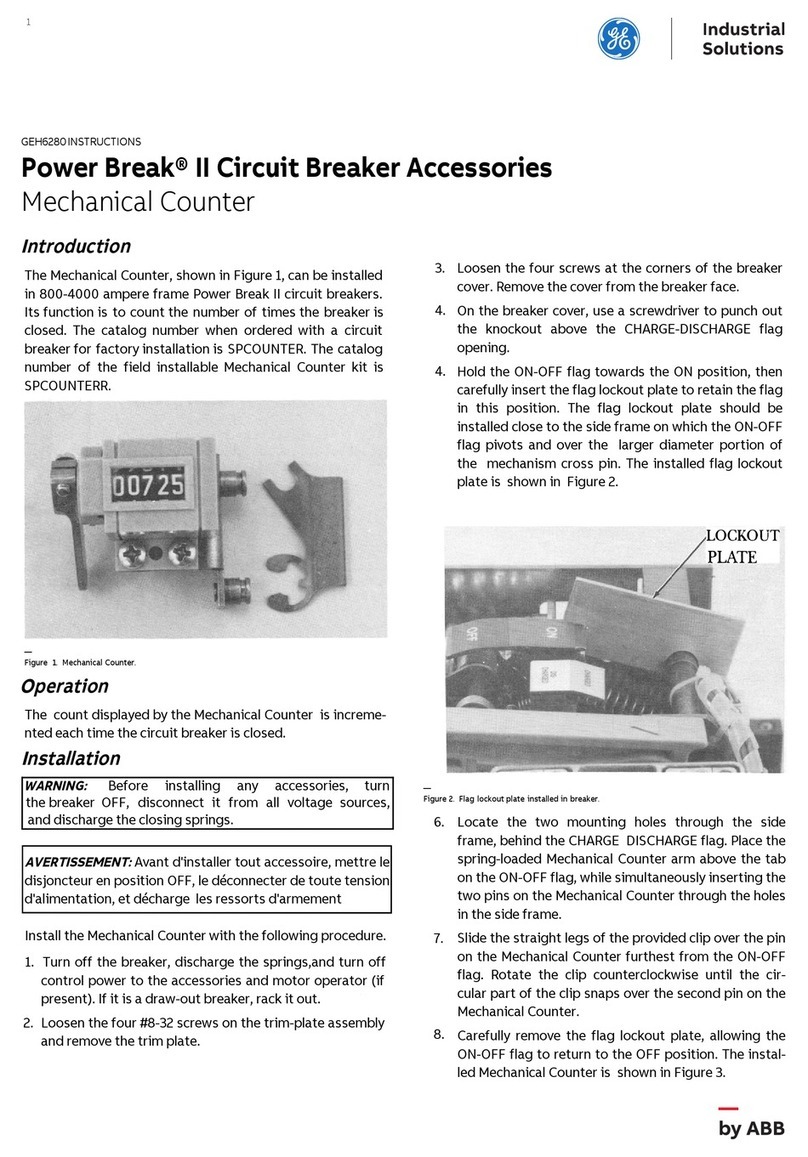
ABB SACE Emax 2 Manual

ABB

ABB SACE Emax 2 Manual

ABB SACE Emax 2 User manual

ABB

ABB SACE Emax 2 User manual

ABB SACE Emax 2 User manual

ABB

ABB SACE Emax 2 User manual

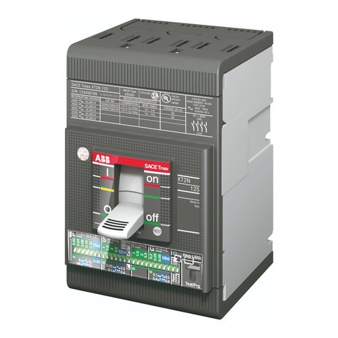
ABB SACE Tmax XT User manual

ABB

ABB SACE Tmax XT User manual

ABB VD4 Series Installation and operating instructions

ABB

ABB VD4 Series Installation and operating instructions

ABB AMVAC User manual

ABB

ABB AMVAC User manual

ABB VM1 User manual

ABB

ABB VM1 User manual

ABB T7-T7M-X1 User guide

ABB

ABB T7-T7M-X1 User guide

ABB TMAX MOE User manual

ABB

ABB TMAX MOE User manual

ABB SACE Emax 2 User manual

ABB

ABB SACE Emax 2 User manual

ABB VD4 36 Quick guide

ABB

ABB VD4 36 Quick guide

ABB SACE Tmax XT5 User manual

ABB

ABB SACE Tmax XT5 User manual

ABB 5VHK 250 Installation and operating instructions

ABB

ABB 5VHK 250 Installation and operating instructions

ABB Tmax MIR-V User manual

ABB

ABB Tmax MIR-V User manual

ABB HD4/R User manual

ABB

ABB HD4/R User manual

ABB SACE Emax E2.2 User guide

ABB

ABB SACE Emax E2.2 User guide

ABB SACE Emax 2 E2.2 User guide

ABB

ABB SACE Emax 2 E2.2 User guide

ABB SACE Emax 2 Product manual

ABB

ABB SACE Emax 2 Product manual

ABB ReliaMod RMS212522LRLR User manual

ABB

ABB ReliaMod RMS212522LRLR User manual

ABB SACE Emax Guide

ABB

ABB SACE Emax Guide

ABB Emax 2 Retrofill AKR-30-800A Product manual

ABB

ABB Emax 2 Retrofill AKR-30-800A Product manual

ABB SACE Emax 2 E2.2 User manual

ABB

ABB SACE Emax 2 E2.2 User manual

ABB SACE Tmax T6 User manual

ABB

ABB SACE Tmax T6 User manual

Popular Circuit Breaker manuals by other brands

CHINT NL1-63 User instruction

CHINT

CHINT NL1-63 User instruction

Eaton FAZ-XHIN11 installation instructions

Eaton

Eaton FAZ-XHIN11 installation instructions

Eaton NZM2-XSRM-LR Instruction leaflet

Eaton

Eaton NZM2-XSRM-LR Instruction leaflet

Camtec ESB303 quick start guide

Camtec

Camtec ESB303 quick start guide

Eaton EASY256-HCI Instruction leaflet

Eaton

Eaton EASY256-HCI Instruction leaflet

Siemens SDV-4A instruction manual

Siemens

Siemens SDV-4A instruction manual

GE FASHT Series quick start guide

GE

GE FASHT Series quick start guide

Eaton PKE65/AK/XTU-65-SP quick start guide

Eaton

Eaton PKE65/AK/XTU-65-SP quick start guide

Siemens 3VA9 3 0QF 0 Series operating instructions

Siemens

Siemens 3VA9 3 0QF 0 Series operating instructions

Eaton Power Defense PDG6 Instruction leaflet

Eaton

Eaton Power Defense PDG6 Instruction leaflet

hager HBB161H User instructions

hager

hager HBB161H User instructions

Eaton DST-2-VR+ Series Instruction book

Eaton

Eaton DST-2-VR+ Series Instruction book

Siemens MBKVA5262A Series installation instructions

Siemens

Siemens MBKVA5262A Series installation instructions

TERASAKI TemBreak PRO T2MS4 instruction manual

TERASAKI

TERASAKI TemBreak PRO T2MS4 instruction manual

OEZ ARION WL Instructions for use

OEZ

OEZ ARION WL Instructions for use

brennenstuhl BDI-S 30 V2 Directions for use

brennenstuhl

brennenstuhl BDI-S 30 V2 Directions for use

Allen-Bradley 194E installation instructions

Allen-Bradley

Allen-Bradley 194E installation instructions

Westinghouse DH-P Series instructions

Westinghouse

Westinghouse DH-P Series instructions

manuals.online logo
manuals.online logoBrands
  • About & Mission
  • Contact us
  • Privacy Policy
  • Terms and Conditions

Copyright 2025 Manuals.Online. All Rights Reserved.