6
A
B
3
4
2
1
5
3. Reveiving, handling, and storage
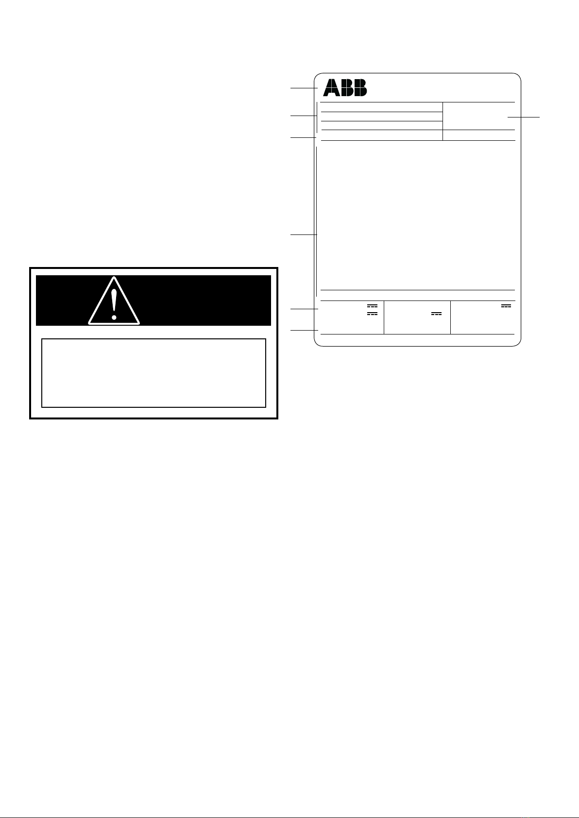
Fig. 1
Caption
A Circuit-breaker rating plate.
B Operating mechanism rating plate.
1 Type of apparatus.
2 Symbols of compliance with Standards.
3 Serial number.
4 Circuit-breaker characteristics.
5 Characteristics of the operating mechanism auxiliaries.
Vmax/W and Vmax circuit-breakers are subject to complete
factory production tests and inspection prior to packaging
and shipment. The shipping package is designed to provide
reasonable protection during shipment and to provide
convenient handling. Accessories such as opening handles
and racking handles are shipped separately from the circuit-
breaker.
The circuit-breaker is shipped in special packing, in the open
position.
Each piece of apparatus is protected by a plastic cover
to prevent any infiltration of water during the loading and
unloading stages and to keep the dust off during storage.
3.1. Receiving
Immediately upon receipt of the circuit-breaker(s), examine
the carton(s) to determine if any damage or loss was
sustained during transit. If damage or indication of rough
handling is evident, file a damage claim at once with the
carrier and promptly notify the nearest district office. ABB
is not responsible for damage to goods which occur after
delivery. However, ABB will lend assistance if notified of
claims. Use care in unpacking the circuit-breaker to avoid
damaging any circuit-breaker parts.
Unpack circuit-breakers as soon as possible after receipt.
If unpacking is delayed, difficulty may be experienced in
making a claim for damages not evident upon receipt.
Check the contents of each carton against the packing list
before discarding any packing material. If any discrepancy
is discovered, promptly notify the nearest district office.
Information specifying the purchase order number, carton
number, and part numbers of damaged or missing parts
should accompany the claim.
On receipt, check the state of the apparatus, integrity of the
packing and correspondence with the nameplate data (see
fig. 1) with what is specified in the order confirmation and in
the accompanying shipping notes.
Also make sure that all the materials described in the shipping
notes are included in the supply.
Should any damage or irregularity be noted in the supply
on unpacking, notify ABB (directly or through the agent or
supplier) as soon as possible and in any case within five days
of receipt.
The apparatus is only supplied with the accessories specified
at the time of ordering and validated in the order confirmation
sent by ABB.
The accompanying documents inserted in the shipping
packing are:
– instruction manual (this document)
– test certification
– identification label
– copy of the shipping documents
– electric wiring diagram.
Other documents which are sent prior to shipment of the
apparatus are:
– order confirmation
– original shipping advice notes
– any drawings or documents referring to special
configurations/conditions.
BEFORE CARRYING OUT ANY OPERATION,
ALWAYS MAKE SURE THAT THE SPRINGS
ARE DISCHARGED AND THAT THE
APPARATUS IS IN THE OPEN POSITION.
CAUTION
CIRCUIT-BREAKER ANSI C37.04
Vmax/W 15.12.31
SN 1VC1 BA 000000XX PR. YEAR 2010
M MASS 84 kg
Ur VOLTAGE 15 kV
Up LIGHTNING IMPULSE WITHSTAND VOLTAGE 95 kV
fr FREQUENCY 60 Hz
Ir NORMAL CURRENT 1200 A
Ik SHORT TIME WITHSTAND CURRENT 31.5 kA
tk DURATION OF SHORT CIRCUIT 2 s
Ise SHORT CIRCUIT BREAKING CURRENT 31.5 kA
MAKING CAPACITY (PEAK VALUE) 82 kA
AT THE VOLTAGE OF 15 kV
D.C. COMPONENT < = 44 %
RATED CLOSING TIME 45 ... 80 ms
RATED INTERRUPTING TIME < = 50 ms
OPERATING SEQUENCE O-0,3S-CO-3MI N-CO
INSTRUCTION MANUAL 1VCD600929
E. lECTRICAL DIAGRAM 1VCD400054 (E1010) \~ I
FIG.01 FIG.02 FIG.07 FIG.OS FIG.33 ~ ~\,
llllllllIIlllllllIlllllllIllllllllllllllllllIlIlllllllIlllllllIllllllllll
EL1 OPERATING MECHANISM
-MC 125 V -MS 125 V
-M01 125 V -RL2 125 V
Made by ABB, Italy