L0186
RH0025.002 2/22
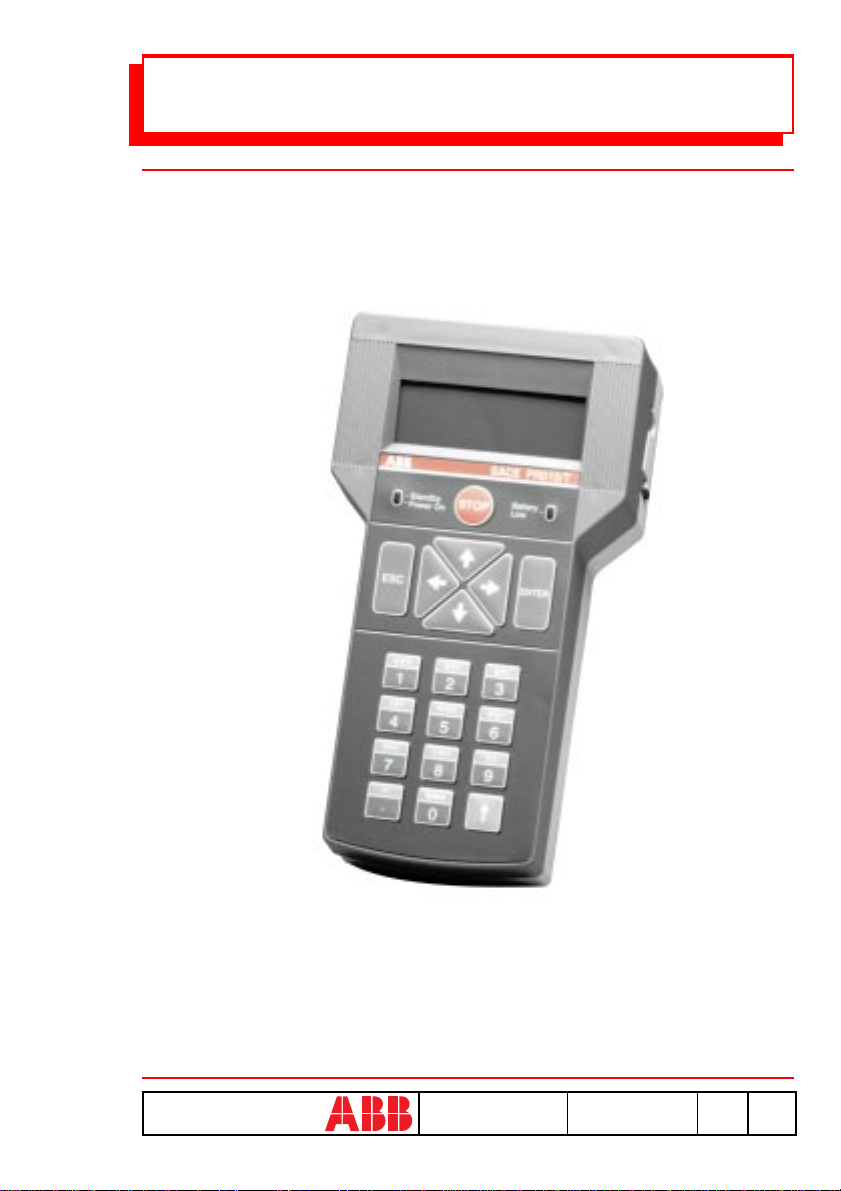
ABB SACE SACE PR010/T
Contents
1. SAFETY NOTES ....................................................................................... 3
2. DEFINITIONS AND ABBREVIATIONS ............................................... 4
3. GENERAL INFORMATION ................................................................... 4
3.1. INTRODUCTION ........................................................................................ 4
3.2. PUT IN SERVICE ....................................................................................... 5
3.3. GENERAL DESCRIPTION ............................................................................ 5
4. FUNCTIONS.............................................................................................. 6
4.1. TEST FUNCTIONS ..................................................................................... 6
4.1.1. Trip test ........................................................................................ 6
4.1.2. Protection functions test ............................................................. 6
4.1.3. Communication functions test..................................................... 7
4.2. PROGRAMMING FUNCTION ......................................................................... 7
4.3. PARAMETER READING FUNCTION ............................................................... 8
4.4. PROTECTION UNIT INTERFACE ................................................................... 8
4.5. PC INTERFACE ........................................................................................ 8
4.6. TEST REPORT .......................................................................................... 8
4.7. SPECIAL FUNCTIONS ............................................................................... 10
5. SOFTWARE............................................................................................. 11
5.1. DESCRIPTION ........................................................................................ 11
5.1.1. Report downloading .................................................................. 12
5.1.2. Test unit configuration .............................................................. 12
5.1.3. Software updating ..................................................................... 12
5.2. COMMUNICATION WITH PC .................................................................... 12
5.2.1. SW updating procedure ............................................................. 12
5.2.2. Test report downloading procedure .......................................... 14
5.2.3. Test report erasing ..................................................................... 15
5.3. Protection Unit Reference ......................................................... 15
6. TECHNICAL SPECIFICATIONS ........................................................ 16
6.1. USER INTERFACE ................................................................................... 16
6.2. POWER SUPPLY ...................................................................................... 16
6.3. INPUTS/OUTPUTS .................................................................................. 17
6.4. MECHANICAL SPECIFICATIONS ................................................................. 17
6.5. STANDARD EQUIPMENT .......................................................................... 18
6.6. APPLICABLE STANDARDS ........................................................................ 18
6.7. ERROR MESSAGES AND TROUBLESHOOTING TABLE ...................................... 19
6.8. NOTES ................................................................................................. 21