manuals.online logo
Brands
  1. Home
  2. •
  3. Brands
  4. •
  5. LOVATO ELECTRIC
  6. •
  7. Control Unit
  8. •
  9. LOVATO ELECTRIC EXP10 14 User manual

LOVATO ELECTRIC EXP10 14 User manual

p. 1 / 12
EXP10 14 EXP10 14
Модуль расширения Expansion module
интерфейс PROFIBUS® DP PROFIBUS® DP interface
ИНСТРУКЦИЯ ПО ЭКСПЛУАТУЦИИ INSTRUCTIONS MANUAL
● При проведение обслуживания устройства, отключите все напряжения
измерения и питания а такжже закоротите входы трансформаторов
Напряжениеа.
● Прибор может быть модифицирован производителем без предварительного
уведомления.
● Технические данные иописания представленные вданной инструкции
служат для пояснения ине дают гарантия от ошибок, случайностей и
непредвиденных обстоятельств.
● Очистка прибора производиться сухой мягкой тканью без использования
абразива иагрессивных жидкостей.
● Before any intervention, disconnect all the circuits.
●The manufacturer cannot be held responsible for electrical safety in case of
improper use of the equipment.
● Products illustrated herein are subject to alteration and changes without prior
notice. Technical data and descriptions in the documentation are accurate, to the
best of our knowledge, but no liabilities for errors, omissions or contingencies
arising therefrom are accepted.
● Clean the instrument with a soft dry cloth, do not use abrasives, liquid
detergents or solvents
Введение
Модули расширения серии EXP разработаны для увеличения функций
связи, I/O, памяти ианализа приборов измерения.
Модуль EXP10 1 снабжен изолированным серийным интерфейсом
PROFIBUS. Модуль может присоединяться к базовому прибору путем
установки в разъем. При подаче напряжения питания на систему, база
автоматически опознает модуль, настройка модуля EXP
производиться из меню базового прибора простым путем.
Introduction
The EXP units for Lovato plug in expandable products are designed and
developed to enhance the functions of connectivity, I/O, memory and
analysis of the instrument to which it is connected.
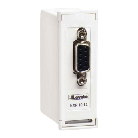
The EXP10 14 implements the isolated PROFIBUS® serial interface.
This module can be used in conjunction with a Lovato device with EXP
expansion bus. The module connection will be done simply by plug it in
to the expansion slot of the base instrument.. At the power on of the
system, the instrument will automatically recognize the units and the EXP
parameters setup will be done directly from the proper instrument menu
in an easy way.
Описание
Компактный размер (64mmx38mmx22mm)
Прямая установка на базовый прибор.
Изоляция 2kVrms при 1минуте от базы.
Интерфейс PROFIBUS® DP до 12М
ПроНапряжениеол TCP/IP.
Максимальное количество байтов: 18 ВХОДОВ 34 ВЫХОДОВ
Автоматическая скорость (9,600 - 19,200 - 45,450 - 93,750 -
187,500 -500,000 - 1.5M - 3M - 6M - 12M bps)
Стандартный 9 штырьковый разъем
Файл GSD доступен к скачиванию (www.lovatoelectric.com)
Description
Compact size (64mmx38mmx22mm).
Direct plug in on the base instrument.
2KVrms for 1 minute of insulation from the base module.
PROFIBUS® DP slave, up to 12M.
Maximum number of exchange bytes: 18 INPUT 34 OUTPUT.
Auto Baud-rate (9,600 - 19,200 - 45,450 - 93,750 - 187,500 -
500,000 - 1.5M - 3M - 6M - 12M bps)
Standard 9-pin D-sub female connector
File .GSD download available (www.lovatoelectric.com).
Совместимость продуктов Lovato
Модули расширения EXP10 14 может присоединяться кдругим
продуктам Lovato снабженными EXP разъемом. Проверьте
совместимость согласно следующей таблице:
Базовое устройство
Версия SW баз. устройства
DMG800
≥06
DMG900
≥04
Lovato product compatibility
EXP10 14 can be connected to a Lovato Electric product fitted by EXP
receptacle slot. Verify the compatibility with the following table:
Base device
Base device SW Rev.
DMG800
≥06
DMG900
≥04
I297 I RU 1010
ВНИМАНИЕ!!
●Внимательно прочтите инструкцию преред применением и
установкой .
●Данное оборудование должно устанавливаться
квалифицированным персоналом, согласно стандартам во
избежание несчастных случаев и аварий.
WARNING!
Carefully read the manual before the installation or use.
This equipment is to be installed by qualified personnel,
complying to current standards, to avoid damages or safety
hazards.
ВНИМАНИЕ!
●Когда модуль EXP установлен на прибор серии
DMG, обязательно установите опечатываемые крышки
разъмов, поставляемые смультиметром.
WARNING!
When the EXP... module is installed on a DMG series
multimeter, it is mandatory to install the sealable
terminal block covers supplied with the multimeter.
p. 2 / 12
Процедура присоединения модулей
Module connection procedure
1. Отключите напряжение.
2. Удалите крышки и блокировки разъемов.
3. Удалите заглушку разъема ирасположите модуль сразъемом
так, чтобы его можно было вставить в разъем.
4. Вставьте модуль EXP10 14 как показано на риунке.
5. Установите на место крышки иблокировки разъемов.
6. Подайте напряжение на систему (прибор автоматически опознает
модуль).
ПРИМЕЧАНИЕ: при извлечении модуля EXP (напряжение отключено
и вынуты все возможные блокировки и крышки разъемов, которые
могут препятствовать извлечению), нажмите на точку, обозначенную *
и выньте модуль.
1. Remove all dangerous voltage.
2. Remove the terminal covers and terminal block.
3. Remove the expansion slot cover of the Lovato product at the
position in which the EXP… module will be plugged in to.
4. Insert the EXP10 14 as illustrated in the above diagram.
5. Refit the terminal block and terminal cover.
6. Power up the system (the base product will automatically
recognise the expansion unit).
NOTE: Remove all dangerous voltage and repeat the operations from
step 5 to step 2 in inverse order. Press in the point indicated by the * in
the drawing in order to remove the module.
Программируемые параметры
Адреса PROFIBUS® (ведомые) устанавливаются базовым
устройством DMG параметром P.07.x.01.
Если пределы с1 по 125 установлены некорректно, на
дополнительной странице будет сообщение об ошибке.
Параметр P.07.x.08 должен использоваться только вслучае
когда на управляемом устройстве PROFIBUS® не возможна
установка байтовых номеров ВХОДА-ВЫХОДА. Возможные
величины параметров с 1001 по 1017 указаны в следующей
таблице:
ВЕЛИЧ.
КОНФИГ. ВЫХОД/ВХОД
1001
1 ВЫХОД 34 ВХОД
1002
4 ВЫХОД 6 ВХОД
1003
6 ВЫХОД 10 ВХОД
1004
8 ВЫХОД 14 ВХОД
1005
10 ВЫХОД 18 ВХОД
1006
12 ВЫХОД 22 ВХОД
1007
14 ВЫХОД 26 ВХОД
1008
16 ВЫХОД 30 ВХОД
1009
18 ВЫХОД 34 ВХОД
1010
2 ВЫХОД
1011
3 ВЫХОД
1012
4 ВЫХОД
1013
5 ВЫХОД
1014
6 ВЫХОД
1015
7 ВЫХОД
1016
8 ВЫХОД
1017
9 ВЫХОД
Parameter programming
The PROFIBUS® slave node address is set in the DMG base
device with parameter P.07.x.01.
The range is from 1 to 125; in case of incorrect setting, the error
situation will be shown on the expansion status page.
The P.07.x.08 parameter must be used only in cases where the
PROFIBUS® master device is not able to set INPUT-OUTPUT byte
number. Valid values for this parameter range from 1001 to 1017,
with the following meaning:
VALUE
OUTPUT/INPUT CONFIG.
1001
1 OUTPUT 34 INPUT
1002
4 OUTPUT 6 INPUT
1003
6 OUTPUT 10 INPUT
1004
8 OUTPUT 14 INPUT
1005
10 OUTPUT 18 INPUT
1006
12 OUTPUT 22 INPUT
1007
14 OUTPUT 26 INPUT
1008
16 OUTPUT 30 INPUT
1009
18 OUTPUT 34 INPUT
1010
2 OUTPUT
1011
3 OUTPUT
1012
4 OUTPUT
1013
5 OUTPUT
1014
6 OUTPUT
1015
7 OUTPUT
1016
8 OUTPUT
1017
9 OUTPUT
Функция шлюза (параметр P.07.x.09) не может быть
использована смодулем, поставьте этот параметр в OFF.
The gateway function (parameter P.07.x.09) cannot be used with
PROFIBUS® modules. Leave this parameter set to OFF.
CLICK!
1
2
3
*
Slot Slot Slot Slot
1 2 3 4
p. 3 / 12
ИСПОЛЬЗОВАНИЕ МОДУЛЯ EXP1014 СМУЛЬТИМЕТРАМИ СЕРИИ
DMG
USE OF EXP1014 WITH DMG SERIES MULTIMETERS
Чтение измерений
Читаемые измерения DMG сгруппированы в следующей таблице
(группы).
Для чтения группы измерений, необходимо установить
управляющее устройство вследующее конфигурации:
oВЫХОД = 1
oВХОД = 34
Либо выберите в файле LovatoXX.gsd модуль 19:
oМодуль = Измерение 34 IN / 1 OUT
Первый выходной байт выбирает группу измерений.
Первый байт входа согласуется стем же байтом выхода (для
определения доставленной таблицы измерений), второй байт не
используется, 32 последующих байта указывают читаемую
величину используя 4 байта каждый.
Следующая таблица показывает группы измерений.
Measurement reading
The measurements that can be read from the DMG are grouped in
several tables (groups).
To read a group of measurements, it is necessary to set the master
device with the following configuration:
oOUTPUT = 1
oINPUT = 34
Otherwise, select from LovatoXX.gsd module #19.
oModule = Measurement 34 IN / 1 OUT
The first output byte selects the measurement group.
The first byte of inputs reports the same byte as the output (to
indicate what measurement table is provided), the second byte is
not used, the 32 successive bytes contain the value of the
readings, using 4 bytes each.
The following tables lists the measurement groups:
ГРУППЫ ИЗМЕРЕНИЙ 0
MEASUREMENT GROUP 0
POS БАЙТ
БАЗА/UNIT
Группа измерений
Measurement group
1
Не используется
Not used
2
Фазн. напряж. L1 Мгновенн.
Instantaneous L1 Phase Voltage
3 - 6
V/100
Фазн. напряж. L2 Мгновенн.
Instantaneous L2 Phase Voltage
7 - 10
V/100
Фазн. напряж. L3 Мгновенн.
Instantaneous L3 Phase Voltage
11 - 14
V/100
Напряжение L1-L2 Мгновенн.
Instantaneous L1-L2 Voltage
15 - 18
V/100
Напряжение L3-L3 Мгновенн.
Instantaneous L2-L3 Voltage
19 - 22
V/100
Напряжение L3-L1 Мгновенн.
Instantaneous L3-L1 Voltage
23 - 26
V/100
Фазн. напряж. L4 Мгновенн. (DMG900)
Instantaneous L4 Phase Voltage (DMG900)
27 - 30
V/100
Частота Мгновенн.
Instantaneous Frequency
31 - 34
HZ/1000
ГРУППЫ ИЗМЕРЕНИЙ 1
MEASUREMENT GROUP 1
POS БАЙТ
БАЗА/UNIT
Группа измерений
Measurement group
1
Не используется
Not used
2
Фазный токL1 Мгновенн.
Instantaneous L1 Current
3 - 6
A/10000
Фазный токL2 Мгновенн.
Instantaneous L2 Current
7 - 10
A/10000
Фазный токL3 Мгновенн.
Instantaneous L3 Current
11 - 14
A/10000
Активная мощность L1 Мгновенн.
Instantaneous L1 Active Power
15 - 18
W/100
Активная мощность L2 Мгновенн.
Instantaneous L2 Active Power
19 - 22
W/100
Активная мощность L3 Мгновенн.
Instantaneous L3 Active Power
23 - 26
W/100
Фазный токN Мгновенн. (DMG900)
Instantaneous N Current(DMG900)
27 - 30
A/10000
Частота Мгновенн.
Instantaneous Frequency
31 - 34
HZ/1000
ГРУППЫ ИЗМЕРЕНИЙ 2
MEASUREMENT GROUP 2
POS БАЙТ
БАЗА/UNIT
Группа измерений
Measurement group
1
Не используется
Not used
2
Реактивная мощность L1 Мгновенн.
Instantaneous L1 Reactive Power
3 - 6
Var/100
Реактивная мощность L2 Мгновенн.
Instantaneous L2 Reactive Power
7 - 10
Var/100
Реактивная мощность L3 Мгновенн.
Instantaneous L3 Reactive Power
11 - 14
Var/100
Видимая мощностьL1 Мгновенн.
Instantaneous L1 Apparent Power
15 - 18
VA/100
Видимая мощностьL2 Мгновенн.
Instantaneous L2 Apparent Power
19 - 22
VA/100
Видимая мощностьL3 Мгновенн.
Instantaneous L3 Apparent Power
23 - 26
VA/100
Не используется
Not used
27 - 30
Не используется
Not used
31 - 34
p. 4 / 12
ГРУППЫ ИЗМЕРЕНИЙ 3
MEASUREMENT GROUP 3
POS БАЙТ
БАЗА/UNIT
Группа измерений
Measurement group
1
Не используется
Not used
2
Коэфф. мощностиL1 Мгновенн.
Instantaneous L1 Power Factor
3 - 6
/10000
Коэфф. мощностиL2 Мгновенн.
Instantaneous L2 Power Factor
7 - 10
/10000
Коэфф. мощностиL3 Мгновенн.
Instantaneous L3 Power Factor
11 - 14
/10000
CosPhi L1 Мгновенн.
Instantaneous L1 CosPhi
15 - 18
/10000
CosPhi L2 Мгновенн.
Instantaneous L2 CosPhi
19 - 22
/10000
CosPhi L3 Мгновенн.
Instantaneous L3 CosPhi
23 - 26
/10000
Частота Мгновенн.
Instantaneous Frequency
27 - 30
HZ/1000
Не используется
Not used
31 - 34
ГРУППЫ ИЗМЕРЕНИЙ 4
MEASUREMENT GROUP 4
POS БАЙТ
БАЗА/UNIT
Группа измерений
Measurement group
1
Не используется
Not used
2
Фазн. напряж. эквивал. Мгновенн.
Instantaneous Equivalent Phase Voltage
3 - 6
V/100
Напряжение concatenata эквивал.
Мгновенн.
Instantaneous Equivalent Phase-To-Phase Voltage
7 - 10
V/100
Ток эквивал. Мгновенн.
Instantaneous Equivalent Current
11 - 14
A/10000
Активная мощность эквивал. Мгновенн.
Instantaneous Equivalent Active Power
15 - 18
W/100
Реактивная мощность эквивал. Мгновенн.
Instantaneous Equivalent Reactive Power
19 - 22
var/100
Видимая мощностьэквивал. Мгновенн.
Instantaneous Equivalent Apparent Power
23 - 26
VA/100
Коэфф. мощностиэквивал. Мгновенн.
Instantaneous Equivalent Power Factor
27 - 30
/10000
Не используется
Not used
31 - 34
ГРУППЫ ИЗМЕРЕНИЙ 5
MEASUREMENT GROUP 5
POS BYTE
БАЗА/UNIT
Группа измерений
Measurement group
1
Не используется
Not used
2
АссиметрияНапряжение Фаза-
ФазаМгновенн.
Phase-Phase Voltage Asymmetry Instantaneous
3 - 6
%/100
АссиметрияНапряжение Фаза Ноль
Мгновенн.
Phase-Neural Voltage Asymmetry Instantaneous
7 - 10
%/100
АссиметрияТок Мгновенн.
Current Asymmetry Instantaneous
11- 14
%/100
Не используется
Not used
15- 18
Не используется
Not used
19- 22
Не используется
Not used
23- 26
Не используется
Not used
27- 30
Не используется
Not used
31- 34
ГРУППЫ ИЗМЕРЕНИЙ 6
MEASUREMENT GROUP 6
POS BYTE
БАЗА/UNIT
Группа измерений
Measurement group
1
Не используется
Not used
2
Thd Напряжение L1 Мгновенн.
Instantaneous L1 Voltage Thd
3 - 6
%/100
Thd Напряжение L2 Мгновенн.
Instantaneous L2 Voltage Thd
7 - 10
%/100
Thd Напряжение L3 Мгновенн.
Instantaneous L3 Voltage Thd
11- 14
%/100
Thd Напряжение I1 Мгновенн.
Instantaneous L1 Current Thd
15- 18
%/100
Thd Напряжение I2 Мгновенн.
Instantaneous L2 Current Thd
19- 22
%/100
Thd Напряжение I3 Мгновенн.
Instantaneous L3 Current Thd
23- 26
%/100
Thd Напряжение N-Земля Мгновенн.
Instantaneous N-Earth Voltage Thd
27- 30
%/100
Thd Ток N Мгновенн.
Instantaneous N Current Thd
31- 34
%/100
ГРУППЫ ИЗМЕРЕНИЙ 7
MEASUREMENT GROUP 7
POS BYTE
БАЗА/UNIT
Группа измерений
Measurement group
1
Не используется
Not used
2
Thd Напряжение L1-2 Мгновенн.
Instantaneous L1-2 Voltage Thd
3 - 6
%/100
Thd Напряжение L2-3 Мгновенн.
Instantaneous L2-3 Voltage Thd
7 - 10
%/100
Thd Напряжение L3-1 Мгновенн.
Instantaneous L3-1 Voltage Thd
11- 14
%/100
Не используется
Not used
15- 18
Не используется
Not used
19- 22
Не используется
Not used
23- 26
Не используется
Not used
27- 30
Не используется
Not used
31- 34
p. 5 / 12
ПРИМЕЧАНИЕ:
Группы с0 по 7 содержат последние полученные измерения без
фильтрации/усреднения.
Группы с10 по 17 содержат те же измерения, но эти величины
фильтрованы ипредставлены как мгновенные (IN) величины ,
показанные на экране.
Группы с20 по 27 содержат те же измерения, но максимальные
(HI) значения.
Группы с30 по 37 содержат те же измерения, но минимальные
(LO) значения.
Группы с40 по 47 содержат те же измерения, но средние (AV)
значения.
Группы с50 по 57 содержат те же измерения, но максимально
возможные (MD) значения.
NOTE:
Groups from 0 to 7 hold the last acquisition readings, without any
filtering/average.
Groups from 10 to 17 hold the same measurements, but their value is
filtered and corresponds to the instantaneous (IN) value shown on
display.
Groups from 20 to 27 hold the same measurements, but their value is
the maximum (HI).
Groups from 30 to 37 hold the same measurements, but their value is
the minimum (LO).
Groups from 40 to 47 hold the same measurements, but their value is
the average (AV).
Groups from 50 to 57 hold the same measurements, but their value is
the max demand (MD).
ПРИМЕЧАНИЕ:
Группы с100 по 104 содержат последние полученные измерения
без фильтрации/усреднения.
Группы с105 по 109 содержат те же измерения, но эти величины
фильтрованы ипредставлены как мгновенные (IN) величины,
показанные на экране.
Группы с100 по 114 содержат те же измерения, но максимальные
(HI) значения.
Группы с115 по 119 содержат те же измерения, но минимальные
(LO) значения.
Группы с120 по 124 содержат те же измерения, но средние (AV)
значения.
Группы с125 по 129 содержат те же измерения, но максимально
возможные (MD) значени
NOTE:
Groups from 100 to 104 hold the last acquisition readings, without any
filtering/average.
Groups from 105 to 109 hold the same measurements, but their value
is filtered and corresponds to instantaneous (IN) value shown on
display.
Groups from 110 to 114 hold the same measurements, but their value
is the maximum (HI).
Groups from 115 to 119 hold the same measurements, but their value
is the minimum (LO).
Groups from 120 to 124 hold the same measurements, but their value
is the average (AV).
Groups from 125 to 129 hold the same measurements, but their value is
the max demand (MD).
ГРУППЫ ИЗМЕРЕНИЙ 100
MEASUREMENT GROUP 100
POS BYTE
БАЗА/UNIT
Группа измерений
Measurement group
1
Не используется
Not used
2
Фазн. напряж. L1 Мгновенн.
Instantaneous L1 Phase Voltage
3 - 6
V/100
Фазн. напряж. L2 Мгновенн.
Instantaneous L2 Phase Voltage
7 - 10
V/100
Фазн. напряж. L3 Мгновенн.
Instantaneous L3 Phase Voltage
11- 14
V/100
Фазный токL1 Мгновенн.
Instantaneous L1 Current
15- 18
A/10000
Фазный токL2 Мгновенн.
Instantaneous L2 Current
19- 22
A/10000
Фазный токL3 Мгновенн.
Instantaneous L3 Current
23- 26
A/10000
Частота Мгновенн.
Instantaneous Frequency
27- 30
Hz/1000
Не используется
Not used
31- 34
ГРУППЫ ИЗМЕРЕНИЙ 101
MEASUREMENT GROUP 101
POS BYTE
БАЗА/UNIT
Группа измерений
Measurement group
1
Не используется
Not used
2
Напряжение L1-L2 Мгновенн.
Instantaneous L1-L2 Voltage
3 - 6
V/100
Напряжение L3-L3 Мгновенн.
Instantaneous L2-L3 Voltage
7 - 10
V/100
Напряжение L3-L1 Мгновенн.
Instantaneous L3-L1 Voltage
11 - 14
V/100
Фазный токL1 Мгновенн.
Instantaneous L1 Current
15 - 18
A/10000
Фазный токL2 Мгновенн.
Instantaneous L2 Current
19 - 22
A/10000
Фазный токL3 Мгновенн.
Instantaneous L3 Current
23 - 26
A/10000
Частота Мгновенн.
Instantaneous Frequency
27 - 30
Hz/1000
Не используется
Not used
31 - 34
ГРУППЫ ИЗМЕРЕНИЙ 102
MEASUREMENT GROUP 102
POS BYTE
БАЗА/UNIT
Группа измерений
Measurement group
1
Не используется
Not used
2
Фазн. напряж. L1 Мгновенн.
Instantaneous L1 Phase Voltage
3 - 6
V/100
Фазный токL1 Мгновенн.
Instantaneous L1 Current
7 - 10
A/10000
Активная мощность L1 Мгновенн.
Instantaneous L1 Active Power
11 - 14
W/100
Реактивная мощность L1 Мгновенн.
Instantaneous L1 Reactive Power
15 - 18
Var/100
Видимая мощностьL1 Мгновенн.
Instantaneous L1 Apparent Power
19 - 22
VA/100
Коэфф. мощностиL1 Мгновенн.
Instantaneous L1 Power Factor
23 - 26
/10000
CosPhi L1 Мгновенн.
Instantaneous L1 CosPhi
27 - 30
/10000
Частота Мгновенн.
Instantaneous Frequency
31 - 34
Hz/1000
p. 6 / 12
ГРУППЫ ИЗМЕРЕНИЙ 130
MEASUREMENT GROUP 130
POS BYTE
БАЗА/UNIT
Группа измерений
Measurement group
1
Не используется
Not used
2
2. Гармоника Напряжение L1
L1 Voltage 2°Harmonic
3 - 4
%
3. Гармоника Напряжение L1
L1 Voltage 3° Harmonic
5 - 6
%
4. Гармоника Напряжение L1
L1 Voltage 4° Harmonic
7 - 8
%
5. Гармоника Напряжение L1
L1 Voltage 5° Harmonic
9 - 10
%
6. Гармоника Напряжение L1
L1 Voltage 6° Harmonic
11 - 12
%
7. Гармоника Напряжение L1
L1 Voltage 7°Harmonic
13 - 14
%
8. Гармоника Напряжение L1
L1 Voltage 8° Harmonic
15 - 16
%
9. Гармоника Напряжение L1
L1 Voltage 9° Harmonic
17 - 18
%
10. Гармоника Напряжение L1
L1 Voltage 10°Harmonic
19 - 20
%
11 Гармоника Напряжение L1
L1 Voltage 11°Harmonic
21 - 22
%
12. Гармоника Напряжение L1
L1 Voltage 12° Harmonic
23 - 24
%
13. Гармоника Напряжение L1
L1 Voltage 13°Harmonic
25 - 26
%
14. Гармоника Напряжение L1
L1 Voltage 14° Harmonic
27 - 28
%
15. Гармоника Напряжение L1
L1 Voltage 15° Harmonic
29 - 30
%
16. Гармоника Напряжение L1
L1 Voltage 16°Harmonic
31 - 32
%
17. Гармоника Напряжение L1
L1 Voltage 17°Harmonic
33 - 34
%
ГРУППЫ ИЗМЕРЕНИЙ 131
MEASUREMENT GROUP 131
POS BYTE
БАЗА/UNIT
Группа измерений
Measurement group
1
Не используется
Not used
2
18. Гармоника Напряжение L1
L1 Voltage 18° Harmonic
3 - 4
%
19. Гармоника Напряжение L1
L1 Voltage 19° Harmonic
5 - 6
%
20. Гармоника Напряжение L1
L1 Voltage 20° Harmonic
7 - 8
%
21. Гармоника Напряжение L1
L1 Voltage 21° Harmonic
9 - 10
%
22. Гармоника Напряжение L1
L1 Voltage 22°Harmonic
11 - 12
%
23. Гармоника Напряжение L1
L1 Voltage 23° Harmonic
13 - 14
%
24. Гармоника Напряжение L1
L1 Voltage 24°Harmonic
15 - 16
%
25 Гармоника Напряжение L1
L1 Voltage 25° Harmonic
17 - 18
%
26. Гармоника Напряжение L1
L1 Voltage 26°Harmonic
19 - 20
%
27. Гармоника Напряжение L1
L1 Voltage 27° Harmonic
21 - 22
%
28. Гармоника Напряжение L1
L1 Voltage 28° Harmonic
23 - 24
%
29. Гармоника Напряжение L1
L1 Voltage 29°Harmonic
25 - 26
%
30. Гармоника Напряжение L1
L1 Voltage 30°Harmonic
27 - 28
%
31. Гармоника Напряжение L1
L1 Voltage 31°Harmonic
29 - 30
%
32. Гармоника Напряжение L1
L1 Voltage 32°Harmonic
31 - 32
%
33. Гармоника Напряжение L1
L1 Voltage 33°Harmonic
33 - 34
%
ГРУППЫ ИЗМЕРЕНИЙ 132 (DMG900)
MEASUREMENT GROUP 132 (DMG900 only)
POS BYTE
БАЗА/UNIT
Группа измерений
Measurement group
1
Не используется
Not used
2
34 Гармоника Напряжение L1
L1 Voltage 34° Harmonic
3 - 4
%
35. Гармоника Напряжение L1
L1 Voltage 35°Harmonic
5 - 6
%
36. Гармоника Напряжение L1
L1 Voltage 36°Harmonic
7 - 8
%
37. Гармоника Напряжение L1
L1 Voltage 37°Harmonic
9 - 10
%
38. Гармоника Напряжение L1
L1 Voltage 38° Harmonic
11 - 12
%
39 Гармоника Напряжение L1
L1 Voltage 39° Harmonic
13 - 14
%
40. Гармоника Напряжение L1
L1 Voltage 40°Harmonic
15 - 16
%
41. Гармоника Напряжение L1
L1 Voltage 41° Harmonic
17 - 18
%
42. Гармоника Напряжение L1
L1 Voltage 42° Harmonic
19 - 20
%
43. Гармоника Напряжение L1
L1 Voltage 43°Harmonic
21 - 22
%
44 Гармоника Напряжение L1
L1 Voltage 44°Harmonic
23 - 24
%
45. Гармоника Напряжение L1
L1 Voltage 45° Harmonic
25 - 26
%
46. Гармоника Напряжение L1
L1 Voltage 46°Harmonic
27 - 28
%
47. Гармоника Напряжение L1
L1 Voltage 47° Harmonic
29 - 30
%
48. Гармоника Напряжение L1
L1 Voltage 48°Harmonic
31 - 32
%
49 Гармоника Напряжение L1
L1 Voltage 49°Harmonic
33 - 34
%
p. 7 / 12
Группа измерений с 135 по 139 содержат те же данные что группы
с130 a 134 но относяться к Фазн. напряж. L2
Группа измерений с 140 по 144 содержат те же данные что группы
с130 a 134 но относяться к Фазн. напряж. L3
Группа измерений с 145 по 149 содержат те же данные что группы
с130 a 134 но относяться к Фазный току L1
Группа измерений с 150 по 154 содержат те же данные что группы
с130 a 134 но относяться к Фазный току L2
Группа измерений с 155 по 159 содержат те же данные что группы
130 a 134 но относяться к Фазный току L3
Группа измерений с 160 по 164 содержат те же данные что группы
с130 a 134 но относяться к Напряжению L1- L2
Группа измерений с 165 по 169 содержат те же данные что группы
с130 a 134 но относяться к Напряжению L2- L3
Группа измерений с 170 по 174 содержат те же данные что группы
с130 a 134 но относяться к Напряжению L3- L1
Группа измерений с 175 по 179 содержат те же данные что группы
с130 a 134 но относяться к Напряжению N-Земля
Группа измерений с 180 по 184 содержат те же данные что группы
с130 a 134 но относяться к Ток нейтрали.
The measurement group from 135 to 139 hold same data as groups
130 to 134 but are referred to L2 phase voltage.
The measurement group from 140 to 144 hold same data as groups
130 to 134 but are referred to L3 phase voltage.
The measurement group from 145 to 149 hold same data as groups
130 to 134 but are referred to L1 phase current.
The measurement group from 150 to 154 hold same data as groups
130 to 134 but are referred to L2 phase current.
The measurement group from 155 to 159 hold same data as groups
130 to 134 but are referred to L3 phase current.
The measurement group from 160 to 164 hold same data as groups
130 to 134 but are referred to L1-L2 voltage.
The measurement group from 165 to 169 hold same data as groups
130 to 134 but are referred to L2-L3 voltage.
The measurement group from 170 to 174 hold same data as groups
130 to 134 but are referred to L3-L1 voltage
The measurement group from 175 to 179 hold same data as groups
130 to 134 but are referred to Neutral-Earth voltage.
The measurement group from 180 to 184 hold same data as groups
130 to 134 but are referred to Neutral current.
ГРУППЫ ИЗМЕРЕНИЙ 133 (только для
DMG900)
MEASUREMENT GROUP 133 (DMG900 only)
POS BYTE
БАЗА/UNIT
Группа измерений
Measurement group
1
Не используется
Not used
2
50. Гармоника Напряжение L1
L1 Voltage 50° Harmonic
3 - 4
%
51. Гармоника Напряжение L1
L1 Voltage 51°Harmonic
5 - 6
%
52. Гармоника Напряжение L1
L1 Voltage 52°Harmonic
7 - 8
%
53 Гармоника Напряжение L1
L1 Voltage 53° Harmonic
9 - 10
%
54. Гармоника Напряжение L1
L1 Voltage 54° Harmonic
11 - 12
%
55. Гармоника Напряжение L1
L1 Voltage 55°Harmonic
13 - 14
%
56. Гармоника Напряжение L1
L1 Voltage 56°Harmonic
15 - 16
%
57. Гармоника Напряжение L1
L1 Voltage 57°Harmonic
17 - 18
%
58. Гармоника Напряжение L1
L1 Voltage 58°Harmonic
19 - 20
%
59. Гармоника Напряжение L1
L1 Voltage 59°Harmonic
21 - 22
%
60. Гармоника Напряжение L1
L1 Voltage 60°Harmonic
23 - 24
%
61 Гармоника Напряжение L1
L1 Voltage 61°Harmonic
25 - 26
%
62. Гармоника Напряжение L1
L1 Voltage 62°Harmonic
27 - 28
%
63. Гармоника Напряжение L1
L1 Voltage 63°Harmonic
29 - 30
%
Не используется
Not used
31 - 32
%
Не используется
Not used
33 - 34
%
p. 8 / 12
Группа измерений с 190 по 191 содержат те же данные что группы с
188 a 189 но относятся кТариф B
Группа измерений с 192 по 193 содержат те же данные что группы с
188 a 189 но относятся кТариф C
Группа измерений с 194 по 195 содержат те же данные что группы с
188 a 189 но относятся кТариф D
Группа измерений с 196 по 197 содержат те же данные что группы с
188 a 189 но относятся кТариф E
Группа измерений с 198 по 199 содержат те же данные что группы с
188 a 189 но относятся кТариф F
Группа измерений с 200 по 201 содержат те же данные что группы с
188 a 189 но относятся кТариф G
Группа измерений с 202 по 203 содержат те же данные что группы с
188 a 189 но относятся кТариф H
The measurement groups from 190 to 191 hold same data as 188 to
189, referred to tariff B.
The measurement groups from 192 to 193 hold same data as 188 to
189, referred to tariff C.
The measurement groups from 194 to 195 hold same data as 188 to
189, referred to tariff D.
The measurement groups from 196 to 197 hold same data as 188 to
189, referred to tariff E.
The measurement groups from 198 to 199 hold same data as 188 to
189, referred to tariff F.
The measurement groups from 200 to 201 hold same data as 188 to
189, referred to tariff G.
The measurement groups from 202 to 203 hold same data as 188 to
189, referred to tariff 8H
ГРУППЫ ИЗМЕРЕНИЙ 186
MEASUREMENT GROUP 186
POS BYTE
БАЗА/UNIT
Группа измерений
Measurement group
1
Не используется
Not used
2
Мощность Активная Импортируемая общая
Total imported Active Energy
3 - 6
kwh/100
Мощность Активная Получаемая общая
Total exported Active Energy
7 - 10
kwh/100
Мощность Реактивная Импортируемая
общая
Total imported Reactive Energy
11 - 14
kvarh/100
Мощность Реактивная Получаемая общая
Total exported Reactive Energy
15 - 18
kvarh/100
Мощность видимая общая
Total Apparent Energy
19 - 22
kVAh/100
Мощность Активная Импортируемая
частичная
Partial imported Active Energy
23 - 26
kwh/100
Мощность Активная Получаемая частичная
Partial exported Active Energy
27 - 30
kwh/100
Не используется
Not used
31 - 34
ГРУППЫ ИЗМЕРЕНИЙ 187
MEASUREMENT GROUP 187
POS BYTE
%/
Группа измерений
Measurement group
1
Не используется
Not used
2
Мощность Реактивная Импортируемая
частичная
Partial imported Reactive Energy
3 - 6
kvarh/100
Мощность Реактивная Получаемая
частичная
Partial exported Reactive Energy
7 - 10
kvarh/100
Мощность видимая частичная
Partial Apparent Energy
11 - 14
kVAh/100
Не используется
Not used
15 - 18
Не используется
Not used
19 - 22
Не используется
Not used
23 - 26
Не используется
Not used
27 - 30
Не используется
Not used
31 - 34
ГРУППЫ ИЗМЕРЕНИЙ 188
MEASUREMENT GROUP 188
POS BYTE
БАЗА/UNIT
Группа измерений
Measurement group
1
Не используется
Not used
2
Тариф A Мощность Активная
Импортируемая
Active Energy Imported Tariff A
3 - 10
kwh/100
Тариф A Мощность Активная Получаемая
Active Energy Exported Tariff A
11 - 18
kwh/100
Тариф A Мощность Активная
Импортируемая
Reactive Energy Imported Tariff A
19 - 26
kvarh/100
Тариф A Мощность Активная Получаемая
Reactive Energy Exported Tariff A
27 - 34
kvarh/100
ГРУППЫ ИЗМЕРЕНИЙ 189
MEASUREMENT GROUP 189
POS BYTE
%/
Группа измерений
Measurement group
1
Не используется
Not used
2
Тариф A Мощность Видимая
Apparent Energy Tariff A
3 - 10
kVAh/100
Не используется
Not used
11 - 14
Не используется
Not used
15 - 18
Не используется
Not used
19 - 22
Не используется
Not used
23 - 26
Не используется
Not used
27 - 30
Не используется
Not used
31 - 34
p. 9 / 12
ГРУППЫ ИЗМЕРЕНИЙ 204
MEASUREMENT GROUP 204
POS BYTE
БАЗА/UNIT
Группа измерений
Measurement group
1
Не используется
Not used
2
Аналоговый вход 1
Analog Input 1
3 - 6
/100
Аналоговый вход 2
Analog Input 2
7 - 10
/100
Аналоговый вход 3
Analog Input 3
11 - 14
/100
Аналоговый вход 4
Analog Input 4
15 - 18
/100
Аналоговый вход 5
Analog Input 5
19 - 22
/100
Аналоговый вход 6
Analog Input 6
23 - 26
/100
Аналоговый вход 7
Analog Input 7
27 - 30
/100
Аналоговый вход 8
Analog Input 8
31 - 34
/100
ГРУППЫ ИЗМЕРЕНИЙ 205
MEASUREMENT GROUP 205
POS BYTE
БАЗА/UNIT
Группа измерений
Measurement group
1
Не используется
Not used
2
Аналоговый выход1
Analog Output 1
3 - 6
/1000
Аналоговый выход2
Analog Output 2
7 - 10
/1000
Аналоговый выход3
Analog Output 3
11- 14
/1000
Аналоговый выход4
Analog Output 4
15- 18
/1000
Аналоговый выход5
Analog Output 5
19- 22
/1000
Аналоговый выход6
Analog Output 6
23- 26
/1000
Аналоговый выход7
Analog Output 7
27- 30
/1000
Аналоговый выход8
Analog Output 8
31- 34
/1000
ГРУППЫ ИЗМЕРЕНИЙ 206
MEASUREMENT GROUP 206
POS BYTE
БАЗА/UNIT
Группа измерений
Measurement group
1
Не используется
Not used
2
Счетчик 1
Counter 1
3 - 6
No.
Счетчик 2
Counter 2
7 - 10
No.
Счетчик 3
Counter 3
11 - 14
No.
Счетчик 4
Counter 4
15 - 18
No.
Не используется
Not used
19 - 22
Не используется
Not used
23 - 26
Не используется
Not used
27 - 30
Не используется
Not used
31 - 34
ГРУППЫ ИЗМЕРЕНИЙ 207
MEASUREMENT GROUP 207
POS BYTE
БАЗА/UNIT
Группа измерений
Measurement group
1
Не используется
Not used
2
OR всех входов
OR of all Inputs
3 - 6
bool
OR всех выходов
OR of all Outputs
7 - 10
bool
OR всех сигналов
OR of all Alarms
11- 14
bool
OR всех Булевых логик
OR of all Boolean
15- 18
bool
OR всех пределов
OR All Limits
19- 22
bool
Не используется
Not used
23- 26
Не используется
Not used
27- 30
Не используется
Not used
31- 34
p. 10 / 12
Внешние переменные (группа 250)
Позаоляет изменять состояние внешних переменных (REMx)
командами PROFIBUS®.
Вэтом лучае пользователь должен установит номер выходного
байта используя формулу:
oOUTPUT (байты) = Nr. Удаленных переменных + 2
Либо выбрать вфайле LovatoXX.gsd один модуль с 28 по 35:
oModule = Set X variable
Где индикатор X –номер внешней переменной.
Пользовательское устройство устанавливает величину первого
байта 250 иследующие байты будут сшестнадцатиричной
величиной 0xAA если необходимо устанвить удаленные
переменные или величина 0xBB переменной должна быть
очищена. Другие величины останутся неизменными.
Пример:
Байт 1 0xFA (250) команда внешних переменных
Байт 2 0xAA (170) установ. внеш. переменные1
Байт 3 0xBB (187) внеш. переменные 2 очищены
Байт 4 0x00 (0) внеш. переменные 3 неизменны
……………………………………………………
……………………………………………………
……………………………………………………
Байт 9 0xAA (170) установ. внеш. переменные 8
Remote variable (group 250)
It is possible to change state of the remote variables (REMx)
through PROFIBUS® command.
In this case the master has to set a number of outputs byte using
the following formula:
oOUTPUT bytes = No. of remote variables + 2
Otherwise, it is possible to select from LovatoXX.GSD file one of the
modules from 28 to 35:
oModule = Set X variable
Where X represents the number of remote variables that
The master device has to set the first byte to value 250, and the
following bytes to hexadecimal value 0xAA if one wants to set the
remote variable or to value 0xBB if the variable must be cleared.
Any other value will leave the output unchanged.
Example:
Byte 1 0xFA (250) remote variable command
Byte 2 0xAA (170) remote variable 1 set
Byte 3 0xBB (187) remote variable 2 cleared
Byte 4 0x00 (0) remote variable 3 unchanged
……………………………………………………
……………………………………………………
……………………………………………………
Byte 9 0xAA (170) remote variable 8 set
Меню команд (группа 251)
Позволяет управлять меню команд через PROFIBUS®. Для
доступа кэто функции пользовательское устройство должно
быть сконфигурировано как:
oOUTPUT = 2
Читается величина 251 впервом байте иномер команды во
втором байте.
Команда
Велич.
Сброс HI-LO
0
Сброс Макс возможный
1
Сброс част. энергии
2
Сброс счетчика част. часов
3
Сброс счетчиков
4
Сброс тарифов
5
Сброс сигналов
6
Сброс пределов
7
Сброс энергии общий
11
Сброс счетчиков общий
12
Установка по умолчанию
13
Сохранить установки
14
Сброс установок
15
Тест соединения
16
Сброс HI
100
Сброс LO
200
Перезагрузка
250
ВНИМАНИЕ:
После осуществления этой команды рекомендуется выполнить
команду перезагрузки REBOOT.
ВНИМАНИЕ:
После выполнения этой команды проверьте результат теста, это
необходимо для чтения величины modbus регистра 0x1F20 (для
получения дополнительной информации, смотрите следующий раздел
оконфигурации группы 255).
Пример:
Байт 1 0xFB ( 251) меню команд
Байт 2 0x04 (4) Выполнение команды «сборс
счетчиков»
Commands menu (group 251)
It is possible to execute the operations of the commands menu
through PROFIBUS®. To achieve this function, the master device
exchange memory must be configured as follows:
oOUTPUT = 2
Write the value 251 in the first byte and the number of the
command to be executed in the second byte.
Command
Value
Clear HI-LO
0
Clear Max Demand
1
Clear partial energies
2
Clear partial hour counter
3
Clear counters
4
Clear tariffs
5
Clear alarms
6
Clear limits
7
Clear total energies
11
Clear total counters
12
Setup to default
13
Save backup of set-up
14
Restore set-up
15
Wiring test
16
Clear HI
100
Clear LO
200
Reboot
250
ATTENTION:
After having executed this command, it is recommended to execute
REBOOT command.
ATTENTION:
After executing this command to check the test result, it is necessary to
read the value of the Modbus register 0x1F20 (for more information
about this command, please see following chapter concerning
configurable measurements - group 255).
Example:
Byte 1 0xFB ( 251) commands menu
Byte 2 0x04 (4) executes the command ‘Clear counters’.
p. 11 / 12
Выбор тарифа (группа 252)
Позволяет выбрать активный Тариф, пределы
программирования:
oDMG 800: с1 по 4
oDMG 900: с1 по 8
Для выполнения операции память управляющего устройства
должна быть сконфигурирована как:
oOUTPUT = 2
Пример:
Байт 1 0xFC (252)
Байт 2 0x03 (3) Выбран тариф 3.
Tariff selection (group 252)
It is possible to select the active tariff; the programmable range is:
oDMG 800: from 1 to 4
oDMG 900: from 1 to 8
To execute this operation the master device exchange memory
must be configured s follows:
oOUTPUT = 2
Example:
Byte 1 0xFC (252)
Byte 2 0x03 (3) Tariff 3 selection.
Конфигуратор измерений (группа 255)
Управляющее устройство (PLC, PC, SCADA) может выбрать
измерение которое необходимо читать сDMG максимум 8
одновременно.
Для выполнения операции память управляющего устройства
должна быть сконфигурирована как::
OUTPUT = 2 + (2 x Nr. Измер)
INPUT = 2 + (4 x Nr. Измер)
Либо выбрать вфайле LovatoXX.gsd один модуль с 20 по 27:
Module = Custom X Measures
Где индикатор X –номер измерений.
Читая измерения на выходе памяти байта 1, управляющее
устройство прописывает величину 255 (группа) и во 2 байте
количество измерения (величина между 1 и8).
Впоследующих байтах необходимо прописать адрес измерения.
Адрес такой же как использует протокол Modbus. Возможно
назначить максимум 8 адресов.
На входе управляющее устройство может получить до 34 байтов.
Первый содержит величину 255 (группа), второй –режим ошибки,
где каждый байт показывает правильность величины или нет.
Например, если DMG передает код ошибки 0x05 ( 00000101 bin)
это означает что адресаизмерения 1 и3 недоступны. Если код
ошибки- 0xFF, это означает что величина измерений
неправильна для всех адресов.
Следующие байты содержат величины измерений, каждый 4
байта.
Пример:
Чтение Фазн. напряж. L1 (адрес modbus 0x0002) иФазн. напряж. L2
(адрес modbus 0x0004).
Выход
Байт 1 0xFF (255) конфигурация группы измерений
Байт 2 0x02 (2) номер измерения
Байт 3 0x00 (0) адрес первого измер. (MSB)
Байт 4 0x02 (2) адрес первого измер. (LSB)
Байт 5 0x00 (0) адрес второго измер. (MSB)
Байт 6 0x04 (4) адрес второго измер. (LSB)
Вход
Байт 1 0xFF (255)
Байт 2 0x00 (0)
Байт 3 0x00 (0)
Байт 4 0x00 (0)
Байт 5 0x5A (90)
Байт 6 0x8C (140)
Байт 7 0x00 (0)
Байт 8 0x00 (0)
Байт 9 0x5A (90)
Байт 10 0xBB (187)
Фазн. напряж. L1 = 0x00005A8C = 23180 ( 231,80V).
Фазн. напряж. L2 = 0x00005ABB = 23227 ( 232,27V).
Величина должна делиться на 100, согласно руководству по
эксплуатации modbus.
Configuarable measurements (group 255)
The master device can decide which single measurement to read
from the DMG, with a maximum of 8 measurements at the same time.
To execute this operation the master device exchange memory
must be configured s follows:
OUTPUT = 2 + (2 x measurement No.)
INPUT = 2 + (4 x measurement No.)
Otherwise it is possible to select, from LovatoXX.GSD file, one of the
modules from 20 to 27:
Module = Custom X Measurements
Where X indicates the number of measurements.
To view the measurements, in the output memory byte 1, the
master writes value 255 (group number) and, in byte 2, how many
measurements to read (value between 1 and 8).
In the following bytes, it is necessary to set the address of the
measurement. The address to specify is the same as used with
Modbus protocol. It is possible to specify 8 addresses max.
In input, the master can receive up to 34 bytes. The first will hold
value 255 (group number), the second the error status byte, where
every single bit indicates if the selected measurement is valid or
not. For example, if the DMG returns error code 0x05 ( 00000101
bin), it means the address of measurement 1 and 3 are not
available If error code is 0xFF, it means the number of
measurements is not valid or all of the addresses are not valid.
The following bytes hold the values of the measurements, each of
them taking 4-bytes.
Example:
Reading of L1 phase voltage (Modbus address 0x0002) and L2 phase
voltage (Modbus address 0x0004).
Output
Byte 1 0xFF (255) configurable measurement group
Byte 2 0x02 (2) measurement number
Byte 3 0x00 (0) address of first measurement (MSB)
Byte 4 0x02 (2) address of first measurement (LSB)
Byte 5 0x00 (0) address of second measurement (MSB)
Byte 6 0x04 (4) address of second measurement (LSB)
Input
Byte 1 0xFF (255)
Byte 2 0x00 (0)
Byte 3 0x00 (0)
Byte 4 0x00 (0)
Byte 5 0x5A (90)
Byte 6 0x8C (140)
Byte 7 0x00 (0)
Byte 8 0x00 (0)
Byte 9 0x5A (90)
Byte 10 0xBB (187)
L1 phase voltage = 0x00005A8C = 23180 (231.80V).
L2 phase voltage = 0x00005ABB = 23227 (232.27V).
Values must be divided by 100, as stated in the unit of measure of the
Modbus manual.
p. 12 / 12
Размеры[mm]
Mechanical dimensions [mm]
Разъем
Pinouts
РАЗЪЕМ PROFIBUS® PROFIBUS® CONNECTOR (DB9F)
Pin
Функция/Fuction
1
2
3
B-Line
4
RTS
5
GND BUS (изолированный/isolata)
6
+5V BUS (изолированный выход / uscite isolate,100mA max)
7
8
A-Line
9
Технические характеристики
Technical characteristics
Питание
Supply
Напряжение питания
5V=
(fornita dallo strumento principale)
Supply voltage
5V=
(supplied by main instrument)
Потребление
170mA
Consumption
170mA
Потребление/рассеивание
0,85W
Power consumption/dissipation
0.85W
IИнтерфейс PROFIBUS®
PROFIBUS®
Авто скорость
9.600bps - 19.200bps - 45.450bps -
93.750bps - 187.500bps -
500.000bps - 1.5Mbps - 3Mbps -
6Mbps - 12Mbps
Auto baud rate
9,600bps –19,200bps –45,450bps –
93,750bps –187,500bps –
500,000bps –1.5Mbps - 3Mbps -
6Mbps - 12Mbps
Протокол
PROFIBUS® DP
Supported protocols
PROFIBUS® DP
Порт PROFIBUS®
PROFIBUS® port connection
Тип присоединения
DB9F
Type of connector
DB9F
Присоединение к базе
Base product connection
Тип разъема
Втычное
Type of terminal
Plug-in connector
Напряжение изоляции
Insulation voltage
Стойкость частотного напряжения
2kV
Power frequency withstand voltage
2kV
Рабочие условия
Ambient conditions
Рабочая температура
-40 … +85°C
Operating temperature
-40 …- +85°C
Температура хранения
-40 … +85°C
Storage temperature
-40 …- +85°C
Влажность
90%
Relative humidity
90%
Степень загрязнения
2
Maximum pollution degree
2
Категория перенапряжения
3
Overvoltage category
3
Высота над уровнем моря
≤2000m
Altitude
≤2000m
Корпус
Housing
Размеры
64,5x38,2x22mm
Dimensions
64.5x38.2x22mm
Крепление
Для установки в разъем EXP
Mounting
For insertion in the EXP plug in
expansion slot
Материал
Полиамид RAL 7035
Material
Polyamide RAL7035
Степень защиты
IP20
Degree of protection
IP20
Вес
85g
Weight
85g
Сертификация и соответствие
Certifications and compliance
Сертификаты
cULus (in corso)
Certifications
cULus (pending)
Стандарты
IEC/EN 61010-1, IEC/EN 61000-6-2,
IEC/EN 61000-4-3, IEC/EN 61000-6-3,
IEC/EN 60068-2-61, IEC/EN 60068-2-78,
IEC/EN 60068-2-6, IEC 60068-2-27,
IEC/EN60950-1, UL508, C22.2-N°14
Comply with standards
IEC/EN 61010-1, IEC/EN 61000-6-2,
IEC/EN 61000-4-3, IEC/EN 61000-6-3,
IEC/EN 60068-2-61, IEC/EN 60068-2-78,
IEC/EN 60068-2-6, IEC 60068-2-27,
IEC/EN60950-1, UL508, C22.2-N°14

Other manuals for EXP10 14

4

Other LOVATO ELECTRIC Control Unit manuals

LOVATO ELECTRIC RGAM User manual

LOVATO ELECTRIC

LOVATO ELECTRIC RGAM User manual

LOVATO ELECTRIC RGK900 User manual

LOVATO ELECTRIC

LOVATO ELECTRIC RGK900 User manual

LOVATO ELECTRIC RGK800 User manual

LOVATO ELECTRIC

LOVATO ELECTRIC RGK800 User manual

LOVATO ELECTRIC EXM 10 01 User manual

LOVATO ELECTRIC

LOVATO ELECTRIC EXM 10 01 User manual

LOVATO ELECTRIC VLB X L Series User manual

LOVATO ELECTRIC

LOVATO ELECTRIC VLB X L Series User manual

LOVATO ELECTRIC RGK800SA User manual

LOVATO ELECTRIC

LOVATO ELECTRIC RGK800SA User manual

LOVATO ELECTRIC EXP10 00 User manual

LOVATO ELECTRIC

LOVATO ELECTRIC EXP10 00 User manual

LOVATO ELECTRIC RGK800 User manual

LOVATO ELECTRIC

LOVATO ELECTRIC RGK800 User manual

LOVATO ELECTRIC EXP10 30 User manual

LOVATO ELECTRIC

LOVATO ELECTRIC EXP10 30 User manual

LOVATO ELECTRIC GEX69 C Series User manual

LOVATO ELECTRIC

LOVATO ELECTRIC GEX69 C Series User manual

LOVATO ELECTRIC VLBXSM User manual

LOVATO ELECTRIC

LOVATO ELECTRIC VLBXSM User manual

LOVATO ELECTRIC EXP10 30 User manual

LOVATO ELECTRIC

LOVATO ELECTRIC EXP10 30 User manual

LOVATO ELECTRIC EXP10 12 User manual

LOVATO ELECTRIC

LOVATO ELECTRIC EXP10 12 User manual

LOVATO ELECTRIC RGK800 User manual

LOVATO ELECTRIC

LOVATO ELECTRIC RGK800 User manual

LOVATO ELECTRIC EXP10 04 User manual

LOVATO ELECTRIC

LOVATO ELECTRIC EXP10 04 User manual

LOVATO ELECTRIC EXP10 02 User manual

LOVATO ELECTRIC

LOVATO ELECTRIC EXP10 02 User manual

LOVATO ELECTRIC EXP10 30 User manual

LOVATO ELECTRIC

LOVATO ELECTRIC EXP10 30 User manual

LOVATO ELECTRIC EXP10 05 User manual

LOVATO ELECTRIC

LOVATO ELECTRIC EXP10 05 User manual

LOVATO ELECTRIC EXS4000 User manual

LOVATO ELECTRIC

LOVATO ELECTRIC EXS4000 User manual

LOVATO ELECTRIC EXP1013 User manual

LOVATO ELECTRIC

LOVATO ELECTRIC EXP1013 User manual

LOVATO ELECTRIC EXP10 10 User manual

LOVATO ELECTRIC

LOVATO ELECTRIC EXP10 10 User manual

LOVATO ELECTRIC EXP10 13 User manual

LOVATO ELECTRIC

LOVATO ELECTRIC EXP10 13 User manual

LOVATO ELECTRIC EXM10 00 User manual

LOVATO ELECTRIC

LOVATO ELECTRIC EXM10 00 User manual

LOVATO ELECTRIC VLBX C Series User manual

LOVATO ELECTRIC

LOVATO ELECTRIC VLBX C Series User manual

Popular Control Unit manuals by other brands

Enerpac VSP Series instruction sheet

Enerpac

Enerpac VSP Series instruction sheet

C&H Technologies VX462B user manual

C&H Technologies

C&H Technologies VX462B user manual

GSD W2TM2510 user manual

GSD

GSD W2TM2510 user manual

Evenlite ELCD Installation & operation manual

Evenlite

Evenlite ELCD Installation & operation manual

Digital deep sea DSE5220 operating manual

Digital deep sea

Digital deep sea DSE5220 operating manual

System Sensor MDl Series Installation and maintenance instructions

System Sensor

System Sensor MDl Series Installation and maintenance instructions

Hillstone SG-6000 X-Series reference guide

Hillstone

Hillstone SG-6000 X-Series reference guide

Waves MDMX Screamer user guide

Waves

Waves MDMX Screamer user guide

BERMAD 420 maintenance

BERMAD

BERMAD 420 maintenance

NSK ASTRO-E 250 Operation manual

NSK

NSK ASTRO-E 250 Operation manual

Dickey-John Land Manager SE manual

Dickey-John

Dickey-John Land Manager SE manual

KSB BOAX-B Series operating instructions

KSB

KSB BOAX-B Series operating instructions

Olympia P-240XB Installation

Olympia

Olympia P-240XB Installation

Danfoss VHX-DUO Mounting guide

Danfoss

Danfoss VHX-DUO Mounting guide

Arduino Nano 33 BLE Rev2 Product reference manual

Arduino

Arduino Nano 33 BLE Rev2 Product reference manual

Emerson SAPAG Installation & maintenance instructions

Emerson

Emerson SAPAG Installation & maintenance instructions

TP-Link DS-PMA-C+ V1 installation guide

TP-Link

TP-Link DS-PMA-C+ V1 installation guide

Quectel GNSS Module Series user guide

Quectel

Quectel GNSS Module Series user guide

manuals.online logo
manuals.online logoBrands
  • About & Mission
  • Contact us
  • Privacy Policy
  • Terms and Conditions

Copyright 2025 Manuals.Online. All Rights Reserved.