AEG PROTECT RCS User manual

BN 092671/01/01 – 07/04/2020
PROTECT RCS
Operation manual
Battery charger
TPRe TD
EN

BN 09 2671/01/01 - 2 / 50 -
AEG Power Solutions is a world specialist in AC and DC power conversion.
The company designs and manufactures rectifiers, inverters and power electronics
systems associated with all types of batteries.
The applications range from Transmission and distribution, Oil & Gas,
Petrochemicals, Transport, Power, Manufacturing and Telecommunications
Industries through to Military applications.
AEG Power Solutions makes available to its customers its theoretical and practical
training centre at various locations.
This equipment has been designed to meet the requirements of the European Directives
applicable to the product concerned, i.e. Directive on Electromagnetic compatibility (EMC)
N° 2014/30/EU of 18-04-2014. To comply the units are equipped with the necessary input
filters where applicable. Together with the compliance to Low Voltage Directive
N° 2014/35/EU of 18-04-2014, the systems have the CE mark.
The delivered equipment is conform with these Directives as long as the user does not
change its electrical and mechanical characteristics.
This equipment is designed to be used in an industrial environment.
WARNING :
THIS PRODUCT IS FOR RESTRICTED DISTRIBUTION TO INFORMED INSTALLERS OR USERS.
INSTALLATION RESTRICTIONS OR ADDITIONAL MEASURES MAY BE NECESSARY TO AVOID
DISTURBANCES.
If the units are equipped with an EMI suppression filter on the AC input, high leakage currents to the chassis are
generated. Always connect the earth connection first before any other connection. Danger to the operator can
occur if the units are not firmly connected to earth.
The units contain DC capacitors on the output of the DC line. Allow 5 minutes for the discharge of the capacitor
bank when the system is completely powered down and in any case, always check the absence of voltage on the
system terminals and at capacitors terminals prior to maintenance operations.
This equipment has been designed to be connected to class II power supplies with over voltages not
exceeding 2500 V peak. All precautions should be taken to stay within these limits.

- 3 / 50 - BN 09 2671/01/01
CONTENTS
1 INTRODUCTION ............................................................................ 4
2 PRESENTATION OF THE SYSTEM .............................................. 5
3 INSTALLATION .............................................................................. 7
3.1 HANDLING ............................................................................................... 7
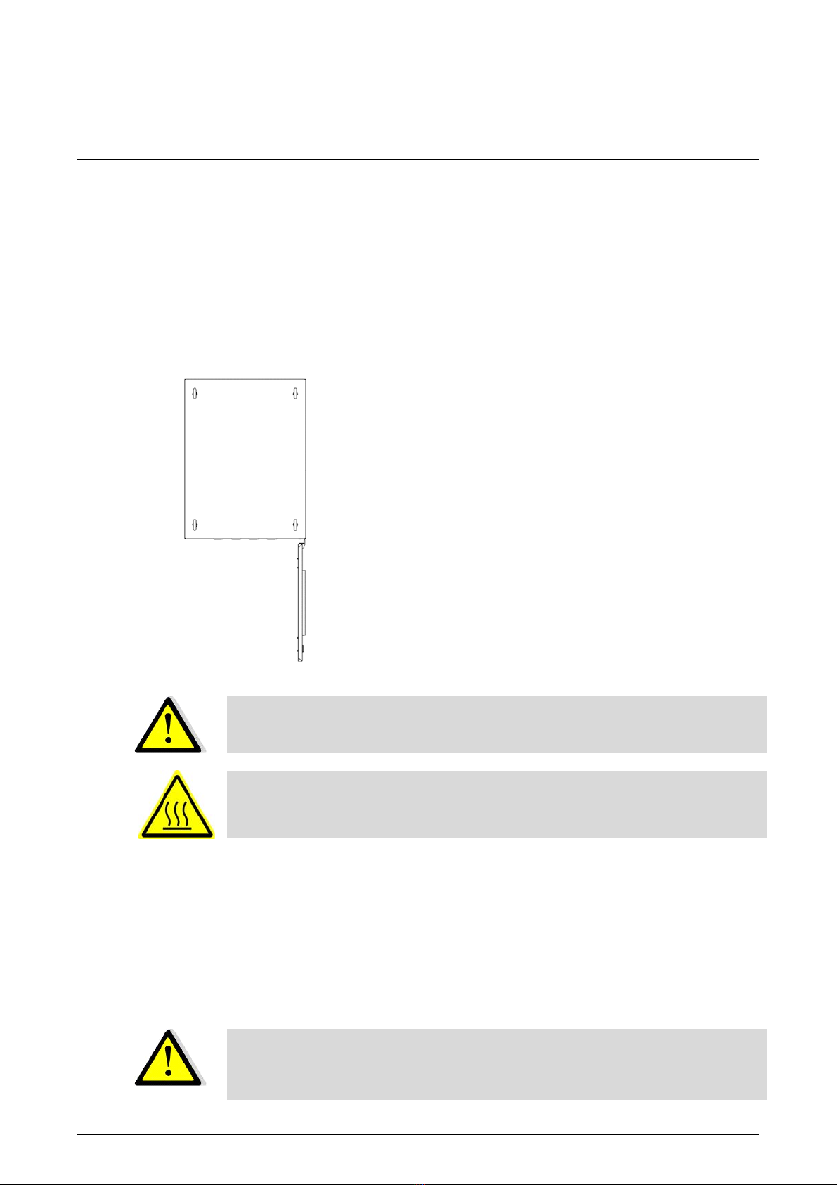
3.2 INSTALLING AND SECURING THE RECTIFIER CHARGER ................. 9
3.3 INSTALLING THE BATTERY ................................................................. 10
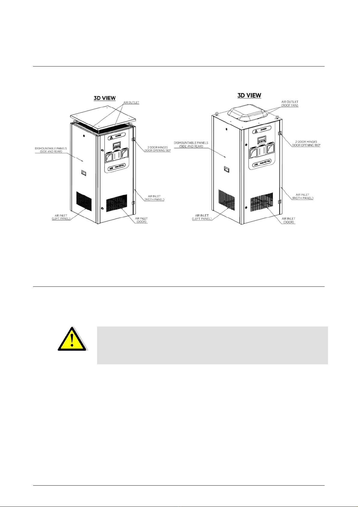
3.4 ENVIRONMENTAL REQUIREMENTS (EXCLUDING THE BATTERY) 10
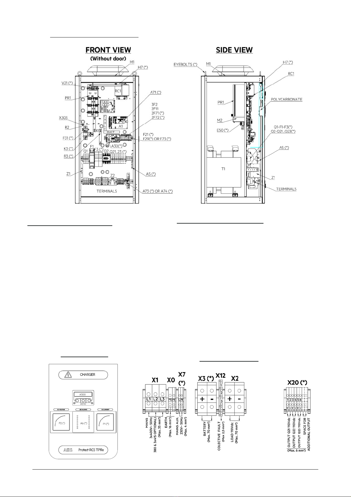
4 CONNECTIONS (refer to the PRODUCT drawing) ...................... 11
4.1 MAINS INPUT CONNECTION ............................................................... 11
4.2 BATTERY CONNECTION ...................................................................... 12
4.3 CONNECTING THE COMMON REMOTE ALARM OUTPUT ................ 12
4.4 CONNECTING THE LOAD .................................................................... 13
5 START-UP (refer to the product drawing) ..................................... 13
5.1 PRELIMINARY CHECKS ....................................................................... 13
5.2 SWITCHING ON ..................................................................................... 14
5.3 START-UP PROCEDURE OF TPRE TD PARALLELED SYSTEMS ..... 15
5.4 BATTERY COMMISSIONING CHARGE ................................................ 15
6 OPERATING INSTRUCTIONS ..................................................... 16
6.1 DEFAULT MENU .................................................................................... 16
6.2 MAIN MENU ........................................................................................... 16
6.3 HUMAN INTERFACE STRUCTURE ...................................................... 18
6.4 STATUS INDICATION DISPLAY ........................................................... 18
6.5 MONITORING FUNCTION ..................................................................... 19
6.6 COMMAND FUNCTION ......................................................................... 22
6.7 CONFIGURATION FUNCTIONS ........................................................... 29
7 FUNCTIONAL DESCRIPTION ..................................................... 34
7.1 OPERATING SEQUENCES ................................................................... 34
7.2 CHARGE MODES .................................................................................. 35
7.3 PRINCIPLE OF OPERATION ................................................................ 35
7.4 "GCAU" GENERIC CONTROL AND ALARM UNIT (A1) ....................... 36
7.5 "TPC" THREE- PHASE CONTROL BOARD (A2) .................................. 36
7.6 DISPLAY BOARD (A300) AND KEYBOARD ASSEMBLY (A310) ......... 37
8 OPTIONS ...................................................................................... 37
8.1 ALARM/SIGNALLING/MEASUREMENT OPTIONS .............................. 37
8.2 COMMUNICATION OPTIONS ............................................................... 39
8.3 LOAD OPTIONS ..................................................................................... 40
8.4 BATTERY OPTIONS .............................................................................. 40
8.5 CABINET OPTIONS ............................................................................... 43
9 PARALLEL OPERATION .............................................................. 44
9.1 REDUNDANT SYSTEM CONFIGURATION .......................................... 44
9.2 PARALLEL SYSTEM CONFIGURATION .............................................. 44
9.3 OPTIONS FOR PARALLEL SYSTEM CONFIGURATIONS .................. 44
10 MAINTENANCE ............................................................................ 45
10.1 PREVENTIVE MAINTENANCE VISIT .................................................... 45
10.2 FAN MAINTENANCE ............................................................................. 46
10.3 CAPACITORS MAINTENANCE ............................................................. 46
11 ELEMENTARY TROUBLESHOOTING ........................................ 46

- 4 / 50 - BN 09 2671/01/01
1 INTRODUCTION
This manual is designed to familiarize the user with the operating principles, use and maintenance of the PROTECT
RCS TPRe TD range of rectifiers fitted in floor mounted cabinets. TPR means Three Phase Rectifier and "e" means
"evolution" brought by the GCAU control card. TD means that this range is designed to fulfill the electrical energy
Transmission and Distribution (T&D) market specifications, although it can be used in other applications provided
that the related specifications and rules are compatible.
To use the system properly, the user should first read this manual carefully.
AEG is not be responsible for damage due to improper use, neglect, alterations, or use of other than original parts
without our written consent.
Equipment access areas:
- Operator: door closed.
- Maintenance personnel: door open.
IMPORTANT RECOMMENDATIONS:
ANY OPERATION ON THE EQUIPMENT SHOULD BE CARRIED OUT BY QUALIFIED PERSONNEL,
AWARE OF SPECIFIC ELECTRICAL HAZARDS AND PRECAUTIONS TO BE TAKEN.
LETHAL VOLTAGES EXIST PERMANENTLY ACROSS THE BATTERY TERMINALS.
DO NOT MAKE ASSUMPTIONS AS TO THE PRESENCE OR ABSENCE OF A VOLTAGE: CHECK
USING A VOLTMETER OR AN ELECTRICAL SAFETY TESTER.
WEEE INFORMATION
The disposal of this product is covered by a selective processing of some components. For
this provision of services, please contact our Customer Service.
Refer to standards 2002/95/EC (LSDEEE or RoHS) and 2002/96/EC (WEEE)
Forgeneralinformationaboutoperatingprinciplesofthecharger:pleasereferfirsttoChapter7"Functional
description".
SYSTEM DRAWINGS:
This manual comes with a standard drawing package.
These documents will be needed for any operation at site.
All the documents are accessible on AEG Power Solution download center web site, the link to this
site is available on the system.

- 5 / 50 - BN 09 2671/01/01
2 PRESENTATION OF THE SYSTEM
The battery charger is composed of the following items :
1. Floor standing cabinet with air inlets and outlets, including a natural cooling and a fan forced cooling roof
depending on the system rating
2. Charger electrical components on a mounting plate
3. Mains transformer
4. Options depending on the system configuration
The door of the cabinet is equipped with the man-machine interface (MMI) allowing the operation and monitoring
of the system.
Cabinet with natural cooling roof Components internal mounting plate (door open)
The PROTECT RCS TPRe TD range offers the following standard ratings and cabinet cooling features :
PROTECT RCS TPRe TD
BATTERY
V
OLTAGE (VDC)
24 36 48 60 110 125/127
Output current (A)
Cabinet cooling :
N=natural
F = forced
Cabinet weight (kg)
20A
(N)
110kg
20A
(N)
110kg
20A
(N)
120kg
20A
(N)
120kg
20A (N)
220kg 20A (N)
220kg
25A
(N)
110kg
25A
(N)
110kg
25A
(N)
120kg
25A
(N)
120kg
25A (N)
220kg 25A (N)
220kg
40A
(N)
120kg
40A
(N)
120kg
40A
(N)
140kg
40A
(N)
140kg
40A (N)
240kg 40A (N)
240kg
60A
(N)
140kg
60A
(N)
140kg
60A
(N)
160kg
60A
(N)
160kg
60A (N)
260kg 60A (N)
260kg
100A
(N)
160kg
100A
(N)
160kg
100A
(N)
180kg
100A
(N)
180kg
100A
(F)
280kg
100A (F)
280kg
“N means cabinet natural cooling, “F” means cabinet fan forced cooling
Air inlets MMI Front door options Charger mounting
plate and options Front door
options
Transformer behind
the mounting plate

- 6 / 50 - BN 09 2671/01/01
Charger internal layout description :
Charger standard components :
Input/output terminal block (X1-X2)
Mains input EMC filter (Z1) depending on
charger rating
Mains input breaker (Q1)
Mains input transformer (T1)
Rectifier bridge (PR1) – can be equipped with a
cooling fan depending on charger rating
Rectifier shunt (R2)
Rectifier output protection fuse (F1)
Filter capacitor (C1) with discharge resistor
Load output switch (Q2)
GCAU control card (A1)
Thyristor intarfe card (A2)
Cooling fan on some ratings (M1)
Common alarm terminal block (X12)
Charger options (marked with (*)
Analog rectifier output ammeter (P1)
Analog rectifier output voltmeter (P2-F21)
Front panel alarm LEDs (A6)
8 relays alarm card (A5)
RS485 modbus communication (A71)
TCP/IP communication for SNMP or Modbus over IP (A73)
IEC61850 communication (A74)
Internal DC power supply (A30) to energize
communication options
Internal lighting (H7) protected by F71, connected on X7
Anti-condensation heater (E50) protected by F72,
connected on X7
Blocking diode for paralleling (V21)
3x outgoing feeders (Q21-Q22-Q23) connected on X20
Battery output (X3-F3-K3-R3)
Battery temperature sensor with 5m cable (SD1)
Lifting eyes M10 – Qty 2
Front door details
Terminal block details

- 7 / 50 - BN 09 2671/01/01
3 INSTALLATION
The system is delivered as shown hereafter.
Natural cooling cabinet Forced cooling cabinet
The equipment is fixed onto a pallet.
3.1 HANDLING
The equipment must be handled with care, always in a vertical position. Labels on the outside of the package show
the top and bottom.
CAUTION:
The transport of the system can be performed as follows:
- on pallet,
- by crane (in presence of lifting eye bolts),
- b
y
forklift
truck.

- 8 / 50 - BN 09 2671/01/01
The TPRe TD rectifiers are delivered on pallets for easy handling using a pallet truck.
For the transport of cabinets, always watch for the center of gravity.
Check that the eye bolts are screwed fully home. The length of the slings calculated so that a minimum angle is
given between the cable and the top edge of the cabinet. The total weight shall be equally balanced between all
the slings. The minimum capacity of each sling must be 0.5 times the weight of the cabinet. One sling must be
used for each eyelet.
The lifting capacity of the handling equipment used must always be greater than the weight of the cabinets
(specified on the packages).
In case of vermin proof plate on the floor, the cabinet must be installed using slings.
CAUTION:
- Only transport the cabinets in an upright position!
- Never tilt or cant, always observe the centre of gravity!
- Always keep the battery cells in a vertical position.
- Never lift a battery cell by its connections.
- Do not put or drop objects on the battery.
- Do not stay or walk under suspended loads.
- Always wear protective clothings and accessories.
Instuctions for lifting using the eye bolts :
Cabinet with 4 lifting eye bolts Cabinet with 2 lifting eye bolts

- 9 / 50 - BN 09 2671/01/01
3.2 INSTALLING AND SECURING THE
RECTIFIER CHARGER
Select an installation site with the following characteristics:
- Ambient temperature and relative humidity as specified in section 3.4.
- Ambient air free from dust and corrosive gases.
- Floor sufficiently flat.
- Floor sufficiently strong to carry the weight of the equipment.
- Sufficient space at the front to open the door (see picture below).
- So that the cabinet will not be distorted, some wedges can be used to ensure the mechanical interface
between the floor and cabinet fixations. This ensures a correct tightening torque.
- For the distances between hole centre, the location and the diameter of the fixing holes, refer to the
customer drawings.
CAUTION:
Securing the cabinets to the floor is recommended.
CAUTION:
Do not touch the metal section near the heating resistor.
Do not touch the rectifier bridge heatsinks.
Installing a single cabinet :
- For the distances between floor fixing hole centers, the location and the diameter of the floor fixing holes, refer
to the product drawings.
- Mark the cabinet position on the floor.
- Perform the drillings (four holes).
- Position the cabinet.
- Fix the cabinet to the floor.
CAUTION: Make sure that a minimum distance of 100mm is available on both sides in
order to have a correct air intake on the side panels ventilation meshes and to ensure a
proper cabinet cooling.
The maximum door opening is 180°.
The minimum door opening in order to
carry out the maintenance tasks is 120°.

- 10 / 50 - BN 09 2671/01/01
3.3 INSTALLING THE BATTERY
The ground or floor must be strong enough to carry the weight of the batteries and/or stands or cabinets in which
they are mounted.
3.4 ENVIRONMENTAL REQUIREMENTS
(EXCLUDING THE BATTERY)
Storage in standard carboard packing box
Temperature: - 25°C to +70°C
Relative humidity: 15% to 90% in the original package.
Maximum storage period: 3 months.
Storage in seaworthy packing
Temperature: - 25°C to +70°C
Relative humidity: 15% to 90% in the original package.
Maximum storage period: 12 months.
For a storage period exceeding the values recommended above, contact the factory in order to know the
required environmental conditions and the maximum storage duration.
Operating
Temperature: 0°C to +50°C
Above 50°C and up to 55°C, the output current must be de-rated (1.25% per °C).
Relative humidity: 20% to 95 % (non-condensing).
Altitude
1000 m
Above 1000 m and up to 4000 m, the output current must be de-rated (7% per 1000 m).

- 11 / 50 - BN 09 2671/01/01
4 CONNECTIONS (REFER TO THE PRODUCT
DRAWING)
ANY OPERATION ON THE EQUIPMENT SHALL BE CARRIED OUT BY QUALIFIED
PERSONNELAWAREOFSPECIFIC ELECTRICALHAZARDS ANDPRECAUTIONS TO
BE TAKEN. NEVER ASSUME THE ABSENCE OF VOLTAGE, ALWAYS CHECK WITH
A VOLTMETER BEFORE ANY OPERATION ON A SYSTEM.
Always make the connections with power off and the circuit-opening devices in the "open"position:
- Mains and load protective devices or disconnecting switch open.
- Battery protective device or disconnecting switch open.
- Power switch to "OFF" (option).
Ifan external protectionor cut-offdevice ismounted betweenthe charger outputand
the battery shunt, it is necessary to provide an auxiliary contact "position open" of
this device to open the battery current measurement to avoid damaging the control
system.
The external battery shunt must be inserted on the negative polatity of the battery,
never on the positive polarity as this will damage the charger control board.
Please contact AEG Power Solutions Customer Service Department.
4.1 MAINS INPUT CONNECTION
DANGER, IF THE RECTIFIER IS EQUIPPED WITH AN OPTIONAL INPUT FILTER:
MAINS INPUT: HIGH LEAKAGE CURRENT.
EARTH CONNECTIONIS MANDATORYBEFORE CONNECTINGTHEMAINSSUPPLY.
It is mandatory to install a mains input protection in the mains switchboard, upstream the charger.
Recommended rating: 2 x charger nominal input current.
- The nominal input current is specified on the electrical characteristics page of the customer drawing package.
- As standard, the inrush current is less than 20 times the input current.
Connect the mains input to the terminal block located in the connection area.
The Protect RCD TPRe TD units are not phase rotation sensitive.
Remember to connect the earth bar to the site reference earth.

- 12 / 50 - BN 09 2671/01/01
4.2 BATTERY CONNECTION
IMPORTANT RECOMMENDATIONS
REFER TO THE BATTERY MANUAL.
Refer to the battery manufacturer's instructions for the storage conditions.
Never short-circuit a battery.
IN ANY CASE, a battery short-circuit and overcurrent protection must be
connectedbetween thebattery andthechargerifthechargerisnotequippedwith
such a protective device.
Allow no flame nor sparks in the battery room. Never smoke in the battery room.
Never disconnect a battery being charged.
To handle the electrolyte, use gloves and safety goggles.
The electrolyte contained in a battery is dangerous to the skin and clothes.
Before doing work on a battery, make sure that there is an accessible supply of
water nearby. If electrolyte is splashed, wash immediately with water and refer to
battery safety data sheets.
Use tools with insulated handles.
Remove the shipping plugs from "open" Ni-Cd batteries. Always use
maintenance accessories (especially electrolyte handling tools) suited to the
batteries.
Reminder
Battery cells must be connected in series, the(+) pole of each cell must be connected to the(-) pole of the next one.
+ - + - + - + - + -
- + - + - + - + - +
BATTERY (+)
BATTERY (-)
Series connection of battery cells
Battery installation procedure :
. Position the battery cells on their support and connect them in series.
. Check that no cell is missing.
. Check that the connections are tight.
. Connect the battery (-) to the (-) BATT terminal of the charger (via the fuse box if applicable).
Do not connect the positive cable until start-up time.
4.3 CONNECTING THE COMMON REMOTE
ALARM OUTPUT
Refer to the customer drawing package.

- 13 / 50 - BN 09 2671/01/01
4.4 CONNECTING THE LOAD
Connect the load (+) to the load (+) terminal of the equipment.
Connect the load (-) to the load (-) terminal of the equipment.
5 START-UP (REFER TO THE PRODUCT
DRAWING)
5.1 PRELIMINARY CHECKS
All circuit-opening devices must be in the "open" position.
Check that the mains line protective device rating has the appropriate rating (see section 4.1).
Check that the mains voltage and frequency are compatible with the equipment (see equipment nameplate).
Check that the mains, battery and load connections are tight.
Check the polarities and that the battery cells are correctly connected in series.

- 14 / 50 - BN 09 2671/01/01
+ BATT
- BATT
V
+-
-
F13
+
-
LOAD
F1
+ BATT
- BATT
V
+-
F14
+
-
LOAD
F1
5.2 SWITCHING ON
- Leave the positive side of the battery open, either through protective or opening device (e.g.
fuse F13: case 1 below) or through the battery cable not connected to the (+) BATT terminal of the charger (case
2 below).
- Close the negative side of the battery (-) (fuse, protective device, etc … ).
- Close the mains protective devices. Turn on the mains input and the rectifier.
The rectifier starts and the display shows:
V x.y.z = software version of the display controller
After a few seconds, the display shows:
Vxx.yy and aa.bb are the software versions of the
two micro controllers of the GCAU board
After a few seconds, the display shows the floating voltage and the rectifier current (at no-load).
NOTA: The current value can be around 0.5 A.
To check that the battery polarities are correct, take a voltage reading using a DC voltmeter as shown below:
- Case 1 - - Case 2 -
Configuration with battery fuse F13 Configuration without opening device
The voltage reading must not exceed 30% of the nominal voltage (refer to the customer drawings).
. If the voltage is outside of this tolerance, check the battery cables for correct polarity.
. If the voltage is correct, close fuse F13 or connect the battery (+) cable to the rectifier terminal. The rectifier
will charge the battery. During this operation, arcing may develop across the actuated device.
- Check that the displayed current increases (current to the battery).
AEG PS-GCAU
V
xx.
yy/
aa.bb
DC:xx.x
V
0.5A
Alarms:
DC:xx.x
V
3.0A
v x.y.z

- 15 / 50 - BN 09 2671/01/01
Dangerous voltages exist across the battery and/or load terminals. Take the
necessary safety precautions.
We recommend to change “user” and “supervisor” passwords to prevent bad
handlings. Refer to paragraph 6.7.3.
5.3 START-UP PROCEDURE OF TPRE TD
PARALLELED SYSTEMS
In the case of TPRe TD units with battery (each one) connected in parallel for redundancy, respect the following
instructions :
- Check that the output protective device of each unit is open.
- Start-up the rectifier-battery assembly n°1 according to the previous paragraph 5.2.
- Start-up the rectifier-battery assembly n°2 according to the previous paragraph 5.2
Then close the output protective device of each unit.
5.4 BATTERY COMMISSIONING CHARGE
For open lead-acid and Nickel-Cadmium batteries, at initial start-up, a commissioning charge can be performed
according to the battery manufacturer's instructions (refer to the battery manual).
Open load circuit.
From the command menu, set the rectifier to the commissioning charge (refer to paragraph 6.6.2).
The initial start-up current and time are factory set. Refer to the "System setup" menu (refer to paragraph 6.7.3.2)
to see the adjustment value.
At the end of the commissioning charge:
- from the "Alarm" menu, reset the "HIGH DC VOLTAGE" alarm. This alarm can be triggered when
returning from commissioning charge to floating charge.
WARNING : as the commissioning charge voltage is higher than the usual floating
and high rate charge levels, make sure that the DC output loads are disconnected
from the battery and charger before initiating the commissioning charge.

- 16 / 50 - BN 09 2671/01/01
6 OPERATING INSTRUCTIONS
The following section explains the basic operator menu structure of your system. It allows you to access all
necessary functions in order to operate your system.
The menus, indications and controls available depend on the system configuration.
The keyboard assembly has two LEDs indicators:
green LED: "System OK" (indicates proper operation).
red LED: "Fault" (a fault is present).
The green LED is always on in case no alarms are present.
In case an alarm is present, the red LED comes on and flashes.
If the alarm is acknowledged, the red LED is on permanently provided the alarm is still active.
If no alarms are active after an acknowledgement, the red LED will be switched off and the green LED comes on
again.
6.1 DEFAULT MENU
The top line ("DC") will display the charger voltage and the load current with battery shunt or the total charger
current (battery + load) when the battery shunt is not active.
Hit any key to go to main menu
6.2 MAIN MENU
The different rectifier statuses are:
- FLOATING CHARGE
- HIGHRATE CHARGE
- COMMISSIONING
- CHARGER OFF (see Chapter 11 "ELEMENTARY TROUBLESHOOTING for more explanations)
- BATTERY TEST.
DC
:
XX.XV
XX.XA
FLOATING CHARGE
Monit Confg Cmnd
Output informations
DC output voltage value
DC output current value (this
display value can be
customized )
Number of alarms
Left key menu
Middle key menu
Right key menu
Alarms information
Rectifier status
More than 1 line can be displayed
In this case, end is shown with
“--END OF LIST--” message Menu keys

Main menu
Configure
Monitoring
Hit any key
Command
Measurements
Alarm list
History list
Set language
Set date and time
Setup
Left ke
y
menu
Middle ke
y
menu
Right key menu
Set high rate
/
floatin
g
Set commissioning
/
floatin
g
Manual adjustment
Battery test
Clear history
Reset AH meter
Adjust contrast
Available only in charger mode
Available only in power supply mode
Output voltage, battery current, load voltage, AC voltage, battery temperature, ambient
temperature, battery charge, charger timer, date and time
Password *
(
if activated
)
Alarm text, “RESET” alarm
Events and alarms text with date, time, and set point
System setup
Calibrate setup
Alarm setup
Password *
(
if
act
iv
ated)
Password *
(if activated
)
Password *
“Supervisor”
p
assword
“User”
pass
w
o
r
d
Nominal settings, highrate options,
battery selection, password setting…
Activate high rate or floating charge
Activate commissioning or floating charge
Activate or deactivate battery test
Clear history entries
- Menu overview -
Reset at 100% battery charge level
+/- LCD contrast adjust
Password
*
English or your local language
Enter hour, minutes, month, day and year
Voltage and current power supply adjustment
Access usually granted with "Supervisor" password
only (access rights are factory configurable)
Default menu
5 minutes inactivity
see § 6.5.1
see
§
6.5.2
see § 6.1
see § 6.2
see § 6.5
see
§
6.7
see § 6.6
see
§
6.5.3
see
§
6.7.1
see § 6.6.1
see
§
6.6.2
see
§
0
see
§
6.6.
5
see
§
6.6.6
see § 6.6.7
see § 0
see
§
6.7.2
see
§
6.7.3
* “User” or “supervisor” password
Note: According to your equipment configuration, some menus may be inactivated.
Calibrate voltage, temperature,
ground fault…
Low/high voltage, current,
s
p
are in
p
uts…
Access granted with "Supervisor"
password only (access rights are not
configurable)
Access usually granted with "User" (partly)
and "Supervisor" passwords (access rights
are factory configurable)
“Factory”
p
rotected level
- 17 / 50 - BN 09 2671/01/01

BN 09 2671/01/01 - 18 / 50 -
6.3 HUMAN INTERFACE STRUCTURE
The human interface is based on consistency in operation. Consistency means that the functions are grouped
logically within the menu structure and will provide ease of use for the operator.
The LCD Display has 2 lines by 16 characters. The top line is always used to indicate information while the bottom
line is used for the menu structure indication.
There are three major menu groups under which all functions are located.
These groups are defined as:
Monitoring Displaying analog measurements and alarms
Configuration Configuring the system
Commands Manually activated functions (High rate, Battery test etc.)
The menu indication uses five basic menu functions with the following functions:
Next One step forward in the menu
Back One step back in the menu
View Display a selection
Enter Acknowledge an entry
Exit Always return to default menu
The following sections will clearly explain how you can access the various functions.
6.4 STATUS INDICATION DISPLAY
As explained in the previous chapter the top line of the display will indicate information about the status of the
system. If more than one message is active, the messages are displayed in sequence. Each message is displayed
for 1 second before the next message is displayed.
The following messages are displayed:
Alarm texts of the active alarms
Charge status messages
Events
Information line
The messages are dynamic meaning they are updated continuously. If the alarm texts are latched you must go into
the alarm menu to clear the text from the display. Refer to section 6.5.2 for details.
XXXXXXXXXXXXXXXX
Monit Confg Cmnd
XXXXXXXXXXXXXXXX
Next Back Exit XXXXXXXXXXXXXXXX
Next View Exit
X
XXXXXXXXXXXXXXX
Next Enter Exit
XXXXXXXXXXXXXXXX
Monit Confg Cmnd
Information line
Menu Line
FLOATING CHARGE
Monit Confg Cmnd

- 19 / 50 - BN 09 2671/01/01
6.5 MONITORING FUNCTION
6.5.1 How to Display the Measurements
You will find the measurements menus under the Monitoring function. The Monitoring function will display all relative
meter indications on the top line of the LCD.
Follow the instructions below.
The top line ("Outp") will display the battery voltage and the total charger current (battery + load).
Display resolution is 1 decimal for V and A <100 and no decimal for values > 100.
In order of appearance the following measurements can be displayed:
Load voltage and current*
Battery current (charge and discharge)*
Battery voltage and total charger current
AC input voltage*
Battery temperature*
Ambient temperature*
AH Meter*
Remaining charge time* (if in High rate or Commissioning charge)
Date and Time
Customized measurements (depends on system configuration)
* Menu can be disabled on customer demand.
FLOATING CHARGE
Monit Confg Cmnd
MEASUREMENTS
Next
V
ie
w
Exit
Outp:28.4V 23.5A
Next Back Exit
From the main menu select ‘Monit’.
Select ‘View’.
The ‘Next’ key can be used to scroll through all available
measurements.

BN 09 2671/01/01 - 20 / 50 -
6.5.2 How to Display the Alarm List
You will find the Alarm list indication under the Monitoring function. This Alarm List indication will display all active
alarms on the top line of the LCD.
Follow the instructions below.
The display indication XX shows you how many alarms are in the alarm list. The list shows Active alarms and Non-
acknowledged (Reset) alarms based on the alarm configuration. If a “LCD Latch” function is selected for an alarm,
it will remain in the alarm list even if the alarm condition has disappeared. In this case, a manual alarm reset will
clear it from the alarm list.
Select ‘View’.
The alarm is shown in clear text on the top line. Pressing ‘Next’ will show you the next alarm in the list and pressing
‘Back’ will show you the previous alarm in the list.
If an alarm has not been acknowledged the text 'Reset' will flash. If the alarm is acknowledged and the alarm option
“LCD latch” was activated (see Alarm Setup for details), the alarm will be removed from the list provided the
condition of the alarm has been cleared.
If an alarm is associated with a signalling relay with latching, the display of this alarm is imperatively "latch" set.
The acknowledgment of the alarm using the display causes the acknowledgment of the associated relay too.
FLOATING CHARGE
Monit Conf
g
Cmnd
MEASUREMENTS
Next
V
iew Exit
Alarm List: XX
Next
V
ie
w
Exit
LOW DC VOLTAGE
Next Back Reset
From the main menu select ‘Monit’.
Select ‘Next’.
Table of contents
Other AEG Batteries Charger manuals
Popular Batteries Charger manuals by other brands

Draper
Draper BCD12 instructions

Alpina
Alpina BT 40 Li 2.0 Operator's manual

Webasto
Webasto Next Operating and installation instructions

Conceptronic
Conceptronic OZUL04BE Quick installation guide

Intos Electronic
Intos Electronic InLine Qi Powerstation Multiport operating instructions

KOSTAD
KOSTAD CPC 50 operating instructions