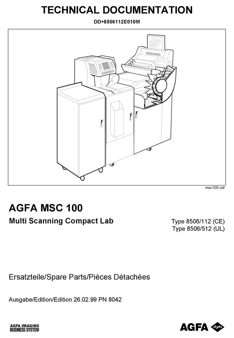
AGFA Avantra 36/44 User manual

The Avantra 36/44
Service Manual
Part Number
580078-0002

AVANTRA 36/44
Service Manual
This document discloses subject matter in which
Agfa Division, Bayer Corporation has proprietary
rights. Neither receipt nor possession thereof
confers or transfers any right to reproduce or disclose
the document, any part thereof, any information
contained therein, or any physical article or
device, or to practice any method or process,
except by written permission from or written
agreement with Agfa Division, Bayer Corporation.
COPYRIGHT ©, 1996, 1997
Agfa Division, Bayer Corporation
Prepared by
Customer Documentation
200 Ballardvale Street
Wilmington, MA 01887
Printed in the U.S.A.
580078-0002

Table of Contents iii
Table of Contents
INTRODUCTION
About This Manual.........................................................................................xiii
Warnings, Cautions, and Notes .....................................................................xiii
Imagesetter Safety Information .....................................................................xiv
Laser Safety.................................................................................................xiv
Labeling.......................................................................................................xv
On-Line Processor (OLP) Safety Information...............................................xvi
Service Manual Audience ..............................................................................xvii
Manual Overview .......................................................................................xvii
Product Description.......................................................................................xx
GLOSSARY OF ACRONYMS
Glossary of Acronyms....................................................................................xxiii
SECTION 1: IMAGESETTER
Chapter 1: Imagesetter Installation Procedures
Introduction....................................................................................................1-1
Customer Pre-site Checklist...........................................................................1-1
Service Engineer Installation Procedure.......................................................1-4
Pre-installation Checks...............................................................................1-4
Unpacking the Imagesetter........................................................................1-5
Unlocking and Installing the Imagesetter .................................................1-13
Checking the System......................................................................................1-22
Customer Application Training .....................................................................1-24
Chapter 2: Imagesetter Functional Analysis
Introduction....................................................................................................2-1
System Overview ...........................................................................................2-3
Electronics Overview.....................................................................................2-3

Avantra 36/44 Service Manual
iv Table of Contents
Electronics Packaging.................................................................................2-4
System Architecture....................................................................................2-4
Digital Engine Controller (DEC)....................................................................2-7
Operator Control Panel .................................................................................2-8
Micro-controller..........................................................................................2-9
OCP FLASHROM ........................................................................................2-9
Liquid Crystal Display (LCD).....................................................................2-10
Keypad........................................................................................................2-10
OLP/Bridge Interface .................................................................................2-10
Speaker (Audio Interface)..........................................................................2-10
Carriage Sensor Driver Module (CSDM).......................................................2-10
Sensor Driver Module (SDM)........................................................................2-11
SDM to DEC Interface................................................................................2-12
Laser Driver Module (LDM)...........................................................................2-13
Power Supply.................................................................................................2-14
Additional Voltages.....................................................................................2-14
Power Distribution .....................................................................................2-14
Power Good ...............................................................................................2-14
Optical System Overview..............................................................................2-15
Spot Generation Module ...............................................................................2-16
Laser Diode Mount.....................................................................................2-17
Polarizer......................................................................................................2-17
Spot Size Changer ......................................................................................2-17
Spot Forming Lens .....................................................................................2-17
Weak Lens...................................................................................................2-18
Beam Compressor......................................................................................2-18
Spin Motor Module........................................................................................2-18
Spin Motor ..................................................................................................2-19
Mirror ..........................................................................................................2-19
Encoder.......................................................................................................2-19
Linear Carriage Transport Overview.............................................................2-19
Carriage Assembly......................................................................................2-19
Linear Bearing Guideway ..........................................................................2-21
Carriage Home Position Sensor.................................................................2-21
Inner Shrouds .............................................................................................2-21
Vacuum System...........................................................................................2-23
Media Transport System Overview...............................................................2-25
Table of Contents
Table of Contents v
Supply Side Mechanics...............................................................................2-26
Powered Media Take-up Cassette .............................................................2-27
Media Punch/Clamp Assembly..................................................................2-28
Take-up Drive Assembly............................................................................2-29
Media Cutter Assembly...............................................................................2-31
Supply Cassette...........................................................................................2-32
Humidifier Option Overview ........................................................................2-34
General Description ...................................................................................2-34
Humidifier Sub-assembly ...........................................................................2-34
Humidifier Electronics Module..................................................................2-35
Fan Control Circuit .....................................................................................2-36
Interface Connections.................................................................................2-37
Software Functionality................................................................................2-37
Humidifier PC Board: LED Descriptions...................................................2-37
Humidifier Option: Warnings and Indications .............................................2-38
Humidity Low Indicator.............................................................................2-38
Water Supply Empty Alert..........................................................................2-38
Chapter 3: Imagesetter Diagnostics and Vacuum System
Troubleshooting Guide
Introduction....................................................................................................3-1
Power-up Boot Diagnostics...........................................................................3-2
Power-up Boot Diagnostics Overview......................................................3-2
Power-up Boot Sequence ..........................................................................3-3
Error Reporting...........................................................................................3-5
Automatic Dial-out Feature........................................................................3-11
Boot Error Codes........................................................................................3-13
OCP Run-Time Application Errors.............................................................3-15
Avantra Diagnostic Program (PC) .................................................................3-17
Equipment Requirements...........................................................................3-17
Software Installation...................................................................................3-18
Starting the Program...................................................................................3-19
Save and Restore System Parameters ........................................................3-49
Remote Diagnostics........................................................................................3-61
Equipment Requirements...........................................................................3-61
Hardware Configuration.............................................................................3-63
Vacuum System Troubleshooting Guide.......................................................3-67
Volt Sensing Relay Adjustment Procedure ................................................3-71

Avantra 36/44 Service Manual
vi Table of Contents
Chapter 4: Imagesetter Component Removal/Replacement
Procedures
Introduction....................................................................................................4-1
Covers.............................................................................................................4-3
Right/Left Side Covers................................................................................4-3
Top, Middle and Bottom Front Panels......................................................4-5
Electronic Enclosure Cover........................................................................4-8
Media Transport Removal/Replacement Procedures...................................4-9
Take-up Light Shield ..................................................................................4-9
Outer Take-up Drive (Nip) Assembly.......................................................4-10
Inner Take-up Drive (Nip) Assembly........................................................4-11
Inner Take-up Drive (Nip) Motor..............................................................4-14
Take-up Jam Sensor ...................................................................................4-16
Take-up Punch Assembly ..........................................................................4-18
Cutter Assembly..........................................................................................4-20
Cutter Motor................................................................................................4-22
Take-up Media Present Detector...............................................................4-23
Supply Jam and Media Present Sensors....................................................4-24
Electrical Removal/Replacement Procedures ...............................................4-25
Digital Engine Controller (DEC) PCB........................................................4-25
Carriage Sensor Driver (CSDM) PCB.........................................................4-28
Operator Control Panel Assembly.............................................................4-30
The Supply and Take-Up Sensor Driver Modules PCB (SDMs) ..............4-32
Power Supply .............................................................................................4-34
Main Power Switch.....................................................................................4-36
Exhaust Fan ................................................................................................4-38
Intake Fan...................................................................................................4-39
Carriage Drive Removal/Replacement Procedures ......................................4-40
Carriage Transfer Tool Installation ............................................................4-40
Carriage Assembly......................................................................................4-42
Opto-mechanical Removal/Replacement Procedures..................................4-45
Light Shields (Right and Left).....................................................................4-45
Spin Motor Module (SMM).........................................................................4-47
Spot Generation Module (SGM)................................................................4-49
Spot Size Sensor .........................................................................................4-50
Polarizer Sensor..........................................................................................4-51
Beam Compressor Motor...........................................................................4-52

Table of Contents
Table of Contents vii
Aperture Wheel Motor ...............................................................................4-53
Weak Lens Motor........................................................................................4-54
Focus Sensor...............................................................................................4-55
Media Transport Removal/Replacement Procedures ...................................4-57
Supply Drive Servo Motor..........................................................................4-58
Supply Cassette A or B Rewind Motors ....................................................4-61
Supply Spindle Select Motor......................................................................4-62
Supply Spindle Select A/B Sensors............................................................4-64
Supply Roller Removal and Installation ....................................................4-66
The Vacuum System .....................................................................................4-68
Vacuum Pump.............................................................................................4-69
Vacuum Valves............................................................................................4-70
Vacuum Board ............................................................................................4-71
Chapter 5: Imagesetter Alignment
Introduction....................................................................................................5-1
Beginning of Line (BOL) Alignment Procedure...........................................5-2
Exposure Adjustment Procedure...................................................................5-4
Carriage Home Position Alignment Procedure ............................................5-5
Focus Alignment ............................................................................................5-7
System Leveling Procedure............................................................................5-10
Voltage Check Procedure ..............................................................................5-11
Pulse Width Modulation (PWM) Adjustment Procedure..............................5-11
Carriage Encoder Alignment Procedure .......................................................5-14
Supply Motor Offset Alignment Procedure ..................................................5-14
Take-up Cassette Clutch Adjustment Procedure ..........................................5-16
Feed Motor Calibration Test..........................................................................5-17
A/B Roller and Sensor Adjustment ...............................................................5-17
Slack Loop Test Procedure............................................................................5-21
Chapter 6: Imagesetter Preventive Maintenance
Introduction....................................................................................................6-1
General Preventive Maintenance Requirements...........................................6-1
Mechanical Inspection................................................................................6-1
Operational Inspection...............................................................................6-4
Cleaning......................................................................................................6-5
Appendix A: Specifications

Avantra 36/44 Service Manual
viii Table of Contents
Appendix B: Spare Parts
Index
SECTION II: BRIDGE
Chapter 1: Bridge Installation
Introduction....................................................................................................1-1
Removing the Imagesetter Top Cover..........................................................1-2
Attaching the Capture Bar to the Bridge......................................................1-5
Raising and Lowering the Bridge into the Imagesetter ...............................1-7
Attaching the Bridge to the Imagesetter.......................................................1-9
Attaching the Bridge Foot..........................................................................1-9
Attaching the Gas Shocks ..........................................................................1-12
Adjusting the Detent Plate .........................................................................1-14
Aligning the Solid Stops.............................................................................1-17
Setting up the DEC to Bridge/Buffer Interface.........................................1-18
Attaching the Ground Wires......................................................................1-21
Chapter 2: Bridge Functional Analysis
Introduction....................................................................................................2-1
Chapter 3: Bridge Debugger Diagnostic Tool
Introduction....................................................................................................3-1
Setting Up the Debugger Port.......................................................................3-2
Bridge Debugger User Interface ...................................................................3-3
Terminal Code Identifiers ..........................................................................3-3
Bridge Unlock Sequence............................................................................3-3
Bridge States...............................................................................................3-4
Bridge State Responses..............................................................................3-5
Bridge Error Codes.....................................................................................3-5
Bridge Sensor Status...................................................................................3-6
Bridge Parameters ......................................................................................3-7
Bridge/Buffer Commands..........................................................................3-7
Chapter 4: Bridge Component Removal/Replacement
Procedures
Introduction....................................................................................................4-1
Removing and Replacing the Bridge Foot....................................................4-2
Media Purchase Sensor..................................................................................4-3

Table of Contents
Table of Contents ix
Bridge Loop Sensor........................................................................................4-3
Upper Bridge Servo Motor ............................................................................4-4
The Activator Switch......................................................................................4-6
The Bridge Up Sensor ...................................................................................4-7
Bridge Shuttle Motor......................................................................................4-8
Shuttle Light and Heavy Sensors...................................................................4-10
Appendix A: Spare Parts
Index
SECTION III: BUFFER
Chapter 1: Buffer Installation
Introduction....................................................................................................1-1
Buffer Installation Procedures.......................................................................1-2
Unpacking the Buffer.................................................................................1-2
Unlocking the Buffer..................................................................................1-6
Installing the Buffer to the Imagesetter.....................................................1-10
Aligning the Buffer Carriage ......................................................................1-19
Chapter 2: Buffer Component Removal/Replacement
Introduction....................................................................................................2-1
Buffer Home and Buffer Processor Sensors.................................................2-2
Buffer Purchase Sensor..................................................................................2-3
Buffer Carriage Drive Motor..........................................................................2-4
Buffer Roller Driver Motor.............................................................................2-5
Appendix A: Spare Parts
Index
SECTION IV: ON-LINE PROCESSOR
Chapter 1: OLP Installation
Introduction....................................................................................................1-1
OLP Work Space Requirements.....................................................................1-2
Space...........................................................................................................1-2
Floor Load...................................................................................................1-2
Electrical......................................................................................................1-2
Operational.................................................................................................1-3

Avantra 36/44 Service Manual
x Table of Contents
OLP Unpacking Procedures..........................................................................1-3
Tools Required for OLP Unpacking ..........................................................1-3
OLP Inventory ............................................................................................1-3
Opening and Unpacking the Parts Crate..................................................1-5
Unpacking and Preparing the OLP Engine...............................................1-8
Installation Procedures ..................................................................................1-13
Tools and Equipment Required for Installation...........................................1-13
Attaching the Legs and Feet.......................................................................1-13
Connecting the Water Supply and Drainage.............................................1-15
Connecting The Electrical Supply .............................................................1-17
Leveling and Attaching the OLP to the Buffer..........................................1-20
Attaching the Panels and Covers...............................................................1-24
Chapter 2: OLP Functional Analysis
Introduction....................................................................................................2-1
Description of OLP Boot-up Procedures......................................................2-2
OLP Standby Mode.....................................................................................2-2
Idle Mode....................................................................................................2-2
Ready Mode................................................................................................2-2
Operate Mode.............................................................................................2-2
The OLP Jog Function................................................................................2-3
Electronics......................................................................................................2-3
The LUTH Computer Board (LCB)............................................................2-3
The LUTH Power Board (LPB)..................................................................2-6
The LUTH Motor Board (LMB)..................................................................2-8
The Agfa Terminal Board (ATB)................................................................2-8
Sensors........................................................................................................2-8
OLP Racks ......................................................................................................2-9
Temperature Control..................................................................................2-9
Replenishment............................................................................................2-9
Chapter 3: OLP Component Removal/Replacement
Introduction....................................................................................................3-1
Drive Motor....................................................................................................3-2
CPU-OLP.........................................................................................................3-4
LUTH Motor Control Board...........................................................................3-9
LUTH Rectifier Board (LRB)..........................................................................3-10
Power Board ..................................................................................................3-11

Table of Contents
Table of Contents xi
Circulation Pump ...........................................................................................3-14
Developer or Fixer Replenishment Pumps...................................................3-15
Heating Element.............................................................................................3-17
Wet Section Temperature Sensor ..................................................................3-18
Dryer Section Temperature Sensor ...............................................................3-19
Dryer Blower Motor Assembly......................................................................3-20
Dryer Heater Element.................................................................................3-20
Dryer Blower ..............................................................................................3-23
Entry Rack Assembly .....................................................................................3-26
Drive Belt....................................................................................................3-26
Drive Shaft ..................................................................................................3-27
Chapter 4: OLP Maintenance
Introduction....................................................................................................4-1
Servicing .........................................................................................................4-2
Checking Sensor Operation.......................................................................4-2
Checking Operation of the LCB ................................................................4-3
Checking the Battery..................................................................................4-4
Setting the Jumpers ....................................................................................4-5
Calibrating/Jumper Settings...........................................................................4-6
LUTH Motor Control Board (LMB) 24V DC (P/N 5202Y000100).............4-7
LUTH Motor Control Board (LMB) 180V DC (P/N 5203Y4000200)........4-11
Replenishment Pumps Calibration.............................................................4-12
Troubleshooting.............................................................................................4-14
The Service Program ..................................................................................4-14
Service Program Codes..................................................................................4-16
How to Use the Repair Method Tables.....................................................4-17
Appendix A: Specifications
Appendix B: Spare Parts
Appendix C: Wiring Diagrams
Index
SECTION V: CRANE
Chapter 1: Crane Mounting Instructions
Introduction....................................................................................................1-1
Unpacking the Crane.....................................................................................1-2

Avantra 36/44 Service Manual
xii Table of Contents
Crane Installation Procedures .......................................................................1-3
The Mounting Plate and Boom .................................................................1-3
Mounting the Head ....................................................................................1-7
Chapter 2: Crane Component Removal / Replacement
Introduction....................................................................................................2-1
Crane Removal/Replacement Procedures ....................................................2-2
Crane On/Off Switch..................................................................................2-2
Crane Motor................................................................................................2-7
Crane Slack Safety Switch..........................................................................2-9
Crane Cable ................................................................................................2-10
Appendix A: Spare Parts
Index

Introduction xiii
Introduction
AboutThis Manual
This manual contains all of the information you need to unpack, prepare, and
install the Agfa Avantra 36/44 and 36S/44S imagesetter, bridge, buffer, on-line
processor, and crane.
Warnings, Cautions, and Notes
The terms WARNING, CAUTION, and NOTE have specific meanings in this
manual.
•A
WARNING
advises against certain actions or situations that could result
in personal injury or death.
•A
Caution
advises against actions or situations that could damage equip-
ment, produce inaccuracies, or invalidate a procedure, although direct per-
sonal injury is unlikely.
•A
Note
provides useful information.

Avantra 36/44 Service Manual
xiv Introduction
Imagesetter Safety Information
Laser Safety
WARNING:
Looking directly into the laser beam or laser beam
reflection can cause permanent eye damage.
The Avantra is a class 1 laser radiation device and is harmless during normal
operation. However, during certain system alignments and tests, the laser is
considered a class 3B device. In this classification, the laser can be harmful to
your eyes.
The laser presents no danger as long as the protective covers are in place.
When the protective covers are removed, follow these safety rules:
• Never look directly into the beam.
• Never expose other persons to the laser beam.
• Use caution with tools and other reflective surfaces to prevent laser reflec-
tion.
• Keep the work area well lit.
• Follow the assembly/disassembly procedures precisely. No short cuts.
These procedures are in the Imagesetter section (Section I), Chapter 4,
“Imagesetter Component Removal/Replacement Procedures”.
• Never operate the laser with the covers removed from the Avantra system.
• Promptly report any actual or suspected accidents. The service engineer
must report immediately to a medical facility if he or she experiences any
of the following eye symptoms:
• A visual halo effect
• A change in tearing (eyes wetter or drier than normal)
• A change in the way colors are seen

Introduction
Introduction xv
Labeling
Various warning and compliance labels are attached to the Avantra 36/44.
Multilingual warning label.
Laser class label.
NOTE:
The figure above indicates the class of laser radiation dur-
ing operation and maintenance.
DANGER
LASER RADIATION WHEN OPEN
AVOID DIRECTEXPOSURE TO BEAM
PELIGRO
RADIACION LASER CUANDO SE ABRA
EVITE LA EXPOSICION DIRECTA DEL HAZ
VORSICHT!
LASERSTRAHLUNG TRITTAUS,
WENN DECKEL
GEOFFNET IST!
NICHT DEM STRAHLAUSSETZEN!
DANGER
RAYONNEMENT LASER A L’OUVERTURE
EVITER TOUTE EXPOSITION DIRECTE
AU RAYON
CLASS 1 LASER
LASER KLASSE 1

Avantra 36/44 Service Manual
xvi Introduction
WARNING:
Class 1 lasers are considered safe for operator access
in accordance with the Code of Federal Regulation and international
standards.
CDRH compliance label.
Manufacturer’s identification label.
On-Line Processor (OLP) Safety Information
If the OLP is part of the system, operate using the following safeguards:
• Do not operate the OLP if it is not level.
• Be careful not to touch the dryer when the top cover is removed. The
dryer gets hot during operation and should be allowed to cool before ser-
vicing.
Agfa Division certifies that this product
conforms to all applicable provisions of 21
CFR Subchapter J in effect as of the date of
manufacture.
Wilmington, MA 01887
abc Division
WILMINGTON, MA 01887
U.S.A.
MODEL
PART NO.
SERIAL
VOLTS
AMPERES
WATTS
Hz
MFG.DATE
MADE IN U.S.A.
Location

Introduction
Introduction xvii
• To protect against the hazard of electric shock, do not allow water to run
or spill into the electical compartment or components.
• Before servicing, always disconnect the electric power or unplug the
power cable at the mains.
NOTE:
The OLP has six built-in safety switches, which disconnect
all power whenever the top lids are opened.
• The processor contains a lithium battery.
WARNING:
The battery may explode if mistreated.Do not recharge
or disassemble. Follow local rules for the disposal of lithium batter-
ies.
When handling chemistries, always follow the safety procedures described by the
manufacturers.
Service Manual Audience
This manual is intended for service engineers. It assumes prior knowledge and
experience with the internal workings of an image processor.
Refer to the
Removal/Replacement Procedures
chapters present in each section
before attempting to service the inside of an Avantra 36/44 imagesetter,
processor, bridge, buffer or crane.
NOTE:
The intent of the
Removal/Replacement Procedures
chap-
ters in this manual are not to repair the units to the level of
their individual components (e.g., the chips on the boards).
They provide instructions for replacing modules (e.g., the
control panel assembly, power supplies, motors, sensors,
etc).
Manual Overview
This manual has the following arrangement:
Section I: Imagesetter
Chapter 1: Imagesetter Installation Procedures
Provides installation instruction including unpacking, unlocking, site
preparation and system set-up procedures for the imagesetter.
Chapter 2: Imagesetter Functional Analysis
Presents an overview of the Avantra 36/44 imagesetter and describes the
function of subsystems, modules, and submodules.

Avantra 36/44 Service Manual
xviii Introduction
Chapter 3: Imagesetter Diagnostics
Describes the tools used to diagnose and troubleshoot the Avantra.
Chapter 4: Imagesetter Component Removal/Replacement Proce-
dures
Provides the procedures for removing and replacing components within
the Avantra imagesetter.
Chapter 5: Imagesetter Alignment Procedures
Provides the procedures for aligning and adjusting the Avantra 36/44
imagesetter.
Chapter 6: Imagesetter Preventive Maintenance
Describes the procedures for inspecting and cleaning the Avantra 36/44
imagesetter.
Appendix A: Specifications
Lists the Avantra 36/44 specifications for the imagesetter including physical,
electrical, environmental, and functional data.
Appendix B: Spare Parts
Index
Section II: Bridge
Chapter 1: Bridge Installation Procedures
Provides the information necessary for installing the internal bridge.
Chapter 2: Bridge Functional Analysis
Provides an operational and functional overview of the Avantra’s internal
bridge.
Chapter 3: Bridge Debugger Diagnostic Tool
Describes the set-up and use of this tool for diagnosing problems
associated with the bridge and buffer.
Chapter 4: Bridge Component Removal/Replacement
Provides the procedures for removing and replacing defective
components within the Avantra bridge.
Appendix A: Spare Parts
Index
Section III: Buffer
Chapter 1: Buffer Installation Procedures
Provides the information necessary for unpacking, unlocking and
installing the Avantra buffer.

Introduction
Introduction xix
Chapter 2: Buffer Functional Analysis
Provides an operational and functional overview of the Avantra’s buffer.
Chapter 3: Buffer Component Removal/Replacement
Provides the procedures for removing and replacing defective
components within the Avantra buffer.
Chapter 4: Buffer Preventive Maintenance
Describes the procedures for inspecting and cleaning the Avantra buffer.
Appendix A: Spare Parts
Index
Section IV: On-line Processor (OLP)
Chapter 1: OLP Installation Procedures
Provides the information necessary for unpacking, unlocking and
installing the Avantra OLP. Included are the electrical, plumbing, and
other physical requirements that must be met.
Chapter 2: OLP Functional Analysis
Provides an operational and functional overview of the Avantra’s OLP,
including descriptions of the electronics, boards, and sensors.
Chapter 3: OLP Component Removal/Replacement
Provides the procedures for removing and replacing defective
components within the Avantra OLP.
Chapter 4: OLP Preventive Maintenance
Describes the procedures for inspecting and cleaning the Avantra buffer.
Appendix A: Specifications
Lists the Avantra 36/44 specifications for the OLP and buffer including
physical, electrical, environmental, and functional data.
Appendix B: Spare Parts
Appendix C: Wiring Diagrams
Index
Section V: Crane
Chapter 1: Crane Mounting Instructions
Explains how to unpack and install the Avantra 36/44 crane, which
attaches to the OLP.
Chapter 2: Crane Component Removal/Replacement Procedures
Provides the procedures for removing and replacing components within
the OLP crane.
Appendix A: Spare Parts
Index

Avantra 36/44 Service Manual
xx Introduction
Product Description
The Avantra 36 and 44 are members of the Avantra family of high-end laser
based PostScript image recorders. They build upon the Avantra 20/25 advanced
capabilities and add new features. The Avantra 36/44 line is especially designed
for users requiring large format output, such as packaging and posters. Both
systems support the high quality imaging requirements needed for CristalRaster.
Standard Equipment
The Avantra contains the following standard equipment:
• Punch system
• head and tail
• Stoesser, Bacher, or Bacher Plate
• Multiple media supply capability
• allows two different (or same) media to be on line within the engine at
the same time
• Flex media
• automatically adjusts focus for the selected media thickness
• user-definable media widths
Advanced Features
In addition to the advanced design features of the 20/25, the 36/44 has:
• EasyLoad media handling, which allows the convenient loading of large
format supply cassettes.
• Vacuum system, which aids in keeping the media tight against the drum for
optimum image quality.
• Integrated on-line processor with bridge/buffer/crane (optional).
Options
Options include:
• On-line bridge buffer
• bridge is contained within the engine
• buffer is a separate unit attached to the back of the imagesetter, which
allows a full page to be buffered while imaging the next page
• crane for loading and unloading off-line cassettes
• standard cassette can be easily used if a problem with the bridge/
buffer is encountered
• Custom punches
• Easyload media handling cart
This manual suits for next models
1
Table of contents
Other AGFA Printer manuals

AGFA
AGFA DRYSTAR AXYS User manual

AGFA
AGFA Drystar 5302 User manual

AGFA
AGFA DRYSTAR AXYS User manual

AGFA
AGFA Drystar 5301 User manual

AGFA
AGFA 1 User manual

AGFA
AGFA d-lab.1 Operating instructions

AGFA
AGFA Crystal-M Imager User manual

AGFA
AGFA Drystar 5500 User manual

AGFA
AGFA Drystar 5301 XL User manual

AGFA
AGFA DRY 3.4 User manual

AGFA
AGFA ANAPURNA MV User manual

AGFA
AGFA JETSPEED RTR JETI 5024 User manual

AGFA
AGFA Dry 2.4M User manual

AGFA
AGFA Drystar 5301 XL User manual

AGFA
AGFA Drystar 5302 User manual

AGFA
AGFA AP2700 User manual

AGFA
AGFA Printer User manual

AGFA
AGFA DRY 3.4 User manual

AGFA
AGFA d-lab.3 Guide

AGFA
AGFA ADC Compact Plus Guide