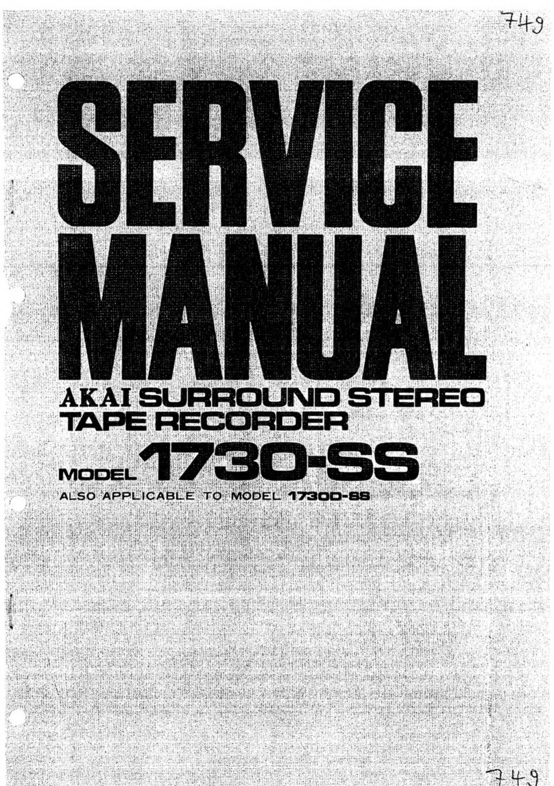
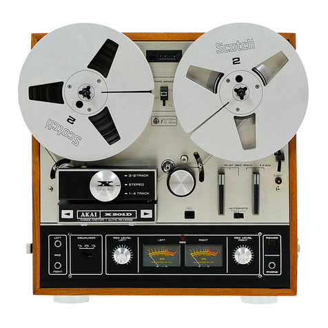
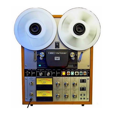
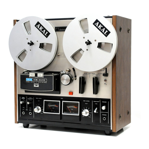
Akai 1730-SS User manual

1730-535
OPERATOR’S
MANUAL
~<a
SURROUND
STEREO
TAPE
RECORDER
Bb
©
©
ww
As
A
\<
yN
I.
AKAI.
MANUFACTURED
&
DISTRIBUTED
BY
AKAI
ELECTRIC
CO.,
LTD./AKAI
TRADING
CO.,
LTD.

TABLE
OF
CONTENTS
I.
GENERAL
INFORMATION
l-
Specifications
2-
Controls
........
Front
Panel
Controls
Back
Panel
Controls
3-
4-Channel
Stereo
Syestem
4-Channel
Stereo
Akai
Surround
Stereo
....
1.
OPERATING
INSTRUCTIONS
1-
4-Track
Recording/Playback
System
2—
Tape
Loading
3-
Voltage
and
Cycle
Conversion
4-
Tape
Speed
Selection
5-
Pause
Control..........
6-
Automatic
Shut-Off
....
7-
Fast
Forward
and
Rewind
Playback
..
Stereo
Playback
4-Channel
Surround
Stereo
Playback
2-Channel
Stereo
Playback
Playback
Using
Stereo
Headphones
9-
Recording
4-Channel
Surround
Stereo
Recording
Conventional
2-channel
Stereo
Recording
......:.ccsssssccscesseeseeeseesessnereseuueesseseees
12
Recording
from
Other
External
Sources
....
4-Channel
Surround
Stereo
Recording
..
2-Channel
Stereo
Recording
...
Dinh
JRCKS
iiaxsuscuansver
caus
Monitoring
........
10-
‘Tape
Splicing
and
Editing
.........
I]-
Head
Cleaning
«01...
12~
Head
Demagnetizing
13-
Tape
Erasing
14-
Trouble-Shooting
Chart
F
15%
“Lubrication
iicccessvevoosasvescariacssasanvrsenreacsenevass
sasueovingsos
dasshedausnvacanenesssnsveouneseonaniate
ll.
ACCESSORIES
l-
Standard
Accessories.
2-
Optional
Accessories

|.
GENERAL
INFORMATION
1-
SPECIFICATIONS
Track
System.
cco
sevsssesss-cseacies
4-track
4-channel/2-channel
compatible
stereo
Max.
Reel
Size
...........00....00.05
iad
Tape
Sp66d
apace
ertiscsicieceunes
7-1/2
&
3-3/4
ips
(+1%)
Wow/Flutter
...............:eceeeeee
0.12%
RMS
at
7-1/2ips
0.15%
RMS
at
3-3/4
ips
Frequency
Response.................,
30Hz
to
22,000Hz
(+3dB
at
7-1/2ips);
30Hz
to
15,000Hz
(+3dB
at
3-3/4
ips)
S/N
Ratio
Better
than
50dB
Distortion
Less
than
1.59%
(7-1/2
ips)
(1,000
Hz
“0°
VU
recording)
Erase
Ratio...........-.seccesssssesseee
Better
than
70dB
Equalization:
j.cicsciiccvcrensiesiedsees
Correct
equalization
for
playback
of
tapes
recorded
to
NAB
curve
Recording
Bias
Frequency
.........
100
kHz
Recording
Level
Indicator...
.
2
twin
type
VU
meters
RGRBS
ca
vxcansecvesnvegnr
essere
ines
Two
4-track
4-channel
stereo
heads
for
recording
and
playback.
Two
erase
heads
(2-track
&
full
track)
Fast
Forward
&
Rewind
Time...
75
seconds
at
60
Hz
(1,200
ft.
tape);
90
seconds
at
50
Hz
(1,200ft.
tape)
Output
Jacks
..,.........0...0...000-
4
Line
Output
Jacks
Output
Level:
1.23
V
Max.
Load
Impedance:
more
than
20k2;
2
Headphone
Jacks
(I
ea.
front/rear),
82
,
2
Speaker
Jacks,
82
Input
Jacke:
ccsccmopssssiiewmsverdsns
4
Mic
Input
Jacks:
0.4mV/30k2
4
Line
Input
Jacks:
40mV/100k2
DIN
Jake
3s
ssceconnaccospisvesiicoasnis
2
Output/Input
DIN
Jacks:
04V/5mV
Recording
Capacity
..................
4-channel
stereo
(30
min,
at
7-!/2ips
using
a
1,200
ft.
tape)
2-channel
stereo
(I
hr,
at
7-1/2ips
using
a
1,200
ft.
tape:
BE
BOOE
sacs
sncsestdesveaeaseoavencnxinaics
Hysteresis
synchronous
2-speed
motor
Music
Power
...,....ccccsesssssssesiess
20
W
(10
W
each
channel)
Undistorted
Power
..................
14
W
(7
W
each
channel)
Semi-Conductors
..............-..5065
19
Transistors
10
Diodes
Integrated
Circuits
..................
8
Linear
IC,
2
Power
IC
Speakers............ccsrceeseessersesseees
Two
4"
built-in
Speakers
Power
Supply..
..-
AC
100
to
240V
,
50/60
Hz
Pewer
Consumption..
..
75
W
Dimensions...................0:00secee
420(W)
x
450(H)
x
240,D)
mm
(16-1/2"
x
18"
x
9-1/2")
Sd
17
kg
(37-1/2
Ibs,

2.
CONTROLS
RESET
BUTTON
SUPPLY
REEL
TABLE
REEL
RETAINER
Built-In
Reel
Retainer
locks
reel
firmly
into
place.
CYCLE
CONVERSION
SWITCH
(A)
“Out
position,
50
[fz
;
in”
position.
60
Hz.
PINCH
WHEEL
Presses
against
capstan
to
transport
tape.
CAPSTAN
“Transports
tape.
HEAD
COVER
Houses
(trom
left
to
right)
Full
Track
Rrase,
2eTrack
Erase,
Recording,
and
Playback
Heads,
HEADPHONE
JACK
(Front
Channel)
For
use
in
monitoring
front
channel,
Use
Stereo
Headphones
of
82
impedance.
SPEAKER
Built-In
4”
front
channel
speaker
(for
2-channel
operation)
HEADPHONE
JACK
(Rear
Channel)
For
use
in
monitoring
rear
channel.
Use
Stereo
Meadpluones
of
8Q
impedance.
RECORD
SAFETY
BUTTON
=
|
p
SER
SR
]
SURROUND
STEREO
RECORDING
LEVEL
CONTROL
(Right
Front
Channel)
For
adjusting recording
input
level
of
right
front
channel.
Adjust
while
observing
right
front
VU
Meter,
RECORDING
LEVEL
CONTROL
|
—
:
==
(Left
Front
Channel)
For
adjusting
recording
input
level
of
left
front
channel.
Adjust
while
observing
left
front
VU
Meter.
TAPE
SPEED
SELECTOR
MICROPHONE
JACK
(Right
Front
Channel)
For
right
front
channel
recording.
MICROPHONE
JACK
(Left
Front
Channel)
For
left
front
channel
recording.
MONITOR
SWITCHES
‘To
monitor
program
source,
depress
SOURCE
Switch.
To
monitor
recorded
signals
or
for
playback,
depress
‘TAPE
Switch.
VU
METER
(Left
Front
Channel)
‘This
meter
indicates
left
rear
channel
recording
and
playback
level.
VU
METER
(Left
Rear
Channel)
This
meter
indicates
left
front
channel
recording
and
playback
level.
VU
METER
(Right
Rear
Channel)
‘This
meter
indicates
right
rear
channel
recording
and
playback
level,

Fig.
1
INDEX
COUNTER
Por
use
in
locating
positions
on
atape.
With
Reser
Bution,
art
Index
Counter
to
“MEME
before
beginning
recording
or
playback,
AUTOMATIC
SHUT-OFF
LEVER
Fer
Automatic
Shut-Oif,
thread
the
tape
through
the
Autos
matic
Shut-OWP
Lever
and
ser
the
Automatic
Shut-Off
Switch
to
“ON
position,
When
tape
comes
to
the
end
or
iy
broken,
the
power
of
the
entire
unit
is
cus
aff
\
convenient
safery
feature
if
the
recorder
is
left
unattended.
PLAY;RECORD
LEVER
For
PLAYBACK
mode,
set
PLAY
ty
position.
Dor
RECORD.
ING
mode,
depres
RECORDING
SALTETY
BUPTON
ard
while
holding
at
depressed
position,
ser
PLAYBACK
RLC
LIVER
te
REC
position,
REEL
RETAINER
Built-In
Reel
Retainer
locks
reel
firmly
into
place.
TAKE-UP
REEL
TABLE
SPEAKER
Buik-In
4"
front
channel
speaker
(for
2-channel
operation)
REWIND/FAST
FORWARD
LEVER
Vor
effecting
Kwd,
or
FL
Fwd
Mode.
Deo
not
attempt
to
operate
this
lever
until
Play/Record
Lever
is
returned
to
neutral
position
(or
vice-versa).
PAUSE
LEVER
Convenient
for
use
in
temporarily
suspending
tape
movement
during
recording
wr
playback
operation,
To
release,
Lift
slightly
upward
and
ther
yeturn
to
normal
(lower)
pxosition,
AUTOMATIC
SHUT-OFF
SWITCH
‘This
switeh
is
linked
to
the
Automatic
Shut-OiT
Lever.
If
ar
“ON
position,
when
tape
comes
to
end
or
is
broken,
the
power
of
entire
unit
is
cut.
A
convenient
safety
feature
if
recorder
is
left
unattended.
POWER
SWITCII
RECORDING
LEVEL
CONTROL
‘Left
Rear
Channel)
Vor
adjusting
recording
input
level
of
left
rear
channel.
Adjust
while
observing
left
rear
VU
Meter.
SPEAKER
VOLUME
CONTROL
For
speaker
volume
control.
Clockwise
increases
volume.
MICROPHONE
JACK
(Right
Rear
Channel)
Por
right
rear
channel
recording.
MICROPHONE
JACK
(Left
Rear
Channel)
Yor
left
rear
channel
recording.
STEREO
SELECTOR
For
2-channel
Stereo
operation
depress
“2
CH”
bution
and
for
4-channel
Stereo
operation
depress
“4
CHU’
button,
RECORDING
LEVEL
CONTROL
(Right
Rear
Channel}
Vor
adjusting
recording
input
level
of
right
rear
channel,
Adjust
while
observing
right
rear
VU
Meter,
VU
METER
(Right
Front
Channel)
‘This
meter
indicates
dght
front
channel
recording
and
play-
back
level.

SPEAKER
SWITCH
Maute,'Normal
Speaker
Switch
SPEAKER
JACKS
(Left.
Right)
Jacks
for
connection
of
external
speakers.
DIN
JACK
(Rear
Channel)
Enables
inter-connection
with
external
stereo
amplifier
by
use
of
a
single
DIN
connection
cord
(DR-I11
connection
cord
standard
accessory),
LINE
OUTPUT
JACK
(Right
Rear
Channel)
For
playback,
connect
to
Tape
Input
Jark
(right)
of
external
amplifier.
LINE
INPUT
JACK
(Right
Rear
Channel)
For
rceording,
connect
to
Output
[ack
Crghe)
of
external
recording
source,
FUSE
POST
VOLTAGE
SELECTOR
PLUG
In
case
of
necessity
to
change
voltage
input,
remove
fuse
post
&
plug
and
set
plug
to
proper
voltage,
AC
CORD
CYCLE
CONVERSION
SWITCH
(B)
This
switch
and
Cyele
Gonversion
Switch
(A)
on
front
panel
must
be
sct
in
accordance
with
area
power
source.
Set
both
switches
to
50
of
60)
Hz
as
required,
LINE
OUTPUT
JACK
(Left
Rear
Channel}
For
playback,
connect
to
Tape
Input
Jack
(left)
of
external
amplifier,
LINE
INPUT
JACK
(Left
Rear
Channel)
For
recording,
connect
to
Output
Jack
(left)
of
external
recording
source,
LINE
OUTPUT
JACK
(Right
Front
Channel)
For
playback,
connect
to
‘l'ape
Input
Jack
(right)
of
external
amplifier,
LINE
INPUT
JACK
(Right
Front
Channel)
For
recording,
connect
to
Ourpat
Jack
Cright)
of
external
recording
source.
DIN
JACK
(lront
Channel)
Hnables
inter-connection
with
external
amplifier
by
use
of
a
siagle
DIN
connection
cord
(D-IL
connection
cord
standard
accessory).
173055
ate
ea
LINE
OUTPUT
JACK
(Left
Front
Channel)
For
playback,
connect
to
Tape
Input
Jack
(left)
of
external
amplifier,
LINE
INPUT
JACK
(Lett
Front
Channel)
For
recording,
connect
to
Output
jack
Cleft}
of
external
recording
source.

3-4-CHANNEL
STEREO
SYSTEM
@
4-CHANNEL
STEREO
In
the
continued
pursuance
of
more
aesthetical
sound,
another
stereo
revolution
has
taken
place...
A
new
stereo
“break-through”
from
2-channel
to
4-channel
stereo,
This
“move-up”
to
4-channel
stereo
is
cqually
as
great
an
achievement
as
the
advancement
from
monaural
to
2-channel
stereo.
Just
as
2-channel
stereo
sound
reproduction
meant
the
exodus
of
flat
monaural
sound,
this
epoch-
making
new
system
climinates
the
inability
to
pick
up
and
reproduce
pure
concert
hall
sound,
New
4-channel
stereo
uses
4
signal
paths
or
sound
tracks
in
the
program
material
and
in
playback
approximates
the
complexity
of
the
sound
waves
which
reach
the
listener's
ear
when
attending
a
live
concert
hall
performance,
For
playback,
4
speakers
are
positioned
to
surround
the
listener.
The
sound
from
the
front
and
rear
speakers
give
the
listener
an
exciting
“sense
of
presence”,
With
the
4
speakers
each
delivering
separate
sound,
left
&
right
in
front
and
left
&
right
in
back
of
you,
you
are
literally
surrounded
with
a
wall
of
sound
which
fills
the
“hole
in
the
middle”.
This4-dimensional
musical
reproduction
makes
conventional
2-channel
stereo
seem
empty
and
insufficient.
@
AKAI
“SURROUND
STEREO”
Exhibitions
of
AKAL's
4-channe!
stereo
system
are
already
being
held
in
various
parts
of
the
world
and
are
being
termed
by
the
listeners
as
“SEN
IONAL™,
AKAL's
surround
stereo
supplements
conventional
sterco’s
2)
front
speakers
with
2
additional
rear
speakers
to
form
the
“2-2
System”,
The
listener
is
surrounded
by
two
sets
of
speakers
(left
&
right
front
and
Jeft
&
right
rear),
This
arrangement
does
not
mean,
however,
that
simply
adding
vo
speakers
to
a
2-channel
system
is
all
that
is
necessary
for
4-channel
playback.
At
recording
time,
4
microphones
are
used
and
sound
is
picked
up
from
4
separate
places.
Four
separate
recordings
are
made
using
4
separate
channels
‘all
four
tracks
in
one
direction),
This
4-channel
stereo
tape
feeds
into
4
preamplifiers
and
+
main
amplifiers
to
activate
a
4-speaker
system,
‘Thus,
at
playback
time,
sounds
from
separate
channels
are
emitted
from
cach
speaker,
providing
the
listener
with
a
feeling
that
he
is
listening
to
concert
hall
music
from
the
best
seat
in
the
auditorium,
If
you
are
a
jazz
fan,
for
instance,
you
can
record
and
position
the
speakers
for
playback
so
that
the
spine-tingling
sa
ted
from
the
left
front
speaker,
drums
from
right
front,
piano
from
left
rear,
and
bass
from
right
rear.
This
arrangement
gives
the
listener
1“
sounds
are
emit-
areal
here
in
which
you
have
the
feeling
of
being
exactly
in
the
middle
of
the
live
performance.
sense
of
presence”
creating
an
atmosp-

I].
OPERATING
INSTRUCTIONS
1-4-TRACK
RECORDING/
PLAYBACK
SYSTEM
The
AKAL
1730-SS
employs
a
4-track
system
which
can
be
used
for
either
4-channe!
or
2-
channel
stereo
recording/playback.
Tracks
are
selected
by
operating
the
STEREO
TRACK
SELECTOR
Switches.
M4-CHANNEL
STEREO
RECORD-
ING;PLAYBACK
4-channel
stereo
recording/playback
requires
the
simultaneous
use
of
all
+
tracks
in
one
direc-
tion.
Set
Stereo
Selector
to
“4-CH"
(See
page
3),
@
2-CHANNEL
STEREO
RECORD-
ING/PLAYBACK
2-channel
stereo
recording/playback
requires
the
simultaneous
use
of
two
tracks.
Set
Stereo
Selector
to
“2-CII”
and
use
front
channel
cont-
rols.
The
first
stereo
recording/playback
takes
place
on
tracks
|
and
3,
and
the
second
on
tracks
2
and
4
after
the
reels
have
been
inverted.
2-TAPE
LOADING
Place
a
full
reel
of
tape
on
SUPPLY
REEL
TABLE
and
an
empty
reel
on
the
TAKE-UP
REEL
TABLE.
Thread
the
tape
as
illustrated
by
the
dotted
line
in
Fig,
3.
Lock
reels
into
place
with
REEL
RETAINERS
provided
on
reel
shafts.
IMPORTANT
:
Be
sure
to
thread
tape
through
AUTOMATIC
SHUT-OFF
LEVER.
4-track
4-channel
stereo
tape
1
—
Front
Left
CH
2
Sarat
<a
Rear
Left
CH
3
oe
Front
Right
CH
4
_—_——
Rear
Right
CH
1
—_—_
Left
CH
2
—_—
Right
CH
3
_—_
Right
CH
4
——
Left
CH
—>
Side
A
+
Side
B
4-track
2-channel
stereo
tape
ee
,
Gee

3-VOLTAGE
AND
CYCLE
CON-
VERSION
@
VOLTAGE
Model
1730-SS
is
operable
anywhere
in
the
world,
With
the
built-in
step-down
power
trans-
former,
the
operator
can
easily
readjust
the
recorder
to
any
one
of
the
six
stages
of
power
voltage
from
100
to
240
volts
A.C,
The
operator
is
requested
to
check
the
previously
set
voltage
before
operation.
If
another
voltage
ts
required,
readjustment
can
be
made
as
follows:
il)
Remove
the
FUSE
POST
as
shown
in
Fig,
A.
Remove
VOLTAGE
SELECTOR
PLUG
and
reinsert
to
standard
area
voltage.
2;
The
VOLTAGE
SELECTOR
as
shown
in
Figs.
B,C.
and
Dis
a
rotable
plug-in
type
offering
6
selections
/100/110/120/200/220/
240),
3,
Change
the
fuse
according
to
voltage,
7
=e
Velie
TOOW
te
120
200V
ww
OV
|
|
Le
aaa
|
CAUTION:
Disconnect
power
plug
from
AC
outlet
before
readjusting
voltage,
To
maintain
optimum
performance
and
prolong
the
life
of
your
machine,
it
is
important
that
the
line
voltage
be
held
within
10
percent
deviation
of
standard
voltage,
@
CYCLES
Correct
tape
speed
cannot
be
obtained
if
the
‘
CYCLE
CONVERSION
SWITCHES
are not
OWT
50Hz
OUT
SOHz
properly
positioned.
CYCLE
CONVERSION
~~
SWITCH
(A)
is
located
on
the
upper
center
of
the
face
panel
and
(B)
ts
located
at
the
rear
of
the
recorder.
Using
a
screw
driver,
rotate
CYCI.E
CONVERSION
SWITCH
(A)
coun-
ter-clockwise
approximately
one-cighth
—
of
IN
6OHz
:
;
IN
6OHz
aturn.
The
switch
can
then
be
moved
cither
OUT
or
IN.
50
cycle
operation
is
obtained
by
moving
the
switch
OUT
(Fig.
A-1)
and
60
cycle
operation,
by
moving
the
switch
IN
(Fig.
A-2).
The
switch
should
be
rotated
back
to
its
original
position
after
it
has
been
moved
co
either
IN
or
OUT
|
position.
CYCLE
CONVERSION
SWITCH
(B)
must
also
be
reset
accordingly,
CAUTION:
Do
not
attempt
to
rotate
the
CYCLE
CONVERSION
SWITCHES
when
the
motor
is
not
running.

4-TAPE
SPEED
SELECTION
he
4
-)
ej)
J)
The
1730-SS
Surround
Stereo
Tape
Recorder
operates
on
two
tape
speeds
(3-3/4
and
7-1/2
ips).
For
quick
and
easy
tape
speed
selection,
operate
convenient
TAPE
SPEED
SELECTOR,
334
RECORDING
TIME
TAPE
SPEED
L
Tape
4-Track 4-Track
Length
4-Channel
2-Channel
T
—
los
em/sec.|
19
cm/sec,
|
9.5
em/sec.|
19
cm/sec.
(3-3/4
ips)
|
(7-1/2
ips)
|
{3-3/4
ips)
|
(7-1/2
ips)
1,200
ft.|
I
hour
0.5
2
i
1,800
ft.
15
0.75
3
1.5
2,400
ft.
2
2
Bee
eS
Fig.
6
5-PAUSE
CONTROL
To
momentarily
stop
the
tape
during
recording
playback,
set
the
PAUSE
LEVER
to
“Pause”
position
(as
shown
in
Fig.
7).
PAUSE
CONT-
ROL
will
not
function
during
fast
forward
or
rewind
operation,
PAUSE
CONTROL
is
useful
in
editing
the
tape
during
recording
(lift
lever
to
stop
record-
ing
when
a
certain
portion
of
the
program
is
not
desired).
Note
that
when
the
lever
is
releas-
ed
and
recording
again
commences,
no
annoy-
ing
“click”
is
impressed
on
the
tape.
7-FAST
FORWARD
AND
REWIND
Fast
Forward
or
Rewind
is
performed
by
operating
FAST
FORWARD/REWIND
LE-
VER.
Fast
Forward
or
Rewind
permits
rapid
selections
of
recordings
on
the
tape.
The
Fast
Forward/Rewind
Lever
is
automatically
locked
into
position
and
cannot
be
operated
while
PLAYBACK
LEVER
is
in
operation
and
vice-versa.
6-AUTOMATIC
SHUT-OFF
One
of
the
exclusive
features
of
Model
1730-SS
is
the
function
of
the
automatic
shut-off
unit.
If
the
AUTOMATIC
SHUT-OFF
SWITCH
is
set
to
“ON”
position,
when
the
tape
comes
to
the
end
or
is
accidentally
broken,
the
AUTO-
MATIC
SIIUT-OFF
LEVER
drops,
cutting
off
the
power
of
the
entire
unit.
Aer
,
|
Rec
|
ww
—
=
Fig.
9

8-PLAYBACK
*
(TACE
OME»
Hy
2
REAR
REC
LEVEL
——VvoLuraR,
Geel
clooe
B
STEREO
PLAYBACK
Please
be
sure
to
check
the
following
prior
to
RIGHT
&
LEFT
.
operation,
@
*
Heads
are
clean
and
free
of
dust.
*
As
tape
which
has
not
been
used
for
a
RECIPE
tats
ee
period
of
time
may
have
become
sticky,
run
LINE
INPUT
tape
once
before
using.
*
Tape
is
loaded
properly.
Fig.
11

@
4-CHANNEL
SURROUND
STEREO
PLAYBACK
FRC
AT
CWE
Foe
Mure.
{ffi
Norma
Richt
#5
Ae
Ag)
£9)
EX
ERNAL
5)
EAKERS
~
REC
/P
a
LINE
INPUT
—
Model
1730-SS
is
equipped
with
a
builtin
2-channel
power
amplifier.
Therefore,
a
2-channel
external
amolifier
and,
an
extra
pair
of
speakers
are
all
that
is
necessary
for
4-channel
surround
stereo
playback.
If
a
2-channel
stereo
amplifier
is
used,
connect
FRONT
CHANNEL
LINE
OUTPUT
JACKS
to
TAPE.
INPUT
JACKS
of
external
amplifier.
Connect
a
pair
of
rear
speakers
to
the
Speaker
Terminals
of
Model
1730-SS
and
another
pair
of
front
speakers
to
the
external
@
2-CHANNEL
STEREO
PLAYBACK
Connect
power
plug
and
load
a
2-channel
stereo
pre-recorded
tape.
@
Turn
on
POWER
SWITCH,
@®
Depress
2-GH
STEREO
SELECTOR.
@©
Select
Tape
Speed.
@
Set
Speaker
Switch
to
NORM.
@®
Depress
TAPE
MONITOR
SWITCH.
@®
Set
PLAYBACK/REC
LEVER
to
PLAY
and
adjust
SPEAKER
VOLUME
CONT-
ROL.
@
Invert
reels
for
playback
on
tracks
2-4.
Note:
The
2-channel
internal
power
amplifier
of
Model
1730-SS
automatically
switches
to
rear
channel
operation
when
the
4-Channel
Stereo
Selector
is
depressed,
and
to
front
channel
operation
when
the
2-Channel
Stereo
Selector
is
depressed.
Cerr
REC/P.B.
LINE
INPUT
amplifier.
(Refer
to
Fig:
12).
If
wvo
2-channel
stereo
amplifiers
are
used,
connect
REAR
&
FRONT
CHANNEL
LINE
OUTPUT
JACKS
respectively
to
TAPE
INPUT
JACKS
of
both
external
amplifiers.
Connect
a
pair
of
speakers
to
the
Speaker
Terminals
of
both
external
amplifiers,
and
set
speaker
switch
of
Model
1730-SS
to
MUTE
position
Connect
power
plug
and
load
a
4-channel
sterco
pre-recorded
tape.
M
TE
NOF
MAL
te
ric
it
2
.
©)
(e)
EXTERNAL.
SPEAKERS
Sere)
eit
fe
ES,
leevocvese
Fig,
12
&®
Turn
on
POWER
SWITCH.
;
(B
Depress
4-Cl1
SELECTOR
SWITCH.
@
Select
Tape
Speed.
©
Set
Speaker
Switch
to
NORM.
(®
Depress
TAPE
MONITOR
SWITCH.
®
Set
PLAYBACK/REC
LEVER
to
PLAY
and
adjust
speaker
Volume
Control
of
Model
1730-SS
and
Speaker
Volume
Con-
trols,
etc.
of
external
amplifier.
rxx
Ney
O00
OG:

9-RECORDING
Please
be
sure
to
check
the
following
prior
to
operation
:
*
Heads
are
clean
and
free
of
dust.
*
Heads
are
demagnetized,
*
Use
good
quality
tape
(new
tape
gives
best
results).
*
As
tape
which
has
not
been
used
for
a
period
of
time
may
have
become
sticky,
run
once
before
using.
*
Tape
is
loaded
properly.
@
PLAYBACK
USING
STEREO
HEADPHONES
Two
separate
front
and
rear
channel
Stereo
Headphone
Jacks
are
provided
for
your
convenience,
In
case
of
2-channel
playback,
use
front
channel
Headphone
Jack
only.
For
private
listening,
use
Stereo
Headphones
of
low
impedance
type
(82).
AKAL
Model
ASE-22
is
highly
recommended.
MOOBOOO
Es

F<
FN,
BACK
GROUND
MUSIC
B
4-CHANNEL
SURROUND
STEREO
RECORDING
Connect
power
cord
and
load
a
tape.
@
Turn
on
POWER
SWITCH.
®
Depress
4+-CH
STEREO
SELECTOR.
©
Select
Tape
Speed.
@®
With
RESET
BUTTON,
set
INDEX
COUNTER
to
“OOOO”.
This
Index
Counter
provides
an
easy
reference
for
locating
positions
on
the
tape,
©
Insert
microphone
plugs
into
MICRO-
PHONE
JACKS
(front
left
&
right
and
rear
left
&
right).
#)
Depress
SOURCE
MONITOR
SWITCH.
@
Set
PAUSE
LEVER
to
PAUSE
position,
@
While
depressing
RECORDING
SAFETY
BUTTON,
set
PLAYBACK/REC
LEVER
to
REC.
}
Adjust
and
balance
microphone
volume
levels
by
operating
corresponding
REC
LEVEL
CONTROLS
while
observing
corresponding
VU
Meters.
Normal
record-
ing
should
not
exceed
“O"
VU
on
any
of
the
respective
VU
Meters.
J)
When
an
optimum
recording
level
has
been
determined,
release
PAUSE
LEVER
to
begin
recording.
®
‘To
stop
recording,
return
PLAYBACK/
REC
LEVER
to
STOP
(vertical)
position.
1)
In
case
of
using
headphones
for
monitoring
recorded
signals,
depress
TAPE
MONITOR
SWITCH,
CONVENTIONAL
2-CHANNEL
STEREO
RECORDING
For
conventional
2-channel
stereo
recording
substitute
the
following
steps
for
steps
®
&
of
4-channel
stereo
recording
procedure
and
add
step
QD.
@®
Depress
2-CH
STEREO
SELECTOR.
Insert’
microphone
plugs
into
MICRO-
PHONE
JACKS
(front
left
&
right),
Maintain
a
distance
of
at
least
2
meters
(7
ft.)
between
microphones.
@
Invert
reels
for
recording
on
tracks
2-4,
There
are
many
possibilities
for
microphone
placement.
Experiment
with
a
variety
of
positions
according
to
your
own
niusical
taste.
Fig.
17

H
RECORDING
FROM
OTHER
EXTERNAL
SOURCES
From
another
tape
recorder
For
4-channel
Surround
Stereo
recording,
connect
the
front
and
rear
LINE
OUTPUT
JACKS
of
the
playback
recorder
to
the
front
and
rear
LINE
INPUT
JACKS
of
Model
1730-SS
instead
of
Step
@
of
4-channel
surround
stereo
recording
procedure,
PLAY
BACK
MACHINE
RECORDING
MACHINE
Fig.
20
B
4-CHANNEL
SURROUND
STEREO
RECORDING
For
4-channel
stereo
recording,
connect
the
front
&
rear
channel
LINE
INPUTS
of
Model
1730-SS
to
the
front
&
rear
channel
OUTPUTS
of
your
4-channel
external
source
instead
of
step
©
of
4-channel
stereo
recording
procedure.
RONT
ies
CINE
OUTPUT
RIGHT
REC./P.B,
LEFT
Ll
eece
LINE
INPUT
ied
Fig.
18
REC./P.B.
LE
=
LINE
INPUT
ee
|
Fig.
19
For
2-channel
recording,
connect
the
LINE
OUTPUT
JACKS
of
the
playback
machine
to
the
front
channel
LINE
INPUT
JACKS
of
Model
1730-SS
instead
of
Step
©
of
conven-
tional
2-channel
stereo
recording
procedure,
PLAYBACK
MACHINE
RECORDING
MACHINE
Fig.
21
@
2-CHANNEL
STEREO
RECORDING
From
an
external
amplifier
(fig.
18)
Connect
the
OUTPUT
leads
of
the
external
amplifier
or
tuner
amplifier
to
the
front
channel
LINE
INPUT
JACKS
instead
of
Step
65
of
con-
ventional
2-channel
sterco
recording
procedure.
From
a
record
player
(fig.
19)
A
“crystal
pick-up”
or
a
“ceramic
pick-up”
can
be
connected
directly
to
the
front
channel
LINE
INPUT
JACKS
instead
of
Step
@
of
conventional
2-channel
stereo
recording
proce-
dure.
If
a
“magnetic
cartridge”
is
used,
for
proper
equalization,
it
must
be
connected
to
the
Line
Input
Jacks
through
an
external
amplifier.

REC/FB.
Left
RIGHT
REC/PO.
LEFT
{
EXTERNAL
SPEAKERS
1
LINE
INPUT
————
tine
eur
———!
Fig.
22
@
DIN
JACKS
The
DIN
JACKS
at
the
rear
of
the
recorder
are
for
use
in
inter-connecting
Model
1730-SS
with
an
external
stereo
amplifier.
This
system
enables
easy
recording
and
playback
through
an
external
amplifier
as
the
complex
connec-
tion
or
disconnection
of
several
separate
plugs
is
not
necessary.
An
AKAI
DR-!11
DIN
Connection
Cord
has
been
included
in
the
standard
accessories
for
your
convenience,
HB
MONITORING
For
monitoring,
connect
Stereo
Headphones
to
Front
or
Rear
STEREO
HEADPHONE
JACK.
Stereo
Headphones
should
be
of
82
impedance
type,
ARAL
Model
ASE-22
is
highly
recommended,
10-TAPE
SPLICING
AND
EDITING
Cut
tape
diagonally
with
an
overlap
so
that
the
ends
are
lined
up
(cutting
tape
on
diagonal
eliminates
detection
of
the
splice
in
recording).
Cover
aligned
ends
with
SPLICING
TAPE.
Press
firmly,
exerting
pressure
to
secure
ends
evenly,
Trim
off
excess
splicing
tape
(Cut
into
recording
tape very
slightly
as
illustrated
by
dotted
lines.
This
eliminates
the
possibility
of
a
sticky
splice).
Splicing
of
tape
using
scissors
requires
skillful
work.
With
our
specially
designed
PORTABLE
SPLICER,
splicing
can
be
done
very
smoothly.

11-HEAD
CLEANING
Tape
Oxide/Dust
Deposits
Cause
90%
of
Tape
Recording
Failures
For
quality
performance
it
is
imperative
that
tape
recorder
heads
be
kept
clean
at all
times.
Dust
and
magnetic
particles
from
the
tape
tend
to
deposit
on
the
heads
after
prolonged
use
of
the
recorder.
This
results
in
poor
head-
to-tape
contact
deteriorating
sound
quality
and
sensitivity.
Such
dust
causes
drastic
drops
in
recording/playback
levels
and
nullifies
high
quality
sound,
Make
it
a
rule
to
clean
the
heads
every
time
your
use
your
recorder,
AKAT's
Head
Cleaning
Kit
Model
HC-500
is
recommended
for
remov-
ing
foreign
matter
deposited
on
the
heads.
Note:
Set
Playback/Rec
Lever
to
PLAY
position
while
cleaning
the
heads.
EXAMPLE
CLEAN
HEAD
Frequency
response
curve

12-HEAD
DEMAGNETIZING
Normally
the
steel
pole
pieces
which
form
a
part
of
the
Recording
and
Playback
Heads
become
slightly
magnetized,
The
effect
of
slight
head
magnetization
is
that
it
partially
erases
the
tape,
especially
at
high
frequencies,
Generally,
this
condition
can
be
detected
by
the
loss
of
high
frequency
response
which
can-
not
be
corrected
through
head
alignment,
d
by
using
magnetized
tools
in
the
vicinity
of
the
Severe
magnetization
(which
may
be
caus
heads)
will
result
in’
noise
or
considerable
distortion
in
addition
to
the
loss
of
high
frequen-
cy
response,
Although
Model
1730-SS
already
has
a
built-in
head
demagnetizing
circuit,
it
is
recommended
that
head
demagnetization
be
performed
periodically.
This
can
be
accomp-
lished
by
touching
the
head
lightly
with
the
demagnetizer
and
making
several
small
circular
motions
over
all
heads
surface
areas
as
well
as
the
head
housing.
NOTE:
To
avoid
scratching
the
bead
surface.
we
suggest
that
you
cover
both
prongs
of
the
head
demagnetizer
with
a
sort
of
masking
tape,
13-TAPE
ERASING
Any
signals
previously
recorded
on
the
tape
will
be
automatically
erased
as
a
new
record-
ing
is
made.
For
erasing
only,
load
tape
and
set
recorder
to
recording
mode.
Model
1730-
is
equipped
with
separate
2-channel
and
full
track
erase
heads,
For
full
track
erase,
set
STEREO
TAPE
SELECTOR
to
“4-CH”
position
and
for
2-Channel
erase,
set
to
“2-CH™
position.
No
plugs
should
be
connected
to
the
line
input
jacks
or
microphone
jacks.
For
quick
and
complete
erasing,
the
use
of
a
Bulk
Tape
Eraser
is
recommended,

14-TROUBLE
SHOOTING
CHART
The
conditions
listed
below
do
rot
indicate
mechanical
failure
of
your
unit.
If
your
machine
exhibits
any
of
these
conditions,
check
for
trouble
as
indicated.
Loss
of
sensitivity
and
tone
quality
-
Dirty
Erase
Head
This
prevents
pre-recorded
material
from
being
completely
erased.
-
Dust
adhering
to
Recording
Head
For
head
cleaning
instructions,
see
“HEAD
CLEANING”
procedure.
+
Magnetized
Head
For
demagnetizing
instructions,
see
“HEAD
DEMAGNETIZING”
procedure.
+
AC
Power
Voltage
lower
than
the
Voltage
to
which
your
machine
is
adjusted.
Irregularity
of
tape
transport
+
Grime
adhering
to
heads
+
Oil
on
capstan
+
Sticky
or
dirty
tape
surface
+
Bent
Take-Up
Reel
Will
not
record
-
Check
position
of
controls
and
plugs
of
both
Model
1730-SS
and
external
source
Notes:
|}.
Your
machine
requires
constant
voltage
for
optimum
performance.
2.
Ifthe
sound
sources
are
so
far
away
from
the
microphones
that
the
recording
level
controls
must
be
turned
up
to
maximum,
some
hum
or
noise
will
inevitably
be
recorded,
A
test
recording
is
recommended
before
attempting
a
final
recording.
3.
Should
there
be
any
problem
with
your
machine,
please
take
it
to
your
nearest
authorize
1
agent
or
inquire
at
our
Service
Dept.
in
Tokyo,
Japan.
15-LUBRICATION
Although
the
motor
of
Model
1730-SS
has
been
sufEciently
oiled
for
prolonged
usc,
for
maxi-
mum
service
and
optimum
performance,
take
your
machine
to
your
local
AKAI
Service
Agent
for
occasional
lubrication.

eo}
Ill.
ACCESSORIES
_
A
SH
1-STANDARD
ACCESSORIES
7"
4-channel
Stereo
Demonstration
Tape
............0::c0000000
1
7"
Empty
Reel
Connection
Cord
(DR-111)
sua
yaanlaatiphian
bi
ninsteRaay
Pave
MAE
1
Spare:
Biases
scopes
Gs
Boss
dav
coeeas
deacsastasecatoenietaeriones
2
Operator's:
Manuals
s..
tis
svesssvszeacesev
cs
carnscsshcxteeeorsnisccsecs
1
2-OPTIONAL
ACCESSORIES
READ
CLEANS
KAT
iad
STEREO
HEADPHONES
TAPE
SPLICER
AS-3
CONNECTION
CORDS
ASE-9S
ASE-20
(Uni-directional)
UM-101
>
ASE-22
DM-13
$C-180
RM-130
Other manuals for 1730-SS
1
Table of contents
Other Akai Tape Deck manuals