I.
I.
IV.
VI.
VIL.
Vil.
IX.
SECTION
I
SERVICE
MANUAL
TABLE
OF
CONTENTS
SPECIFICATIONS
.......c.ccsccsssecssseccsssecessscssesecssaeeeseseeersessessnseeeeennees
4
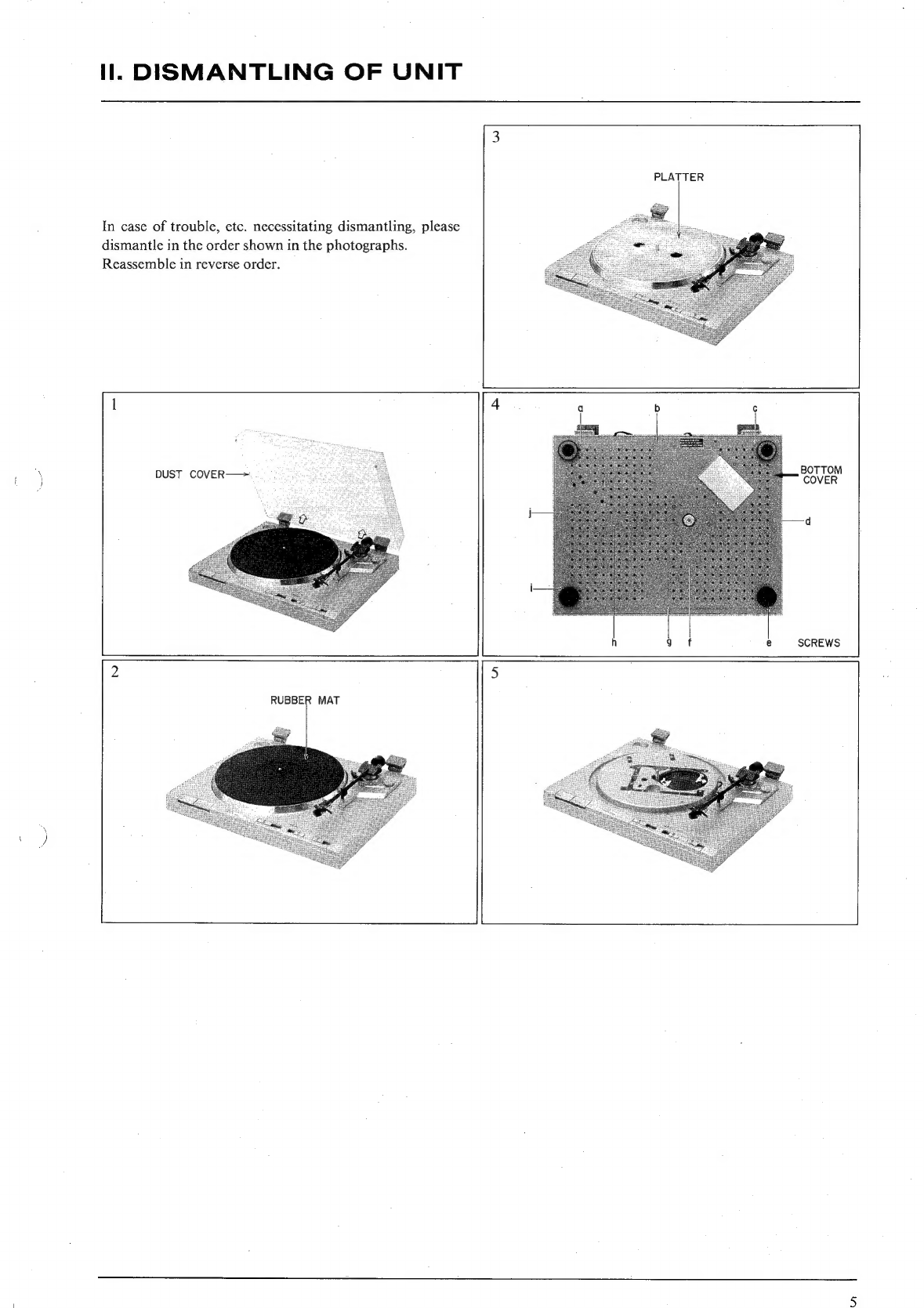
DISMANTLING
OF
UNIT
........ccceceeesecssscecccnscnereceeseeessrsereeseeeeeenes
5
CONTROLS
6
PRINCIPAL
PARTS
LOCATION
.,.....ccccssssssssssesssesssssseseeesecensenees
7
VOLTAGE
AND
CYCLE
CONVERSION
........cssssssssccssrseceeseeeeeseces
8
1.
VOLTAGE
CONVERSION..........ceeceee
obgastadetpindeassvistszacisceaneesee’
8
2.
CYCLE
CONVERSION
..........:cccseescossssssescscerceenssesenseents
seesesesenegens
8
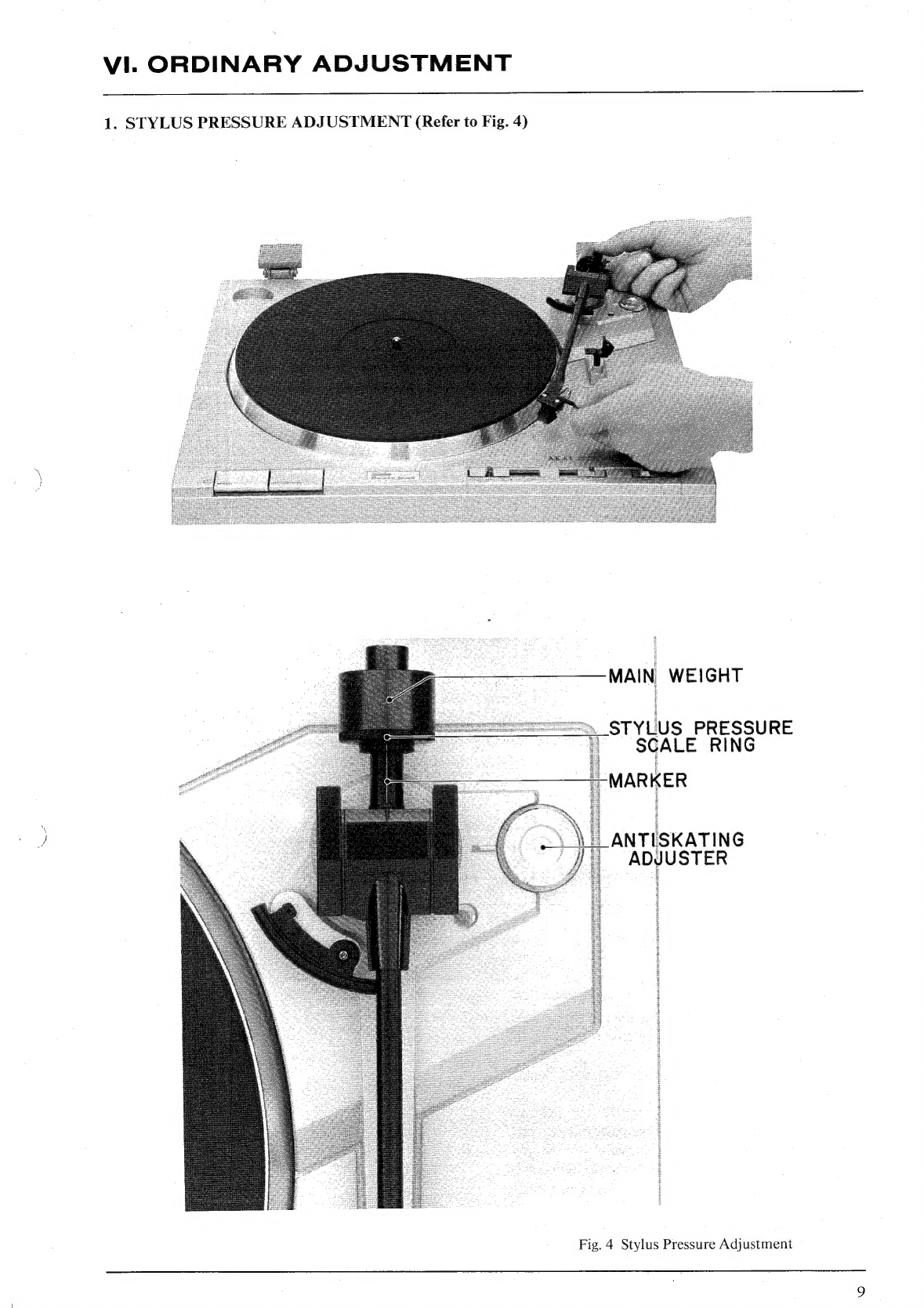
ORDINARY
ADJUSTRMENT
..........:ccsscccssssssreseccerssssreeeeessseneesens
9
1.
STYLUS
PRESSURE
ADJUSTMENT
....ccssesssessecsssesssietsesenees
rexede
9°
2.
OVERHANG
(Not
necessary
for
AP-Q310/€).....
ci
ceeiseesseniesceeeee
10°.
MECHANICAL
ADJUSTMENT.
........cssccsscccscssscesesescsereesessensesenees
11
1.
TONE
ARM
LIFTER
ADJUSTMENT
.....cccesssssessssstssssseesssssesssses
11
2.
TONE
ARM
BRAKE
ADJUSTMENT
.0.....eeeccceescceseteeeettseeeneeees
12
3.
-LEAD-IN/LEAD-OUT
ADJUSTMENT
0.0...
.cceeeeceeeesreeeeeeneeee
13
'
4,
RETURN
PLUNGER
POSITION
ADJUSTMENT...
13
ELECTRICAL
ADJUSTMENT
...........cssccsssssssccctecccsssserecseteeseeeeee
wee
14
1.
OFF-SET
VOLTAGE
ADJUSTMENT
(VR2,
3)
AND
TORQUE
DIFFERENCE
ADJUSTMENT
(VRI)......
eee
14
2.
WOW
AND
FLUTTER
CONFIRMATION
.........ceesseseesseeeeeeee
14
CLASSIFICATION
OF
VARIOUS
P.C
BOARDS
..........cessssccesseess
15
1.
P.C
BOARD
TITLES
AND
IDENTIFICATION
NUMBERS......
[Se
2.
COMPOSITION
OF
VARIOUS
P.C
BOARDS
oe
eeeeeceeeceeees
16
For
basic
adjustments,
measuring
methods,
and
operating
principles,
refer
to
GENERAL
TECHNICAL
MANUAL.