<2
RO
VII.
SECTION
1
SERVICE
MANUAL
TABLE
OF
CONTENTS
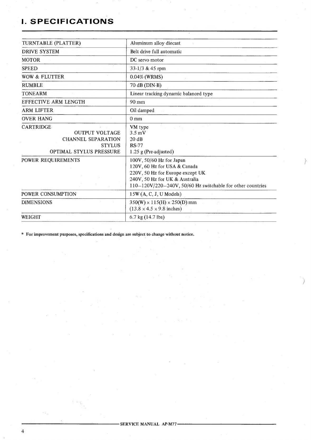
SPECIFICATIONS
.
0...
26
ice
ete
eet
e
nee
e
scene
4
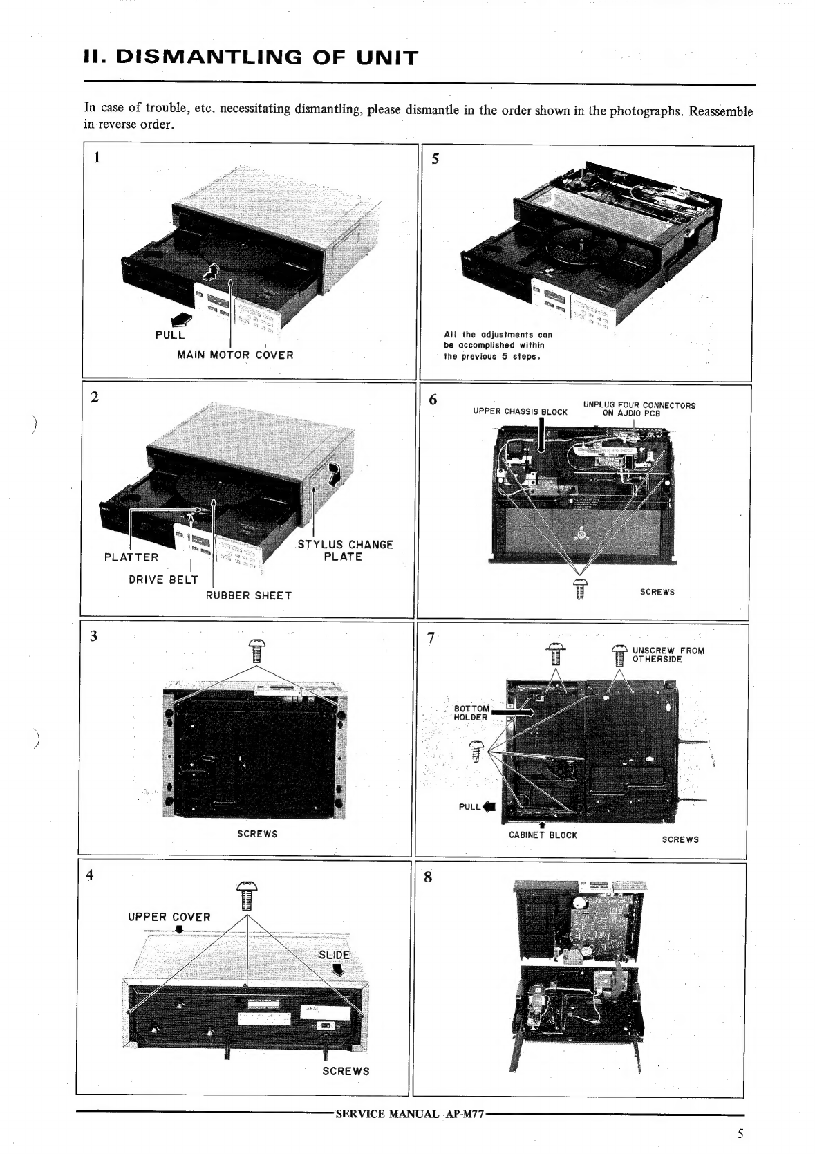
DISMANTLING
OF
UNIT
..
0.0.0...
0.
ccc
eee
eee
5
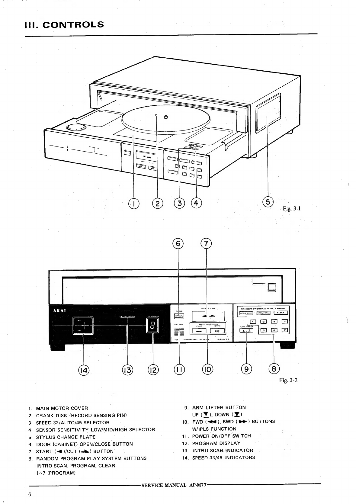
CONTROES
50555
esraiend
eh
ese
Sens
PS
aE
eh
ac
cca
nels
Geka
oR
Botan
6
PRINCIPAL
PARTS
LOCATION
..............
0.00000
cece
eens
7
DESCRIPTION
OF
MISCELLANEOUS
OPERATIONS
..............
9
5-1
OUTLINE
OF
AP-M77
FUNCTIONS................0000055
9
5-2
SPECIFICATION
OF
VARIOUS
KEY
OPERATIONS
...........
9
5-3.
SPECIFICATION
OF
VARIOUS
LEDS
...............0.....
12
54
SPECIFICATION
OF
COMMON
BUS
...................05.
12
5-5
TIMING
OF
VARIOUS
OPERATIONS
..............0..0005
13
ADJUSTMENTS:
20
oo
oii
G20
6001
wane
Pare
ge
Sid
lee
aed
inl
Clee
ae
pce
ie
19
6-1
ORDINARY
MECHANICAL
ADJUSTMENTS
.................
19
6-2
ELEVATION
ARM
POSITION
ADJUSTMENT.................
19
6-3
POSITION
SENSOR
SENSITIVITY
ADJUSTMENT
............
20
6-4
OFF-SET
VOLTAGE
ADJUSTMENT...................0005
20
6-5
TRACKING
SENSOR
SENSITIVITY
ADJUSTMENT
...........
21
6-6
MUSIC
INTERVAL
SENSOR
SENSITIVITY
ADJUSTMENT
......
21
6-7
SPEED
ADJUSTMENT..................
“dh
gdh
Mifesiungs
Mace
is
once
21
6-8
LEAD-IN
POSITION
ADJUSTMENT
..........0.........000.
21
6-9
PLAY
SW
(SW902)
POSITION
ADJUSTMENT
...............
22
6-10
CLOSE
CHASSIS
(FOR
CLOSE
SW:
SW2
on
LIMIT
PCB)
POSITION
ADJUSTMENT.......
22
P.C
BOARD
TITLES
AND
IDENTIFICATION
NUMBERS
...........
22
For
basic
adjustments,
measuring
methods,
and
operating
principles,
refer
to
GENERAL
TECHNICAL
MANUAL.
SERVICE
MANUAL
AP-M77