AKM AsahiKASEl AK7600VF User manual

[AKD7600-A]
< KM091700> 2008/04
- 1 -
GENERAL DESCRIPTION
The AKD7600-A is an evaluation board for AK7600VF, which is a highly integrated audio processor
including a stereo ADC, three stereo DAC and digital functions (equalizers, digital filters, delay memories,
etc.). AK7600VF needs 5V power supply. The regulators on the AKD7600-A board supply regulated 5V to
the device and AK7600VF can be also supplied directly 5V without a regulator. This board is composed of
a main board and a sub-board. It is possible to control the setting of the board via an USB port. RCA
connectors are used for inputs and outputs of analog signals. This board also has a digital interface and
can achieve the interface with a digital audio system through an optical connector.
Ordering guide
AKD7600-A ---Evaluation board for AK7600VF
USB cable and control software are packed with this board.
FUNCTION
•Read/Write access to control registers of AK7600VF
•Digital audio interface:Optical output (x1)
•ADC 2ch input, DAC 6ch output (external analog circuit)
•USB port for the board control
AK7600
AK4114
USB
DOUT
A
IN
A
OUT
+5V
OPAMP
OPAMP
OPAMP
OPAMP
DGND
A
GND
-12V+12V
REG(5v) REG(3.3v) REG(5v)
JP18
AK7600
A
IN-R
A
IN-L
A
OU
T
-L1
A
OU
T
-R1
A
OU
T
-L2
A
OU
T
-R2
A
OU
T
-L3
A
OU
T
-R3
PIC18
F4550
Figure 1 AKD7600-A Block Diagram
(Note) Each device has X’tal to oscillate clocks separately.
A
K7600
V
F Evaluation Board Rev.1
A
KD7600-
A

[AKD7600-A]
< KM091700> 2008/04
- 2 -
Board Diagram
Board Diagram
USB
U13
PIC18
F4550
U11 XTAL3
+12V
AGND
-12V
PORT1PORT2
REG2
AOUT3AIN AOUT2AOUT1
U1
REG1
JP13
AK7600
U10
JP12
BNC
AK4114
U6
U8 U9
DGND
AGND
U3U2 U4
DGND
+5V
REG3
U5
XTAL1
XTAL2
U12
DZF1
UniversalField
SW1
Figure 2 AKD7600-A Board Diagram
Description
(1) AIN/AOUT1/AOUT2/AOUT3(Analog Data)
RCA Jacks. The white jacks are used for left channels and the red ones are for right channels.
(2) PORT1/PORT2(Digital Data)
SPDIF-IN(PORT1) :This port is only for examinations, a digital input is not available to use.
SPDIF-OUT(PORT2) :Optical output connector. It outputs the data from whichever among SDTO1~3.
(3) AK4114(U6)
AK4114 outputs digital data of AK7600VF as DIT on a slave mode.
(4) Power supply(+12V, -12V, +5V, AGND, and DGND)
When the regulator(REG1) on the board is used, connect to +12V, AGND,-12V and , DGND, open +5V jack and
short JP18(Default set-up : Current of this normal operation is consumed about 130mA.). Otherwise, AK7600VF can
be supplied 5V power without the regulator (REG1). Connect to +12V, -12V, AGND, DGND, and +5V. And it also
needs to open JP18. (According to fallowing Table 1 and Table 4)

[AKD7600-A]
< KM091700> 2008/04
- 3 -
(5) AK7600VF (U10)
This device is a CODEC (2ch ADC, 6ch DAC) with a delay line memory and digital filters such as EQ. It operates
in master mode and the internal sampling rate is 44.1 kHz.
(6) PIC18F4550 (U11)
USB control chip. It is possible to set up the registers of AK7600VF and AK4114 from PC via the USB port.
(7) SW1
Push type button. It is used to initialize the PIC18F4550. When connecting the board to PC, it is required to push
down the button for initialization.
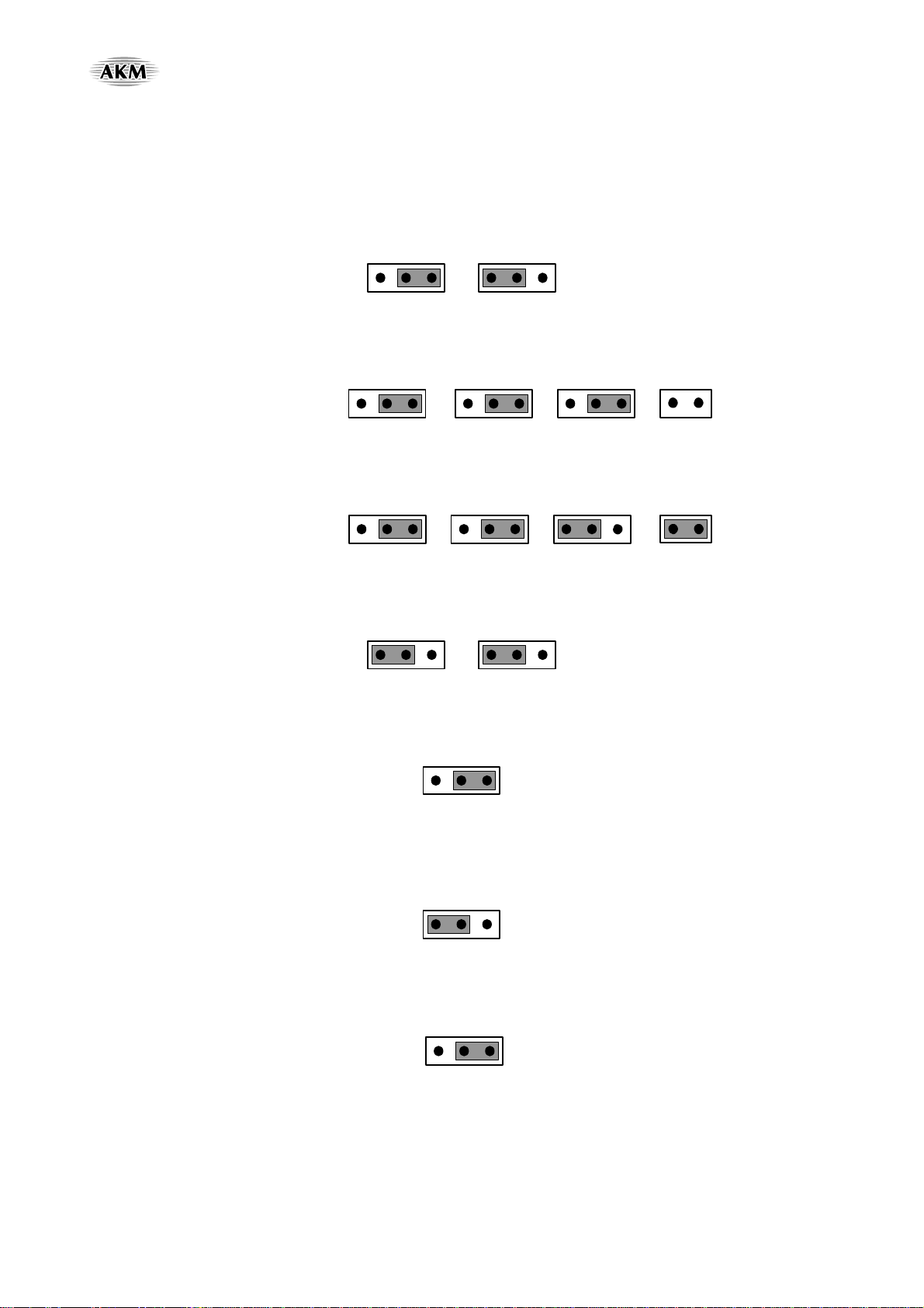
(8) Clock (X’tal1~3, BNC, U10 and internal clock of U11)
The setting of jumper pins is according to ‘Evaluation mode’ set-up.
(9) Function setup
According to following tables (Table 4~Table 7)
(10) LED(DZF)
This is the sign of output for DZF pin.
(11) USB PORT(U13)
A computer can control AK7600VF and AK4114 on this board by the AK7600 control software through this USB
port.
Evaluation Board Manual
Operation sequence
1) Set up Power Supplies (The power should be separated from the source of a power supplier.)
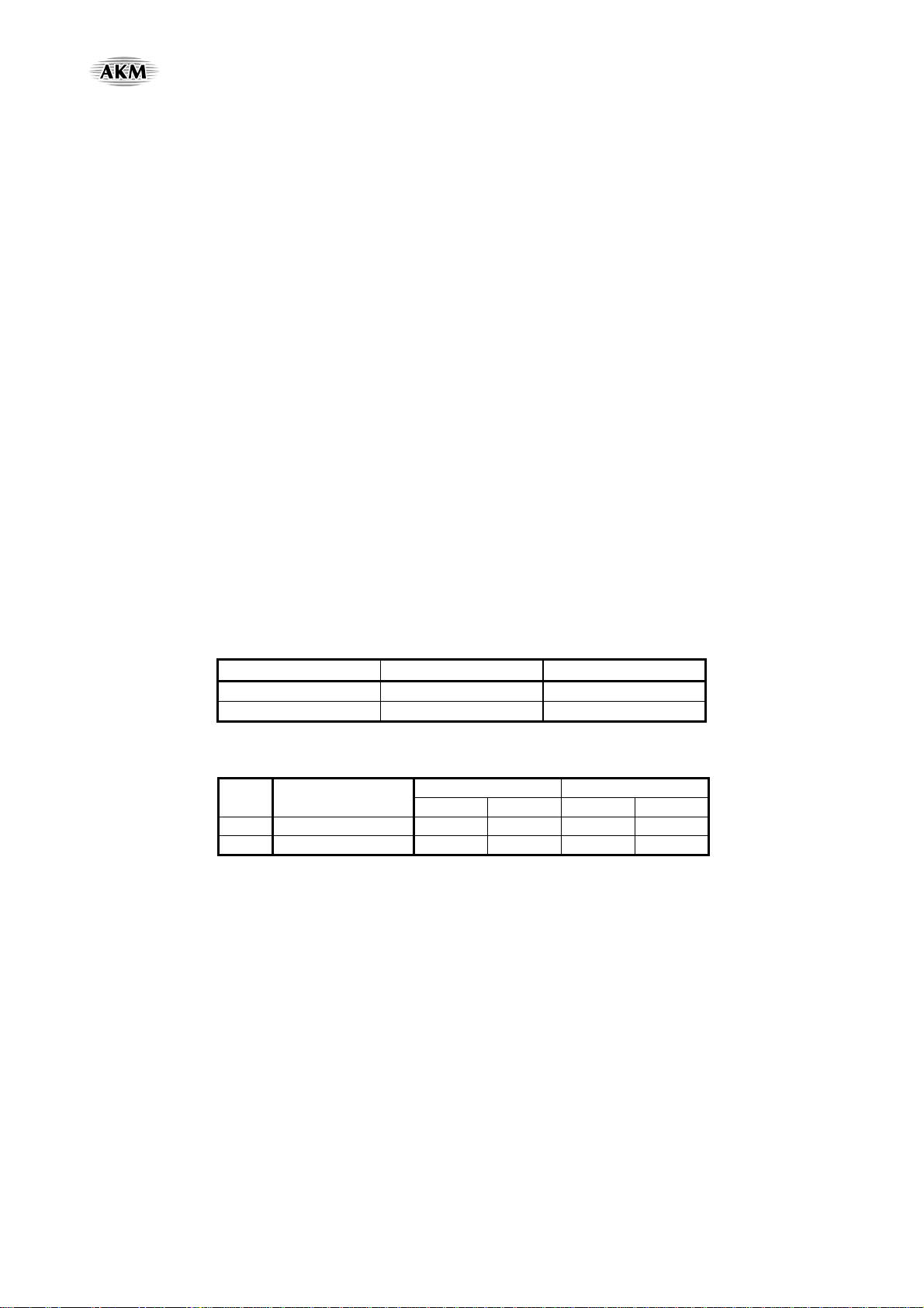
Name of
connector Color of
connector Voltage Used for Comment and attention Default
Setting
+12V Red +12V
Regulator REG1,
Regulator REG2,
Regulator REG3,
OP-Amplifiers
Make sure to be connected by +12V power
supplier. And this connector is used when AVDD
and DVDD(5V-C) of AK7600VF are supplied
from regulator REG1.
And DVDD(3.3V), DVDD(5V) of AK7600VF are
supplied from regulator REG2 and REG3. In this
case, JP18 and JP19 should be SHORT. (Default)
When JP18 is open, the orange connector (J2)
should be supplied +5V.
+12V
-12V Blue -12V OP-Amplifier
This connector should be connected by -12V power
supplier. -12V
+5V
(J2) Orange +4.5 ~
+5.5V
AVDD and
DVDD(5V-C) of
AK7600VF,
Analog input
buffercircuit
This connector is used when AVDD and
DVDD (5V-C) of AK7600VF is power supplied
+5V without regulators. In this case, J18 should be
OPEN.
Open
AGND Black 0V Analog ground
Make sure to be connected by the ground
connection. 0V
DGND Black 0V Digital ground
This connector is used when DGND is supplied
seperatly with AGND. In this case, WIRE1 should
be open. (Default)
0V
Table 1 Power supply lines

[AKD7600-A]
< KM091700> 2008/04
- 4 -
2) Set up the jumper pins and connectors. (According to explanations of ‘Evaluation mode’: P.4 to P.6)
3) USB Connect
Connect the board to PC with the USB cable packed.
It is required to push down the button ‘SW1’ to initialize PIC18F4550, the control device from PC.
4) Power on
Power the board on and start up the AK7600 control software.
5) Setup the control register (According to explanations of ‘Control Software Manual’: P.8 to P.22)
Click the button, ‘Board Init’ on the AK7600 software to initialize.
* When the power is down, DZF pin is off.
Evaluation Mode
(When you use a sub-board, the silk print numbers on the board of jumpers are changed
from the main board JP9 to the sub-board JP1A and the main board JP19 to the sub-board JP2A.)
This evaluation mode is for analog inputs and analog outputs by passing internal ADC and DAC.
(1)Default mode
•Master Mode of AK7600VF (JP8:Master 2-3)
•X’tal2(JP9:XTL 1-2)→XTI pin of AK7600VF
•TX-CLK: CLKO pin signal from AK7600VF(JP1:EXT 2-3)→XTI pin of AK4114
•EXT-BICK : BICK pin signal from AK7600VF(JP3:THR 1-2, JP4:DIR 1-2)→U8→BICK pin of AK4114
•EXT-LRCK:LRCK pin signal from AK7600VF(JP7 : DIR 2-3)→U8→LRCK pin of AK4114
•EXT-MCLK: (JP5: DIR 2-3, JP6: OPEN)
•SDTO: (JP2: OPEN)
•CONT01-DIF bit(D3): I2S (1) /MSB(0) - (on the register setup of the software)
LRCK MCLK (MHz) BICK (MHz)
fs 256fs 64fs
44.1 kHz 11.2896 2.8224
Table 2 System Clocks
LRCK BICK
Mode SDTO1-3 I/O I/O
0 24bit, Left justified H/L O 64fs O
1 24bit, I2S L/H O 64fs O Default
Table 3 Audio Data Format (Stereo mode)

[AKD7600-A]
< KM091700> 2008/04
- 5 -
(2) Master Mode of AK7600VF
:MCLK is from X’tal2(Sub-board:X’tal1A), AK4114, or BNC.(The master mode is only for 256fs speed of
MCLK(11.2896MHz))
(2-1) MCLK (JP8: MASTER 2-3, JP9: EXT 2-3)
(2-1-1) MCLK from X’tal2 (JP9: Master 1-2)
JP9
XTI
XTL EXT
JP8
7600
Slave Master
(2-1-2) MCLK from AK4114(JP5:DIR 2-3, JP6:Open)
JP8
7600
Slave Master
JP9
XTI
XTL EXT
JP5
MCLK
EXT DIR
JP6
BNC GND
OPEN
(2-1-3) MCLK From BNC(JP5:EXT 1-2, JP6:Short)
JP8
7600
Slave Master
JP5
MCLK
EXT DIR
JP9
XTI
XTL EXT
JP6
SHORT
BNC GND
(2-2) BICK(JP3:DIR 1-2, JP4:THR 1-2)
JP3
PHASE
THR INV
JP4
BICK
DIR 64fs
(2-3) LRCK(JP7:DIR 2-3)
JP7
LRCK
1fs DIR
(3) AK4114 Clock (JP1)
(3-1) From X’tal1 (JP1:XTL 1-2)
JP1
XTI
XTL EXT
(3-2) From CLKO pin(TX-CLK) of AK7600VF(JP1:EXT 2-3)
JP1
XTI
XTL EXT

[AKD7600-A]
< KM091700> 2008/04
- 6 -
Other jumper pins set up
(1) Configuration of jumpers for the power supplies (JP18, JP19, and J2)
Power Supplies Jumper Power
Regulator Supply
to AVDD and DVDD(5V-C) :Default JP18:SHORT J2:OPEN
+5V Power Supply without a regulator
to AVDD and DVDD(5V-C) JP18:OPEN Supply +5V to J2
Regulator Supply
to DVDD(5V) :Default JP19:SHORT -
+5V Power Supply without a regulator
to DVDD(5V) JP19:OPEN Supply +5V
to Pin 2 of JP19
Table 4 Power Jumper pins setting
(2)Digital Data SDTO1 pin, SDTO 2 pin, and SDTO 3 pin (JP2)
Power Supplier Side
↑↑
JP2
SDTO2
To DIT
From DIR
SDTO3
To DIT
SDTO1
To DIT
From DIR
↓↓
Universal Area Side
Figure 3 JP2
* Default: Open JP2 for the analog inputs to analog outputs setup.
* When the digital outputs (ADC outputs: SDTO1~3pins) are needed to use, it is necessary to set on the register,
CONT02 SDTO1~3(D5), on the AK7600 software and to link by clip-to-clip between SDTO1~3 and DIT of
JP2 on the board.
(3)Power Supply (JP11, JP14) to AK7600VF (U10)
JP11(AVDD) JP14(DVDD(5V-C))
Default SHORT SHORT
Table 5 Power Supply to AK7600VF
(4) Power Supply (JP10) to AK7600VF (U10) VREFH pin
JP10(AVDD)
Default SHORT
Table 6 Power Supply to VREFH pin of AK7600VF
(5) Power Supply (JP16) to PIC18F4550 (U11)
JP16
DVDD(5V-C) 1-2
USB(U13) 2-3 (Default)
Table 7 Power Supply to PIC18F4550

[AKD7600-A]
< KM091700> 2008/04
- 7 -
Board control
•It is possible to control AKD7600-A via a general USB port. Connect the USB port on board to PC by the packed
cable with the board.
•AK7600 control software is packed with this board. The software operation sequence is included in this evaluation
board manual.
Indication of LED
•This is the signal from the DZF pin (No.16) of Ak7600VF.
DZF pin = “H”: LED on
DZF pin = “L”: LED off

[AKD7600-A]
< KM091700> 2008/04
- 8 -
Control Software Manual
Set-up of the evaluation board and control software
1. Setup the AKD7600-A board according to previous.
2. Connect AKD7600-A to PC with the cable packed. Push down the reset button ‘SW1’ to initialize the USB chip.
(According to following explanation “USB connection”)
3. Insert the CD-ROM labeled “AKD7600-A Evaluation Kit” into the CD-ROM drive.
4. Access the CD-ROM drive and double-click the icon of “AK7600.exe” to set up the program.
(AK7600.exe: This is the control software for AK7600VF.)
5. Then, please evaluate according to “Control software operation flow”.
USB connection
1. Insert the USB cable to the USB port on AKD7600-A board. If there is an error message, device has not been
recognized from the windows, click the message and cancel it.
2. Press the button which is ‘SW1’ on the board, and the windows O.S. will recognize this board automatically.
3. It can be verified to be connected on ‘Human Interface Device (HID)’ of the device manager on the windows.
*Please use a set of a board and software one to one. It is recommended not to use multiple connections.
Control software operation flow
Keep the following flow
1. Activate the software as double-click ‘AK7600.exe’.
2. Click ‘Board Init’ button to initialize the board.
3. Select the needed dialogue to evaluate by changing the setting.
(Note) If the USB cable is removed when the control software is being used, please close the software and start this
operation flow again from first.

[AKD7600-A]
< KM091700> 2008/04
- 9 -
Figure 4 Control software
* This control software is possible to download an execution file to set up the registers, to set up AK4114 and to use the
equalizer. They can be selected by the tab items above. The outside buttons of the tap belong to following explanations.
•PDN: Control of the PDN pin - AK7600VF pin No. 17(ON=High /OFF=Low)
•RSTN: Control of AK7600VF RSTN register)(ON=Normal (Default)/OFF=Reset)
•CS4: Control of AK4114 PDN pin(ON=High /OFF=Low)
•Board Init: To initialize of AKD7600-A
•READ: To read out the registers of AK7600VF CONT00~02 on the software screen
•READ ALL: To read out the present condition of the register setup on a text file
•WRITE ALL: To load the register condition setup by a text file has been created a register setup
•EXIT: To exit this software operation

[AKD7600-A]
< KM091700> 2008/04
- 10 -
(1) Register Set-up
Figure 5 Register Control Screen
COMMAND Register
Name D7 D6 D5 D4 D3 D2 D1 D0
01H Control 00 0 0 0 0 0 PMADC PMDAC RSTN
Default 0 0 0 0 0 1 1 1
Table 8 Registers Default Setup CONT00
COMMAND Register
Name D7 D6 D5 D4 D3 D2 D1 D0
02H Control 01 DZD3 DZD2 DZD1 DZLH DIF 0 0 SMUTE
Default 0 0 0 0 1 0 0 0
Table 9 Registers Default Setup CONT01
COMMAND Register
Name D7 D6 D5 D4 D3 D2 D1 D0
03H Control 02 LRCK BICK MCKO Reserved DO3 DO2 DO1 0
Default 0 0 0 0 0 0 0 0
Table 10 Registers Default Setup CONT02

[AKD7600-A]
< KM091700> 2008/04
- 11 -
Register Name: CONT00
D7 D6 D5 D4 D3 D2 D1 D0
COMMAND (01H) 0 0 0 0 0 0 0 1
Setting bit (1byte) 0 0 0 0 0 PMADC PMDAC RSTN
R/W RD RD RD RD RD R/W R/W R/W
Default 0 0 0 0 0 1 1 0
It is necessary to change a bit for outputs of the digital signals, PMADC bit(D2), PMDAC bit(D1).
•RSTN: Internal timing reset
0: Reset (The DZF pin goes to “H” but Register values are not initialized.)
1:NormalOperation
•PMDAC: DAC1-3 power management
0: Power Down (All DAC’s)
1: Normal Operation (Default)
•PMADC: ADC power management
0:PowerDown
1: Normal Operation (Default)
Register Name: CONT01
D7 D6 D5 D4 D3 D2 D1 D0
COMMAND (02H) 0 0 0 0 0 0 1 0
Setting bit (1byte) DZD3 DZD2 DZD1 DZLH DIF 0 0 SMUTE
R/W R/W R/W R/W R/W R/W RD RD R/W
Default 0 0 0 0 1 0 0 0
(Note) Writing to RD bits is ignored.
•DZD3: DZF pin setting
0: Indicate Zero detect of DAC3 at DZF pin
1: Ignore Zero detect
•DZD2: DZF pin setting
0: Indicate Zero detect of DAC2 at DZF pin
1: Ignore Zero detect
•DZD1: DZF pin setting
0: Indicate Zero detect of DAC1 at DZF pin
1: Ignore Zero detect
•DZLH: DZF pin setting
0: Output “H” as a result of DZF pin zero detection
1: Output “L” as a result of DZF pin zero detection
•DIF: Digital output format (DIF mode setting)
0: Left justified mode
1:I
2S mode (default)
•SMUTE: Soft Mute enable
0:NormalOperation
1: Soft Mute execute for all DAC’s

[AKD7600-A]
< KM091700> 2008/04
- 12 -
D7 D6 D5 D4 DAC3 DAC2 DAC1 DZF pin output Level
0 0 0 0 Zero Zero Zero H
0 0 1 0 Zero Zero - H
0 1 0 0 Zero - Zero H
0 1 1 0 Zero - - H
1 0 0 0 - Zero Zero H
1 0 1 0 - Zero - H
1 1 0 0 - - Zero H
1 1 1 0 - - - H
0 0 0 1 Zero Zero Zero L
0 0 1 1 Zero Zero - L
0 1 0 1 Zero - Zero L
0 1 1 1 Zero - - L
1 0 0 1 - Zero Zero L
1 0 1 1 - Zero - L
1 1 0 1 - - Zero L
1 1 1 1 - - - L
Table 11 DZF pin Setup
Register Name: CONT02
D7 D6 D5 D4 D3 D2 D1 D0
COMMAND (03H) 0 0 0 0 0 0 1 1
Setting bit (1byte) LRCK BICK MCKO Reserved DO3 DO2 DO1 0
R/W R/W R/W R/W R/W R/W R/W R/W RD
Default 0 0 0 0 0 0 0 0
•LRCK: LR Clock output enable
0: LRCK pin outputs “L”
1: Output LRCK to the LRCK pin
•BICK: Bit Clock output enable
0: BICK pin outputs “L”
1: Output BIT clock (64fs) to the BICK pin
•MCKO: Master Clock output enable
0: CLKO pin outputs “L”
1: Output master clock (256fs) to the CLKO pin
•Reserved: Write “0” into this bit.
•DO3: SDTO3 Signal output enable
0: SDTO3 pin outputs “L”
1: Output audio data to the SDTO3 pin
•DO2: SDTO2 Signal output enable
0: SDTO2 pin outputs “L”
1: Output audio data to the SDTO2 pin
•DO1: SDTO1 Signal output enable
0: SDTO1 pin outputs “L”
1: Output audio data to the SDTO1 pin

[AKD7600-A]
< KM091700> 2008/04
- 13 -
(2) Set-up for AK4114
Figure 6 AK4114 Control Screen
•AK4114 can be setup to make output or to get input.
AK4114 Setting
MCLK
Frequency of main clock output from AK4114
0 : 256fs
1 : 256fs
2 : 512fs
3 : 128fs
CM
Master clock operation mode of AK4114
0 : CM = 00
1 : CM = 01
2 : CM = 10
3 : CM = 11
DIF
Format setup of AK4114 I/O
0 : 16bit Right ( Output )
1 : 18bit Right ( Output )
2 : 20bit Right ( Output )
3 : 24bit Right ( Output )
4 : 24bit Left ( Output )
5 : 24bit I2S ( Output )
6 : 24bit Left ( Input )
7 : 24bit I2S ( Input )
Table 12 AK4114 Set-up

[AKD7600-A]
< KM091700> 2008/04
- 14 -
(3) Equalizer
Figure 7 Equalizer Screen
*The signals from ADC can be adjusted on this [Equalizer] window and sent to DAC1, DAC2 and DAC3.
*Please press the enter key after numbers are put in the boxes for this equalizer set-up.
*After entered numbers which are filter coefficients of equalizers and coefficients of the function to set up,
click [send] buttons to be executed properly.
Filter Set
*Input a hexadecimal number of 4 ciphers for 16-bit
single coefficients.
e.g. : If the number from the table of the coefficient is
0x4000, enter 0x4000.
*Input a hexadecimal number of 8 ciphers for 16-bit
double coefficients.
Use a hexadecimal number of 7 ciphers
from the second number of the written 8 numbers
on the tables of the coefficient register set-up
and add 0 at the end of the 7 available numbers.
e.g. : If the number from the table of the coefficient
is 0x04000000,
enter 0x40000000.
Figure 8Filter Set

[AKD7600-A]
< KM091700> 2008/04
- 15 -
■Explanation for the each function
Function
Figure 9 Function
Command 40H Shift Setting(Multiple) R/W Default Value
Data 1 (2byte) LI1 Coefficient 1bit left (x2) R/W 0x2000
Data 2 (2byte) RI1 Coefficient 1bit left (x2) R/W 0x2000
Data 3 (2byte) LT Coefficient 1bit left (x2) R/W 0x4000
Data 4 (2byte) LO1 Coefficient 1bit left (x2) R/W 0x0000
Data 5 (2byte) LO2 Coefficient 1bit left (x2) R/W 0x0000
Command 41H Shift Setting(Multiple) R/W Default Value
Data 1 (2byte) LI2 Coefficient 1bit left (x2) R/W 0x2000
Data 2 (2byte) RI2 Coefficient 1bit left (x2) R/W 0x2000
Data 3 (2byte) RT Coefficient 1bit left (x2) R/W 0x4000
Data 4 (2byte) RO1 Coefficient 1bit left (x2) R/W 0x0000
Data 5 (2byte) RO2 Coefficient 1bit left (x2) R/W 0x0000
Z-n
Z-
1
Z-
1
Z-
1
Z-
1
Z-
1
Z-
1
Z-
1
Z-
1
Z-n
a10
LI1
RI1
LI2
RI2
D1
D2
a11
a12
a20
a21
a22
b11
b12
b21
b22
RT
LO1
RO1
LO2
RO2
Function All 16bit 1bit Left

[AKD7600-A]
< KM091700> 2008/04
- 16 -
Command 42H Shift Setting(Multiple) R/W Default Value
Data 1 (2byte) A12 Coefficient 1bit left (x2) R/W 0x0000
Data 2 (2byte) A11 Coefficient 1bit left (x2) R/W 0x0000
Data 3 (2byte) A10 Coefficient 1bit left (x2) R/W 0x4000
Data 4 (2byte) B12 Coefficient 1bit left (x2) R/W 0x0000
Data 5 (2byte) B11 Coefficient 1bit left (x2) R/W 0x0000
Command 43H Shift Setting(Multiple) R/W Default Value
Data 1 (2byte) A22 Coefficient 1bit left (x2) R/W 0x0000
Data 2 (2byte) A21 Coefficient 1bit left (x2) R/W 0x0000
Data 3 (2byte) A20 Coefficient 1bit left (x2) R/W 0x4000
Data 4 (2byte) B22 Coefficient 1bit left (x2) R/W 0x0000
Data 5 (2byte) B21 Coefficient 1bit left (x2) R/W 0x0000
(Note) All data are R/W.
Table 13 Function
ATT
Attenuate input data for both Left and Right channels.
Figure 10 ATT
Command 44H Shift Setting(Multiple) R/W Default
Value
Data 1 (2byte) Pre EQ ATT setting coefficient 1bit left (x2) R/W 0x4000
Data 2 (2byte) Dummy 1bit left (x2) R/W 0x0000
Data 3 (2byte) Dummy 1bit left (x2) R/W 0x0000
Data 4 (2byte) Dummy 1bit left (x2) R/W 0x0000
Data 5 (2byte) Dummy 1bit left (x2) R/W 0x0000
(Note) All data are R/W.
Table 14 ATT
EQ Setting
Figure 11 Equalizer
<< 1
<< 1
EQ1 EQ2 EQ3 EQ4
Z-1
EQ0
Lch
Rch
Z-1
Z-1 Z-1
Z-1 Z-1
Z-1
Z-1
Z-1 Z-1
Z-1 Z-1
A
0
A
1
A
2
B1
B2
A
0
A
1
A
2
B1
B2
A
0
A
1
A
2
B1
B2
A
0
A
1
A
2
B1
B2
A
0
A
1
A
2
B1
B2

[AKD7600-A]
< KM091700> 2008/04
- 17 -
Command 81H Shift Setting(Multiple) R/W Default Value
Data 1 (4byte) EQ0 A2 Coefficient 1bit left (x2) R/W 0x00000000
Data 2 (4byte) EQ0 A1 Coefficient 1bit left (x2) R/W 0x00000000
Data 3 (4byte) EQ0 A0 Coefficient 1bit left (x2) R/W 0x04000000
Data 4 (4byte) EQ0 B2 Coefficient 1bit left (x2) R/W 0x00000000
Data 5 (4byte) EQ0 B1 Coefficient 1bit left (x2) R/W 0x00000000
Command 82H Shift Setting(Multiple) R/W Default Value
Data 1 (4byte) EQ1 A2 Coefficient 1bit left (x2) R/W 0x00000000
Data 2 (4byte) EQ1 A1 Coefficient 1bit left (x2) R/W 0x00000000
Data 3 (4byte) EQ1 A0 Coefficient 1bit left (x2) R/W 0x04000000
Data 4 (4byte) EQ1 B2 Coefficient 1bit left (x2) R/W 0x00000000
Data 5 (4byte) EQ1 B1 Coefficient 1bit left (x2) R/W 0x00000000
Command 83H Shift Setting(Multiple) R/W Default Value
Data 1 (4byte) EQ2 A2 Coefficient 1bit left (x2) R/W 0x00000000
Data 2 (4byte) EQ2 A1 Coefficient 1bit left (x2) R/W 0x00000000
Data 3 (4byte) EQ2 A0 Coefficient 1bit left (x2) R/W 0x04000000
Data 4 (4byte) EQ2 B2 Coefficient 1bit left (x2) R/W 0x00000000
Data 5 (4byte) EQ2 B1 Coefficient 1bit left (x2) R/W 0x00000000
Command 45H Shift Setting(Multiple) R/W Default Value
Data 1 (2byte) EQ3 A2 Coefficient 1bit left (x2) R/W 0x0000
Data 2 (2byte) EQ3 A1 Coefficient 1bit left (x2) R/W 0x0000
Data 3 (2byte) EQ3 A0 Coefficient 1bit left (x2) R/W 0x4000
Data 4 (2byte) EQ3 B2 Coefficient 1bit left (x2) R/W 0x0000
Data 5 (2byte) EQ3 B1 Coefficient 1bit left (x2) R/W 0x0000
Command 46H Shift Setting(Multiple) R/W Default Value
Data 1 (2byte) EQ4 A2 Coefficient 1bit left (x2) R/W 0x0000
Data 2 (2byte) EQ4 A1 Coefficient 1bit left (x2) R/W 0x0000
Data 3 (2byte) EQ4 A0 Coefficient 1bit left (x4) R/W 0x2000
Data 4 (2byte) EQ4 B2 Coefficient 1bit left (x2) R/W 0x0000
Data 5 (2byte) EQ4 B1 Coefficient 1bit left (x2) R/W 0x0000
(Note) All data are R/W.
Table 15 Equalizer

[AKD7600-A]
< KM091700> 2008/04
- 18 -
F-ATT, R-ATT, N-ATT
Amplify or regulate each Front (L1, R1), Rear (L2, R2) and SW (L3, R3) X’Over filter input data.
Figure 12 F-ATT, R-ATT, and N-ATT
Command 47H Shift Setting(Multiple) R/W Default Value
Data 1 (2byte) Front ATT setting coefficient 1bit left (x2) R/W 0x4000
Data 2 (2byte) Rear ATT setting coefficient 1bit left (x2) R/W 0x4000
Data 3 (2byte) SW(NF) ATT setting coefficient 1bit left (x2) R/W 0x4000
Data 4 (2byte) Dummy 1bit left (x2) R/W 0x0000
Data 5 (2byte) Dummy 1bit left (x2) R/W 0x0000
(Note) All data are R/W.
Table 16 F-ATT, R-ATT, and N-ATT
X’Over filter (HPF & LPF)
Figure 13 X’Over Filter
Command 84H Shift Setting(Multiple) R/W Default Value
Data 1 (4byte) HPF1-1 A2 Coefficient 1bit left (x2) R/W 0x00000000
Data 2 (4byte) HPF1-1 A1 Coefficient 1bit left (x2) R/W 0x00000000
Data 3 (4byte) HPF1-1 A0 Coefficient 1bit left (x2) R/W 0x04000000
Data 4 (4byte) HPF1-1 B2 Coefficient 1bit left (x2) R/W 0x00000000
Data 5 (4byte) HPF1-1 B1 Coefficient 1bit left (x2) R/W 0x00000000
Command 85H Shift Setting(Multiple) R/W Default Value
Data 1 (4byte) HPF1-2 A2 Coefficient 1bit left (x2) R/W 0x00000000
Data 2 (4byte) HPF1-2 A1 Coefficient 1bit left (x2) R/W 0x00000000
Data 3 (4byte) HPF1-2 A0 Coefficient 1bit left (x2) R/W 0x04000000
Data 4 (4byte) HPF1-2 B2 Coefficient 1bit left (x2) R/W 0x00000000
Data 5 (4byte) HPF1-2 B1 Coefficient 1bit left (x2) R/W 0x00000000
<< 1
<< 1
Z-1
n
First step Second step
Z-1
Z-1
Z-1
Z-1
Z-1
A
0
A
1
A
2
B1
B2
A
0
A
1
A
2
B1
B2
HPF1-1
HPF2-1
LPF-1
HPF1-2
HPF2-2
LPF-2

[AKD7600-A]
< KM091700> 2008/04
- 19 -
Command 86H Shift Setting(Multiple) R/W Default Value
Data 1 (4byte) HPF2-1 A2 Coefficient 1bit left (x2) R/W 0x00000000
Data 2 (4byte) HPF2-1 A1 Coefficient 1bit left (x2) R/W 0x00000000
Data 3 (4byte) HPF2-1 A0 Coefficient 1bit left (x2) R/W 0x04000000
Data 4 (4byte) HPF2-1 B2 Coefficient 1bit left (x2) R/W 0x00000000
Data 5 (4byte) HPF2-1 B1 Coefficient 1bit left (x2) R/W 0x00000000
Command 87H Shift Setting(Multiple) R/W Default Value
Data 1 (4byte) HPF2-2 A2 Coefficient 1bit left (x2) R/W 0x00000000
Data 2 (4byte) HPF2-2 A1 Coefficient 1bit left (x2) R/W 0x00000000
Data 3 (4byte) HPF2-2 A0 Coefficient 1bit left (x2) R/W 0x04000000
Data 4 (4byte) HPF2-2 B2 Coefficient 1bit left (x2) R/W 0x00000000
Data 5 (4byte) HPF2-2 B1 Coefficient 1bit left (x2) R/W 0x00000000
Command 88H Shift Setting(Multiple) R/W Default Value
Data 1 (4byte) LPF-1 A2 Coefficient 1bit left (x2) R/W 0x00000000
Data 2 (4byte) LPF-1 A1 Coefficient 1bit left (x2) R/W 0x00000000
Data 3 (4byte) LPF-1 A0 Coefficient 1bit left (x2) R/W 0x04000000
Data 4 (4byte) LPF-1 B2 Coefficient 1bit left (x2) R/W 0x00000000
Data 5 (4byte) LPF-1 B1 Coefficient 1bit left (x2) R/W 0x00000000
Command 89H Shift Setting(Multiple) R/W Default Value
Data 1 (4byte) LPF-2 A2 Coefficient 1bit left (x2) R/W 0x00000000
Data 2 (4byte) LPF-2 A1 Coefficient 1bit left (x2) R/W 0x00000000
Data 3 (4byte) LPF-2 A0 Coefficient 1bit left (x2) R/W 0x04000000
Data 4 (4byte) LPF-2 B2 Coefficient 1bit left (x2) R/W 0x00000000
Data 5 (4byte) LPF-2 B1 Coefficient 1bit left (x2) R/W 0x00000000
(Note) All data are R/W.
Table 17 X’Over filter (HPF & LPF)
F-Gain, R-Gain, N-Gain
Amplify or regulate each Front (L1, R1), Rear (L2, R2) and SW (L3, R3) X’Over filter output data.
Figure 14 F-Gain, R-Gain, N-Gain
<< 1
<< 1

[AKD7600-A]
< KM091700> 2008/04
- 20 -
Command 48H Shift Setting(Multiple) R/W Default Value
Data 1 (2byte) Front Gain setting coefficient 1bit left (x2) R/W 0x4000
Data 2 (2byte) Rear Gain setting coefficient 1bit left (x2) R/W 0x4000
Data 3 (2byte) SW(NF) Gain setting coefficient 1bit left (x2) R/W 0x4000
Data 4 (2byte) Dummy 1bit left (x2) R/W 0x0000
Data 5 (2byte) Dummy 1bit left (x2) R/W 0x0000
Table 18 F-Gain, R-Gain, and N-Gain
Delay Time Setting (fs step)
1. D1 or D2 delay time setting of Function
2. Delay time setting of each FL, FR, RR, RL, NL and NR channel
* (1/fs = 1/44100 = approximately 0.0226ms) = one unit.
Figure 15 Delay Time
Command 49H Setting Unit R/W Default Value
Data 1 (2byte) Function2 D1 delay time
Set range (0x0000~0x002D) Delay time: 1/fs unit R/W 0x0000
Data 2 (2byte) Front L1 out delay time
Set range (0x0000~0x031A) Delay time: 1/fs unit R/W 0x0000
Data 3 (2byte) Rear L2 out delay time
Set range (0x0000~0x031A) Delay time: 1/fs unit R/W 0x0000
Data 4 (2byte) SW L3 out delay time
Set range (0x0000~0x031A) Delay time: 1/fs unit R/W 0x0000
Data 5 (2byte) Dummy - R/W 0x0000
Delay Memory 1word=24bit
18ms Delay = 794word (44.1 kHz x 0.018)
Lch input
FL
RL
NL
L1 out (Front)
L2 out (Rear)
L3 out (SW)
Delay Memory 1word=24bit
18ms Delay = 794word (44.1 kHz x 0.018)
Rch input
FR
RR
NL
R1 out (Front)
R2 out (Rear)
R3 out (SW)
Table of contents
Other AKM Motherboard manuals