AKM AKD4396-SBW User manual

[AKD4396-SBW]
<KM078103> 1 2011/03
General Description
The AKD4396-SBW is an evaluation board for AK4396, which is 192kHz sampling 24Bit ΔΣ DAC. The
AKD4396-SBW includes a LPF which can add differential analog outputs from the AK4396 and also has a
digital interface. Therefore, it is easy to evaluate the AK4396.
Ordering Guide
AKD4396-SBW --- Evaluation board for AK4396
Function
On-board Analog output buffer circuit
On-board digital audio interface. (AK4113)
COAX In AK4113 AK4396
2nd Order LPF
Rch
Lch
DIR
Opt In
Figure 1 Block diagram
* Circuit diagram and PCB layout are attached at the end of this manual.
COAX is recommended for an evaluation of the Sound quality.
Evaluation board
A
KD4396-SB
W
Rev.2

[AKD4396-SBW]
<KM078103> 2 2011/03
Operation sequence
1) Set up the power supply lines. (See “Other jumpers set-up”.)
Name Color Voltage Comments Attention
+15V Red
+12∼+15V Regulator,
Power supply for Op-amp. This jack is always needed. Power line
-15V Blue
-12∼-15V Regulator,
Power supply for Op-amp. This jack is always needed. Power line
AGND Black 0V GND This jack is always needed.
Table 1 Set up of power supply lines
Each supply line should be distributed from the power supply unit.
2) Set-up the jumper pins
3) Set-up the DIP switches. (See the followings.)
4) Power on
The AK4396 should be reset once bringing SW1 (PDN) “L” upon power-up.

[AKD4396-SBW]
<KM078103> 3 2011/03
Evaluation mode
1. DIR(COAX) (default)
J1 is used for the evaluation using such as CD test disk. The DIR generates MCLK, BICK and LRCK SDATA from the
received data through BNC connector (J1). Setting of jumper is shown below.
COAX is recommended for an evaluation of the Sound quality.
JP1
OPT
COAX
BNC
(Default)
Figure 2 Jumper setting, when using DIR
2. DIR(Optical Link)
PORT1 is used for the evaluation using such as CD test disk. The DIR generates MCLK, BICK and LRCK SDATA from the
received data through optical connector (PORT2: TORX176). Setting of jumper is shown below.
JP1
OPT
COAX
PORT2
Figure 3 Jumper setting, when using DIR
3. All clocks are fed through the PORT1.
-R9, R12, R13, R14 : open
-R10, R15, R19, R20 : 100Ω or short (0 Ω)
DIP Switch setting
[SW2]: AK4113 setting
No. Pin OFF ON Default
1 OCKS1 ON
2 OCKS0
AK4113 Master Clock setting
Refer to Table4 OFF
Table 2 SW2 setting
[SW3]: AK4396 setting
No. Pin OFF ON Default
1
-
2 P/S Serial mode (Note) Parallel mode ON
Note : When using the serial mode, R5 and R17 should be removed.
Table 3 SW3 setting

[AKD4396-SBW]
<KM078103> 4 2011/03
The frequency of the master clock output is set by OCKS0 and OCKS1 as shown in Table 4.
OCKS1 OCKS0 MCLK Frequency
0 0 256fs @fs=88.2/96kHz
1 0 512fs @32/44.1/48kHz
1 1 128fs @176.4/192kHz
Default
Table 4 MCLK Clock
SW1 setting
[SW1](PDN): Reset of AK4396. Select “H” during operation.
External Analog Circuit
The differential output circuit and LPF is implemented on board. The differential outputs of AK4396 is buffered by non-inverted circuit(2nd
order LPF, fc=182k, Q=0.637, G=+3.9dB). LPF adds differential outputs(1st order LPF, fc=284k, G=-0.84dB). NJM5534D is used for
op-amp on this board that has low noise and high voltage torelance characteristics. Analog signal is output via BNC connectors on the board.
The output level is about 2.8Vrms (typ@VREF=5.0V) by BNC.
330
100u 180
AOUTL-
10k
3.9
n
1.2k
680
3.3n
6
4
3
2
7
10u
0.1u
0.1u 10u
10u
NJM5534D
330
100u 180
AOUTL+
10k
3.9n
1.2k
680
3.3n
6
4
3
2
7
10u
0.1u
0.1
u
10u
NJM5534D 0.1u
+
NJM5534D
0.1u 10u
100
4
3
2
1.0n
620
620
560
7
+
+
+
+
-
+
-
+
+
+
-
+
+
1.0n
Lch
-15
+15
6
560
Figure 4 External Analog Filter
AKD4396-SBW
Filter 40kHz (Double) 80kHz (quad)
Internal Filter -0.3dB -1dB
External LPF -0.19dB -0.85dB
Total -0.49dB -1.85dB
This table shows typical value.
Table 5 Frequency Responses

[AKD4396-SBW]
<KM078103> 5 2011/03
2. Control Software Manual
Set-up of evaluation board and control software
1.Set up the AKD4396-SBW according to previous term.
2.Connect IBM-AT compatible PC with AKD4396-SBW by 10-line type flat cable (packed with AKD4396-SBW).
Take care of the direction of 10pin header. (Please install the driver in the CD-ROM when this control software is
used on Windows 2000/XP. Please refer “Installation Manual of Control Software Driver by AKM device control
software”. In case of Windows95/98/ME, this installation is not needed. This control software does not operate on
Windows NT.)
3.Insert the CD-ROM labeled “AKD4396-SBW Evaluation Kit” into the CD-ROM drive.
4.Access the CD-ROM drive and double-click the icon of “akd4396-sbw.exe” to set up the control program.
5.Then please evaluate according to the follows.
Operation flow
Keep the following flow.
1. Set up the control program according to explanation above.
2. Click “Port Reset” button.
Explanation of each buttons
1. [Port Reset] : Set up the USB interface board (AKDUSBIF-A) .
2. [Write default] : Initialize the register of AK4396.
3. [All Write] : Write all registers that is currently displayed.
4. [Function1] : Dialog to write data by keyboard operation.
5. [Function2] : Dialog to write data by keyboard operation.
6. [Function3] : The sequence of register setting can be set and executed.
7. [Function4] : The sequence that is created on [Function3] can be assigned to buttons and
executed.
8. [Function5]: The register setting that is created by [SAVE] function on main window can
be assigned to buttons and executed.
9. [SAVE] : Save the current register setting.
10. [OPEN] : Write the saved values to all register.
11. [Write] : Dialog to write data by mouse operation.
Indication of data
Input data is indicated on the register map. Red letter indicates “H” or “1” and blue one indicates “L” or “0”. Blank is
the part that is not defined in the datasheet.

[AKD4396-SBW]
<KM078103> 6 2011/03
Explanation of each dialog
1. [Write Dialog]: Dialog to write data by mouse operation
There are dialogs corresponding to each register.
Click the [Write] button corresponding to each register to set up the dialog. If you check the check box, data
becomes “H” or “1”. If not, “L” or “0”.
If you want to write the input data to AK4396, click [OK] button. If not, click [Cancel] button.
2. [Function1 Dialog] : Dialog to write data by keyboard operation
Address Box: Input registers address in 2 figures of hexadecimal.
Data Box: Input registers data in 2 figures of hexadecimal.
If you want to write the input data to AK4396, click [OK] button. If not, click [Cancel] button.
3. [Function2 Dialog] : Dialog to evaluate ATT
Address Box: Input registers address in 2 figures of hexadecimal.
Start Data Box: Input starts data in 2 figures of hexadecimal.
End Data Box: Input end data in 2 figures of hexadecimal.
Interval Box: Data is written to AK4642 by this interval.
Step Box: Data changes by this step.
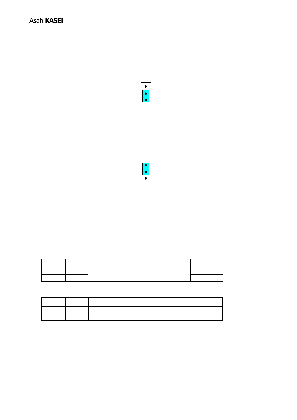
Mode Select Box:
If you check this check box, data reaches end data, and returns to start data.
[Example] Start Data = 00, End Data = 09
Data flow: 00 01 02 03 04 05 06 07 08 09 09 08 07 06 05 04 03 02 01 00
If you do not check this check box, data reaches end data, but does not return to start data.
[Example] Start Data = 00, End Data = 09
Data flow: 00 01 02 03 04 05 06 07 08 09
If you want to write the input data to AK4396, click [OK] button. If not, click [Cancel] button.

[AKD4396-SBW]
<KM078103> 7 2011/03
4. [Save] and [Open]
4-1. [Save]
Save the current register setting data. The extension of file name is “akr”.
(Operation flow)
(1) Click [Save] Button.
(2) Set the file name and push [Save] Button. The extension of file name is “akr”.
4-2. [Open]
The register setting data saved by [Save] is written to AK4396. The file type is the same as [Save].
(Operation flow)
(1) Click [Open] Button.
(2) Select the file (*.akr) and Click [Open] Button.

[AKD4396-SBW]
<KM078103> 8 2011/03
5. [Function3 Dialog]
The sequence of register setting can be set and executed.
(1) Click [F3] Button.
(2) Set the control sequence.
Set the address, Data and Interval time. Set “-1” to the address of the step where the sequence should be paused.
(3) Click [Start] button. Then this sequence is executed.
The sequence is paused at the step of Interval="-1". Click [START] button, the sequence restarts from the paused step.
This sequence can be saved and opened by [Save] and [Open] button on the Function3 window. The extension of file
name is “aks”.
Figure 5. Window of [F3]

[AKD4396-SBW]
<KM078103> 9 2011/03
6. [Function4 Dialog]
The sequence that is created on [Function3] can be assigned to buttons and executed. When [F4] button is clicked, the
window as shown in Figure 6 opens.
Figure 6. [F4] window

[AKD4396-SBW]
<KM078103> 10 2011/03
6-1. [OPEN] buttons on left side and [START] buttons
(1) Click [OPEN] button and select the sequence file (*.aks).
The sequence file name is displayed as shown in Figure 7.
Figure 7. [F4] window(2)
(2) Click [START] button, then the sequence is executed.
3-2. [SAVE] and [OPEN] buttons on right side
[SAVE] : The sequence file names can assign be saved. The file name is *.ak4.
[OPEN] : The sequence file names assign that are saved in *.ak4 are loaded.
3-3. Note
(1) This function doesn't support the pause function of sequence function.
(2) All files need to be in same folder used by [SAVE] and [OPEN] function on right side.
(3) When the sequence is changed in [Function3], the file should be loaded again in order to reflect the
change.

[AKD4396-SBW]
<KM078103> 11 2011/03
7. [Function5 Dialog]
The register setting that is created by [SAVE] function on main window can be assigned to buttons and executed. When
[F5] button is clicked, the following window as shown in Figure 8opens.
Figure 8. [F5] window
7-1. [OPEN] buttons on left side and [WRITE] button
(1) Click [OPEN] button and select the register setting file (*.akr).
(2) Click [WRITE] button, then the register setting is executed.
7-2. [SAVE] and [OPEN] buttons on right side
[SAVE] : The register setting file names assign can be saved. The file name is *.ak5.
[OPEN] : The register setting file names assign that are saved in *.ak5 are loaded.
7-3. Note
(1) All files need to be in same folder used by [SAVE] and [OPEN] function on right side.
(2) When the register setting is changed by [Save] Button in main window, the file should be loaded again in
order to reflect the change.

[AKD4396-SBW]
<KM078103> 12 2011/03
Measurement Results
[Measurement condition]
•Measurement unit : Audio Precision System two Cascade (AP2)
•MCLK : 512fs (44.1kHz), 256fs (96kHz), 128fs (192kHz)
•BICK : 64fs
•fs : 44.1kHz, 96kHz, 192kHz
•Bit : 24bit
•Power Supply : AVDD= DVDD=5V
•Interface : Internal DIR (48kHz, 96kHz, 192kHz)
•Temperature : Room
fs=44.1kHz
Parameter Input signal Measurement filter Results
S/(N+D) 1kHz, 0dB 20kLPF 99.4 dB
DR 1kHz, -60dB 22kLPF, A-weighted 119.0 dB
S/N “0” data 22kLPF, A-weighted 119.0 dB
fs=96kHz
Parameter Input signal Measurement filter Results
S/(N+D) 1kHz, 0dB 40kLPF 99.0 dB
DR 1kHz, -60dB 40kLPF 114.0 dB
DR 1kHz, -60dB 22kLPF, A-weighted 119.3 dB
S/N “0” data 40kLPF 114.0 dB
S/N “0” data 22kLPF, A-weighted 119.3 dB
fs=192kHz
Parameter Input signal Measurement filter Results
S/(N+D) 1kHz, 0dB 40kLPF 98.7 dB
DR 1kHz, -60dB 40kLPF 111.2 dB
DR 1kHz, -60dB 22kLPF, A-weighted 116.4 dB
S/N “0” data 40kLPF 113.6 dB
S/N “0” data 22kLPF, A-weighted 119.0 dB

[AKD4396-SBW]
<KM078103> 13 2011/03
Plots
(fs=44.1kHz)
A
KM AK4396 FFT fs=44.1kHz
AVDD=DVDD=5V, 0dBFS input
20 20k50 100 200 500 1k 2k 5k 10k
Hz
-160
+0
-150
-140
-130
-120
-110
-100
-90
-80
-70
-60
-50
-40
-30
-20
-10
d
B
r
A
Figure 9 FFT (fin=1kHz, Input Level=0dBFS)
A
KM AK4396 FFT plot fs=44.1kHz
AVDD=DVDD=5V, -60dBFS input
-160
+0
-150
-140
-130
-120
-110
-100
-90
-80
-70
-60
-50
-40
-30
-20
-10
d
B
r
A
20 20k50 100 200 500 1k 2k 5k 10k
Hz
Figure 10 FFT (fin=1kHz, Input Level=-60dBFS)

[AKD4396-SBW]
<KM078103> 14 2011/03
(fs=44.1kHz)
A
KM AK4396 FFT plot fs=44.1kHz
AVDD=DVDD=5V, No signal input
-160
+0
-150
-140
-130
-120
-110
-100
-90
-80
-70
-60
-50
-40
-30
-20
-10
d
B
r
A
20 20k50 100 200 500 1k 2k 5k 10k
Hz
Figure 11 FFT (Noise Floor)
A
KM AK4396 FFT fs=44.1kHz
AVDD=DVDD=5V, 0dBFS input, outband noize
-160
+0
-150
-140
-130
-120
-110
-100
-90
-80
-70
-60
-50
-40
-30
-20
-10
d
B
r
A
20 100k50 100 200 500 1k 2k 5k 10k 20k 50k
Hz
Figure 12 FFT (Out of band noise)
(fs=44.1kHz)

[AKD4396-SBW]
<KM078103> 15 2011/03
A
KM AK4396 THD+Nvs Input Level fs=44.1kHz
AVDD=DVDD=5V, 0dBFS
-140 +0-130 -120 -110 -100 -90 -80 -70 -60 -50 -40 -30 -20 -10
dBFS
-140
-80
-135
-130
-125
-120
-115
-110
-105
-100
-95
-90
-85
d
B
r
A
Figure 13 THD+N vs. Input level (fin=1kHz)
A
KM AK4396 THD+N vs Input Frequency fs=44.1kHz
AVDD=DVDD=5V, 0dBFS input
20 20k50 100 200 500 1k 2k 5k 10k
Hz
-140
-80
-135
-130
-125
-120
-115
-110
-105
-100
-95
-90
-85
d
B
r
A
Figure 14 THD+N vs. Input Frequency (Input level=0dBFS)
(fs=44.1kHz)

[AKD4396-SBW]
<KM078103> 16 2011/03
A
KM AK4396 Linearityfs=44.1kHz
AVDD=DVDD=5V, 0dBFS input
-150 +0-140 -130 -120 -110 -100 -90 -80 -70 -60 -50 -40 -30 -20 -10
dBFS
-150
+0
-140
-130
-120
-110
-100
-90
-80
-70
-60
-50
-40
-30
-20
-10
d
B
r
A
Figure 15 Linearity (fin=1kHz)
A
KM AK4396 Frequency Respons fs=44.1kHz
AVDD=DVDD=5V, 0dBFS input
2k 20k4k 6k 8k 10k 12k 14k 16k 18k
Hz
-2
+1
-1.8
-1.6
-1.4
-1.2
-1
-0.8
-0.6
-0.4
-0.2
+0
+0.2
+0.4
+0.6
+0.8
d
B
r
A
Figure 16 Frequency Response (Input level=0dBFS)
(fs=44.1kHz)

[AKD4396-SBW]
<KM078103> 17 2011/03
A
KM AK4396 Crosstalk (Red:Lch, Blue:Rch) fs=44.1kHz
AVDD=DVDD=5V, 0dBFS input
20 20k50 100 200 500 1k 2k 5k 10k
Hz
-140
-80
-135
-130
-125
-120
-115
-110
-105
-100
-95
-90
-85
d
B
Figure 17 Crosstalk (Input level=0dBFS)

[AKD4396-SBW]
<KM078103> 18 2011/03
(fs=96kHz)
A
KM AK4396 FFT fs=96kHz
AVDD=DVDD=5V, 0dBFS input
40 40k50 100 200 500 1k 2k 5k 10k 20k
Hz
-160
+0
-150
-140
-130
-120
-110
-100
-90
-80
-70
-60
-50
-40
-30
-20
-10
d
B
r
A
Figure 18 FFT (fin=1kHz, Input Level=0dBFS)
A
KM AK4396 FFT fs=96kHz
AVDD=DVDD=5V, 0dBFS input, notch
40 40k50 100 200 500 1k 2k 5k 10k 20k
Hz
-160
+0
-150
-140
-130
-120
-110
-100
-90
-80
-70
-60
-50
-40
-30
-20
-10
d
B
r
A
Figure 19 FFT(fin=1kHz, Input Level=0dBFS, Notch)

[AKD4396-SBW]
<KM078103> 19 2011/03
(fs=96kHz)
A
KM AK4396 FFT fs=96kHz
AVDD=DVDD=5V, -60dBFS input
40 40k50 100 200 500 1k 2k 5k 10k 20k
Hz
-160
+0
-150
-140
-130
-120
-110
-100
-90
-80
-70
-60
-50
-40
-30
-20
-10
d
B
r
A
Figure 20 FFT (fin=1kHz, Input Level=-60dBFS)
A
KM AK4396 FFT fs=96kHz
AVDD=DVDD=5V, No signal input
40 40k50 100 200 500 1k 2k 5k 10k 20k
Hz
-160
+0
-150
-140
-130
-120
-110
-100
-90
-80
-70
-60
-50
-40
-30
-20
-10
d
B
r
A
Figure 21 FFT (Noise Floor)
(fs=96kHz)

[AKD4396-SBW]
<KM078103> 20 2011/03
A
KM AK4396 THD+N vs Input Level fs=96kHz
AVDD=DVDD=5V, 0dBFS input
-140 +0-130 -120 -110 -100 -90 -80 -70 -60 -50 -40 -30 -20 -10
dBFS
-140
-80
-135
-130
-125
-120
-115
-110
-105
-100
-95
-90
-85
d
B
r
A
Figure 22 THD+N vs. Input level (fin=1kHz)
A
KM AK4396 THD+Nvs Input Frequency fs=96kHz
AVDD=DVDD=5V, 0dBFS input
40 40k50 100 200 500 1k 2k 5k 10k 20k
Hz
-140
-80
-135
-130
-125
-120
-115
-110
-105
-100
-95
-90
-85
d
B
r
A
Figure 23 THD+N vs. Input Frequency (Input level=0dBFS)
(fs=96kHz)
Table of contents
Other AKM Motherboard manuals
Popular Motherboard manuals by other brands

Silicon Laboratories
Silicon Laboratories Si84xxISO user manual

GIGAIPC
GIGAIPC mITX-2748A user manual

Diamond Systems
Diamond Systems Poseidon user manual

International Rectifier
International Rectifier IRDC3847-P1V2 user guide

Quectel
Quectel TE-A HANDS-ON TRAINING

ADLINK Technology
ADLINK Technology AmITX-SL-G user manual