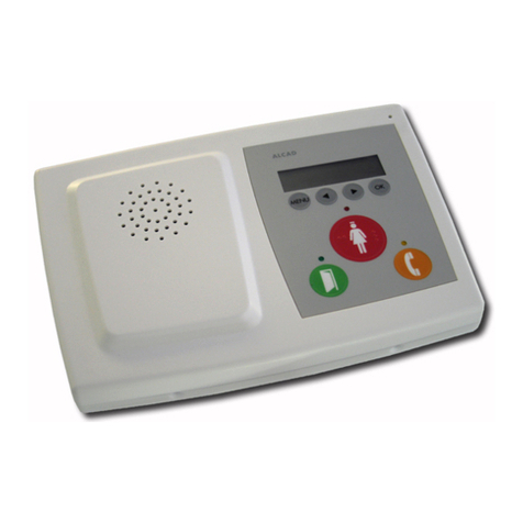
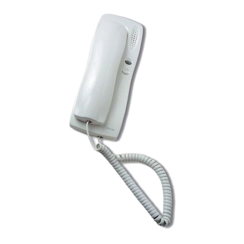
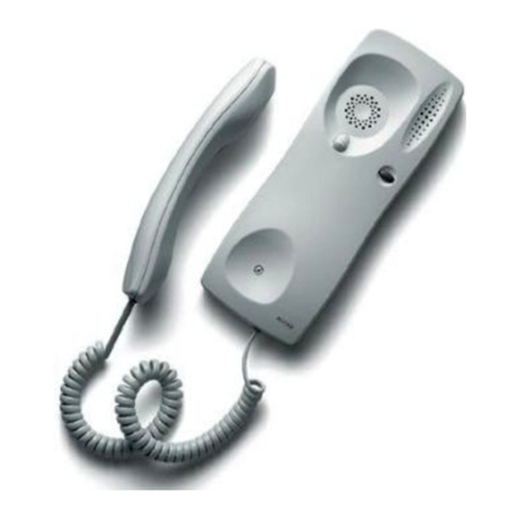
Alcad GRF-202 User manual

KITS SISTEMA DE INTERCOMUNICACIÓN
KITS SYSTEM WITH INTERNAL COMMUNICATION
KITS SYSTÈME AVEC INTERCOMMUNICATION
PORTERO ELECTRÓNICO - DOOR ENTRY SYSTEMS - PORTIER ÉLECTRONIQUE
ÍNDICE
ELEMENTOS Y DIMENSIONES ..................................................................................................................................................2
FUNCIONAMIENTO GENERAL DEL SISTEMA DE INTERCOMUNICACIÓN...................................................................................3
INSTALACIÓN BÁSICA EN VIVIENDA UNIFAMILIAR...................................................................................................................5
INSTALACIÓN BÁSICA EN VIVIENDA BIFAMILIAR. INTERCOMUNICACIÓN ENTRE VIVIENDAS...................................................7
INSTALACIÓN EN VIVIENDA BIFAMILIAR. INTERCOMUNICACIÓN EN CADA VIVIENDA (KIT + 2 TELÉFONOS ...........................9
INSTALACIÓN DE ELEMENTOS ADICIONALES.........................................................................................................................11
INSTRUCCIONES DE INSTALACIÓN ........................................................................................................................................12
INSTRUCCIONES DE AJUSTE...................................................................................................................................................17
CARACTERÍSTICAS TÉCNICAS.................................................................................................................................................18
VERIFICACIÓN DE LA INSTALACIÓN.......................................................................................................................................20
INDEX
ELEMENTS AND DIMENSIONS..................................................................................................................................................2
GENERAL OPERATION OF THE DOOR ENTRY SYSTEM WITH INTERNAL COMMUNICATION.......................................................3
STANDARD INSTALLATION IN DETACHED HOUSE.....................................................................................................................5
STANDARD INSTALLATION IN SEMI-DETACHED HOUSE. INTERNAL COMMUNICATION BETWEEN DWELLINGS .........................7
INSTALLATION IN SEMI-DETACHED HOUSE. INTERNAL COMMUNICATION IN EACH DWELLING (KIT + 2 TELEPHONES).............
INSTALLATION OF ADDITIONAL ELEMENTS.............................................................................................................................11
INSTALLING INSTRUCTIONS ...................................................................................................................................................12
ADJUSTMENT INSTRUCTIONS.................................................................................................................................................17
TECHNICAL CHARACTERISTICS...............................................................................................................................................18
TROUBLE SHOOTING .............................................................................................................................................................21
SOMMAIRE
ELÉMENTS ET MESURES............................................................................................................................................................2
FONCTIONNEMENT GÉNÉRAL DU SYSTÈME DE PORTIER AVEC INTERCOMMUNICATION ........................................................3
INSTALLATION BASIQUE EN LOGEMENT MONO-FAMILIAL .......................................................................................................5
INSTALLATION BASIQUE EN LOGEMENT BI-FAMILLE. INTERCOMMUNICATION ENTRE LOGEMENTS..........................................7
INSTALLATION DANS UN LOGEMENT BI-FAMILLE. INTERCOMMUNICATION DANS CHAQUE LOGEMENT (KIT+2 TÉLÉPHONES ......9
INSTALLATION DÉLÉMENTS ADDITIONNELS............................................................................................................................11
INSTRUCTIONS D'INSTALLATION ............................................................................................................................................12
INSTRUCTION DE RÉGLAGE ...................................................................................................................................................17
CARACTÉRISTIQUES TECHNIQUES..........................................................................................................................................18
VERIFICATION DE LINSTALLATION..........................................................................................................................................22
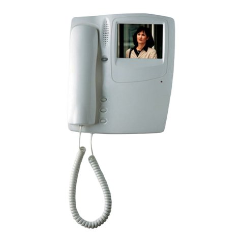
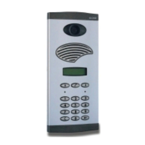
GRF-202 TIN-022 TIN-024 ALA-020
PLACA DE CALLE
ENTRANCE PANEL
PLAQUE DE RUE TELÉFONO
TELEPHONE
TÉLÉPHONE
PORTERO ELECTRÓNICO - DOOR ENTRY SYSTEMS - PORTIER ÉLECTRONIQUE
ARRIBA
UP
HAUT
45 mm
114 mm
131 mm
2
ELEMENTOS Y DIMENSIONES
ELEMENTS AND DIMENSIONS
ELÉMENTS ET MESURES
Placa de calle
Entrance panel
Plaque de rue
Caja de empotrar. 1, 2 alturas.
Flush-mounted box. 1, 2 storeys.
Boîtier encastrable. 1, 2 étages.
Caja de superficie. 1, 2 alturas.
Surface box. 1, 2 storeys.
Boîtier saillie. 1, 2 étages.
O
OR
OU
O
OR
OU
PLACA DE CALLE - ENTRANCE PANEL - PLAQUE DE RUE
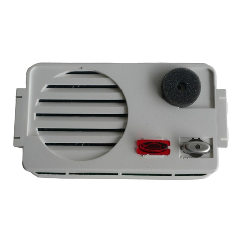
Grupo fónico
Audio unit
Groupe phonique
9610041
GRF-202
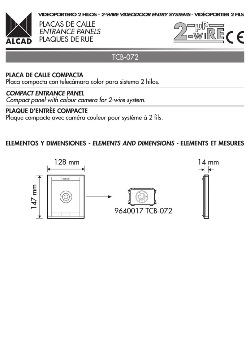
128 mm
147 mm
12 mm 128 mm
147 mm
40 mm
MÓDULOS INTERIORES - INSIDE MODULES - MODULES INTERIEURS
106 mm
90 mm
60 mm
230 V230 V V
Alimentador
Power supply
Alimentation
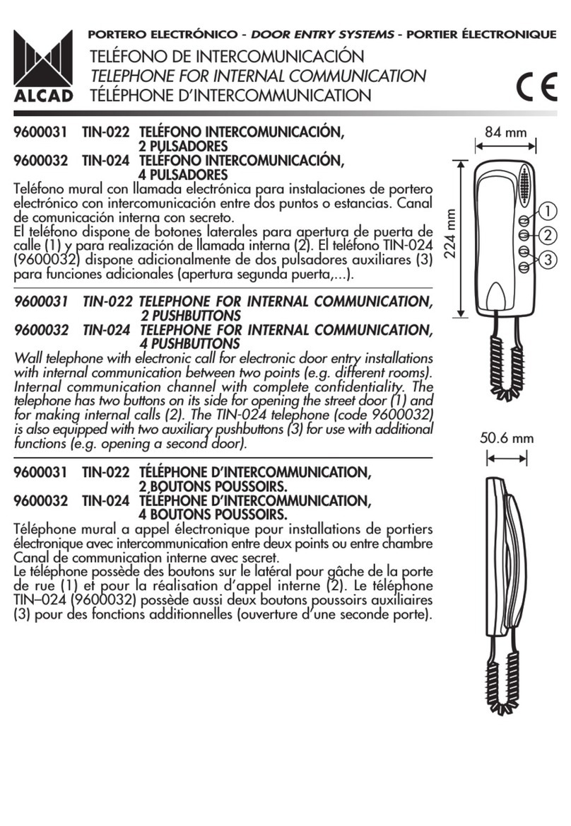
84 mm 50,6 mm
224 mm
84 mm 50,6 mm
224 mm
Teléfono de intercomunicación
Telephone for internal communication
Téléphone d'intercommunication

PORTERO ELECTRÓNICO - DOOR ENTRY SYSTEMS - PORTIER ÉLECTRONIQUE
FUNCIONAMIENTO GENERAL DEL SISTEMA DE INTERCOMUNICACIÓN
GENERAL OPERATION OF THE DOOR ENTRY SYSTEM WITH INTERNAL COMMUNICATION
FONCTIONNEMENT GÉNÉRAL DU SYSTÈME DE PORTIER AVEC INTERCOMMUNICATION
3
REALI AR DESDE UN TELÉFONO UNA LLAMADA A OTRO TELÉFONO
MAKING A CALL FROM ONE TELEPHONE TO ANOTHER
EFFECTUER UN APPEL À UN AUTRE TÉLÉPHONE
Para llamar a otro teléfono, descuelgue el auricular y pulse el segundo botón del teléfono.
To call another telephone, pick up the receiver and press the second button on the telephone.
Pour appeler un autre téléphone, décrochez le combiné et appuyer le deuxième bouton du téléphone.
REALI AR UNA LLAMADA A UNA VIVIENDA DESDE LA PLACA DE CALLE
MAKING A CALL TO A DWELLING FROM THE ENTRANCE PANEL
RÉALISER UN APPEL À UN LOGEMENT DEPUIS LA PLAQUE DE RUE
Presione el pulsador correspondiente de la placa de calle. La placa emitirá unos tonos de confirmación de llamada.
Press the appropriate pushbutton on the entrance panel. The panel will emit several tones confirming that the call is being made.
Appuyer le bouton correspondant de la plaque de rue. La plaque émettra une tonalité de confirmation dappel.
Confirmación de llamada
Confirmation of the call
Confirmation de l'appel

PORTERO ELECTRÓNICO - DOOR ENTRY SYSTEMS - PORTIER ÉLECTRONIQUE
4
RECIBIR EN EL TELÉFONO UNA LLAMADA DE LA PLACA DE CALLE DURANTE LA COMUNICACIÓN CON OTRO TELÉFONO
RECEIVING A CALL FROM THE ENTRANCE PANEL TO A TELEPHONE WHICH IS COMMUNICATING WITH ANOTHER TELEPHONE
VOUS RECEVE UN APPEL DE LA PLAQUE DE RUE PENDANT LA COMMUNICATION AVEC UN AUTRE TÉLÉPHONE
Si el teléfono de la vivienda solicitada está en comunicación con otro teléfono, el auricular del teléfono emitirá unos tonos de aviso;
dándole la opción de ponerse en comunicación con el visitante o de continuar con la comunicación con el otro teléfono.
If the telephone in the dwelling being called from the entrance panel is already communicating with another telephone, its receiver
will emit several warning tones, allowing you to choose whether to speak to the visitor or to continue communicating with the other
telephone.
Si le téléphone du logement demandé est en communication avec un autre téléphone, le combiné émettra des tonalités, en offrant la
possibilité de prendre contact avec le visiteur ou de continuer la communication ne cours.
PONER AL VISITANTE EN COMUNICACIÓN CON OTRO TELÉFONO
PUTTING THE VISITOR THROUGH TO ANOTHER TELEPHONE
METTRE EN COMMUNICATION AVEC UN AUTRE TÉLÉPHONE LE VISITEUR
Estando en comunicación con el visitante desde uno de los teléfonos, es posible poner a éste en comunicación con otro teléfono.
While communicating with the visitor on one telephone, it is possible to transfer the call to another telephone.
Tous en étant en communication avec le visiteur d'un des téléphones, il est possible de mettre celui-ci en communication avec un autre
téléphone
Confirmación de llamada
Confirmation of the call
Confirmation de l'appel
Llamar al otro teléfono
Calling to the other telephone
Appel a l'autre téléphone
Confirmación de llamada
Confirmation of the call
Confirmation de l'appel
Tonos de aviso
Warning tones
Tonalités
Pulsar y soltar
Press and release
Appuyez et lâchez
Establecer comunicación con el visitante
Establishing communication with the person who is calling
Prendre contact avec le visiteur
Colgar auricular
Hang up the receiver
Raccrocher l'écouteur
Teléfono 1
Telephone 1
Téléphone 1
Teléfono 2
Telephone 2
Téléphone 2
Teléfono 1
Telephone 1
Téléphone 1
Teléfono 2
Telephone 2
Téléphone 2
Teléfono 1
Telephone 1
Téléphone 1
Teléfono 2
Telephone 2
Téléphone 2
Placa de calle
Entrance panel
Plaque de rue

(2 Máx. 12 Vac, 800 mA
(1 Utilice manguera independiente
Use separate cable hose
Utiliser une gaine indépendante
V
2
230 V
ALA-020
(230 V
2
Abrepuertas AC (No incluído
Electric lock AC (Not included)
Gâche AC (Non inclus (2
7
2
INTERCOMUNICACIÓN
Recibida una llamada realizada desde el otro teléfono, el teléfono emitirá un aviso sonoro. Al descolgar el auricular, se establecerá
la comunicación entre los dos teléfonos.
PLACA DE CALLE
Presionado el pulsador de la placa, los dos teléfonos emitirán un aviso sonoro. Al descolgar el auricular de uno de los teléfonos, se
establecerá la comunicación con la placa de calle. Posibilidad de poner al visitante en comunicación con el otro teléfono (consulte
página 4 .
Si los teléfonos se encuentran en comunicación interna, es posible responder la llamada o continuar con la comunicación interna
(consulte página 4 .
PORTERO ELECTRÓNICO - DOOR ENTRY SYSTEMS - PORTIER ÉLECTRONIQUE
INTERNAL COMMUNICATION
When a call made from another telephone is received, the receiving telephone will emit a warning sound. On picking up the receiver,
communication will be established between the two telephones.
ENTRANCE PANEL
When the entrance panel pushbutton is pressed, both telephone will emit a warning sound. When the receiver of one of the telephones
is picked up, communication is established with the entrance panel. It is possible to transfer the visitors call to the other telephone (see
page 4).
If the telephones are communicating internally, it is possible to either answer the call or to continue communicating internally (see page
4).
INTERCOMMUNICATION
Reçu un appel réalisé dun autre téléphone, le téléphone émettra une sonnerie, en décrochant le combiné, la communication sera établie
entre les deux téléphones.
PLAQUE DE RUE
En appuyant le bouton poussoir de la plaque, les deux téléphones émettront une sonnerie. En décrochant le combiné dun des téléphones,
la communication sétablira avec la plaque de rue. Possibilité de mettre en communication le visiteur avec lautre téléphone ( Voir page
4.
Si les téléphones se trouvent en communication interne, il est possible de répondre à lappel ou de continuer avec la communication
interne (voir page 4 .
5
ESQUEMA UNIFILAR - SINGLE-WIRED DIAGRAM - SCHÉMA À UN FIL
INSTALACIÓN BÁSICA EN VIVIENDA UNIFAMILIAR
STANDARD INSTALLATION IN DETACHED HOUSE
INSTALLATION BASIQUE EN LOGEMENT MONO-FAMILIAL
TABLA DE SECCIONES
SECTION TABLE
TABLEAU DE SECTIONS
0,25 mm20,6 mm 22
1,1 mm 17
0,8 mm 20
0,5 mm2
1 mm 2
Hasta 50 m - Up to 50 m - Jusqu'à 50 m
Hasta 25 m - Up to 25 m - Jusqu'à 25 m
Hasta 100 m - Up to 100 m - Jusqu'à 100 m
AWG
TIN-022
TIN-024
7
TIN-022
TIN-024
Funcionamiento - Operatio - Fonctionnement
(1

230 V
V
~
ALA-020
GRF-202
cod. 9610041
1 2 3 4 5 +i Pi i i
Abrepuertas AC (No incluído
Electric lock AC (Not included)
Gâche AC (Non inclus
PORTERO ELECTRÓNICO - DOOR ENTRY SYSTEMS - PORTIER ÉLECTRONIQUE
71
234
6
ESQUEMA DE CABLEADO - WIRED DIAGRAM - SCHÉMA DE CABLAGE
(1 Utilice manguera independiente.
Use separate cable hose.
Utiliser une gaine indépendante.
230 V
TIN-022
TIN-024 TIN-022
TIN-024
(1
GRF-202
21
910 12+i11
V~
1 2 3 4 5 +i Pi i i
21Pi

(2 Máx. 12 Vac, 800 mA
(1 Utilice manguera independiente
Use separate cable hose
Utiliser une gaine indépendante
V
2
230 V
ALA-020
(230 V
2
(2
7
2
7
Abrepuertas AC (No incluído
Electric lock AC (Not included)
Gâche AC (Non inclus
INTERCOMUNICACIÓN
Recibida una llamada realizada desde el teléfono de la otra vivienda, el teléfono emitirá un aviso sonoro. Al descolgar el auricular,
se establecerá la comunicación entre los dos teléfonos.
PLACA DE CALLE
El teléfono asociado al pulsador de la placa, emitirá un aviso sonoro. Al descolgar el auricular del teléfono, se establecerá la comunicación
con la placa de calle. Posibilidad de poner al visitante en comunicación con el teléfono de la otra vivienda (consulte página 4 .
Si el teléfono solicitado se encuentra en comunicación interna con el teléfono de la otra vivienda, es posible responder la llamada o
continuar con la comunicación interna (consulte página 4 .
PORTERO ELECTRÓNICO - DOOR ENTRY SYSTEMS - PORTIER ÉLECTRONIQUE
INTERNAL COMMUNICATION
When a call made from the telephone of the other dwelling is received, the receiving telephone will emit a warning sound. On picking
up the receiver, communication will be established between the two telephones.
ENTRANCE PANEL
The telephone associated to the pushbutton pressed on the entrance panel will emit a warning sound. When its receiver is picked up,
communication will be established with the entrance panel. It is possible to transfer the visitors call to the telephone of the other dwelling.
(see page 4).
If the telephone being called is communicating internally with the telephone of the other dwelling, it is possible to either answer the
call or to continue communicating internally (see page 4).
INTERCOMMUNICATION
Reçu un appel réalisé depuis un téléphone dun autre logement, le téléphone émettra une sonnerie. En décrochant le combiné, la
communication sétablira entre les deux téléphones.
PLAQUE DE RUE
Le téléphone associé au bouton poussoir de la plaque, émettra une sonnerie. En décrochant le combiné du téléphone, la communication
se fera avec la plaque de rue. Possibilité de mettre le visiteur en communication avec le téléphone de lautre logement (voir page 4
Si le téléphone appelé est déjà en communication interne avec un autre téléphone dun autre logement, il est possible de répondre à
lappel ou de continuer la communication interne (voir page 4 .
7
ESQUEMA UNIFILAR - SINGLE-WIRED DIAGRAM - SCHÉMA À UN FIL
INSTALACIÓN BÁSICA EN VIVIENDA BIFAMILIAR. INTERCOMUNICACIÓN ENTRE VIVIENDAS
STANDARD INSTALLATION IN SEMI-DETACHED HOUSE. INTERNAL COMMUNICATION
BETWEEN DWELLINGS
INSTALLATION BASIQUE EN LOGEMENT BI-FAMILLE. INTERCOMMUNICATION ENTRE
LOGEMENTS
TABLA DE SECCIONES
SECTION TABLE
TABLEAU DE SECTIONS
0,25 mm20,6 mm 22
1,1 mm 17
0,8 mm 20
0,5 mm2
1 mm 2
Hasta 50 m - Up to 50 m - Jusqu'à 50 m
Hasta 25 m - Up to 25 m - Jusqu'à 25 m
Hasta 100 m - Up to 100 m - Jusqu'à 100 m
AWG
9
TIN-022
TIN-024
Vivienda 1
Dwelling 1
Logement 1
TIN-022
TIN-024
Vivienda 2
Dwelling 2
Logement 2
Funcionamiento - Operatio - Fonctionnement
(1

230 V
V
~
ALA-020
GRF-202
cod. 9610041
Abrepuertas AC (No incluído
Electric lock AC (Not included)
Gâche AC (Non inclus
PORTERO ELECTRÓNICO - DOOR ENTRY SYSTEMS - PORTIER ÉLECTRONIQUE
71
234
8
ESQUEMA DE CABLEADO - WIRED DIAGRAM - SCHÉMA DE CABLAGE
(1 Utilice manguera independiente.
Use separate cable hose.
Utiliser une gaine indépendante.
230 V
TIN-022
TIN-024
Vivienda 2
Dwelling 2
Logement 2
TIN-022
TIN-024
Vivienda 1
Dwelling 1
Logement 1
(1
GRF-202
1 2 3 4 5 +i Pi i i
21
910 12+i11
V~
21 Pi
1 2 3 4 5 +i Pi i i
12

V
2
230 V
ALA-020
(230 V
2
(2
7
2
7 7
2
7
(2 Máx. 12 Vac, 800 mA
(1 Utilice manguera independiente
Use separate cable hose
Utiliser une gaine indépendante
Abrepuertas AC (No incluído
Electric lock AC (Not included)
Gâche AC (Non inclus
INTERCOMUNICACIÓN
Es posible en cada vivienda la intercomunicación entre los dos teléfonos de dicha vivienda. Recibida una llamada realizada desde el
otro teléfono, el teléfono emitirá un aviso sonoro. Al descolgar el auricular, se establecerá la comunicación entre los dos teléfonos.
PLACA DE CALLE
Los teléfonos asociados al pulsador de la placa presionado, emitirán un aviso sonoro. Al descolgar el auricular de uno de los teléfonos,
se establecerá la comunicación con la placa de calle. Posibilidad de poner al visitante en comunicación con el otro teléfono (consulte
página 4 .
Si los teléfonos se encuentran en comunicación interna, es posible responder la llamada o continuar con la comunicación interna
(consulte página 4 .
PORTERO ELECTRÓNICO - DOOR ENTRY SYSTEMS - PORTIER ÉLECTRONIQUE
INTERNAL COMMUNICATION
It is possible to have internal intercommunication between the two telephones of each dwelling. When a call made from the other
telephone of the same dwelling is received, the receiving telephone will emit a warning sound. When the receiver is picked up,
communication is established between the two telephones.
ENTRANCE PANEL
The telephones associated to the pushbutton pressed on the entrance panel will emit a warning sound. When its receiver of one of the
telephones in the dwelling is picked up, communication will be established with the entrance panel. It is possible to transfer the visitors
call to the other telephone in the same dwelling (see page 4).
If the telephones being called are communicating internally, it is possible to either answer the call or to continue communicating internally
(see page 4).
INTERCOMMUNICATION
Lintercommunication est possible entre les deux téléphones de chaque logement. Reçu un appel dun autre téléphone du même logement,
le téléphone émettra une sonnerie. En décrochant le combiné, la communication sétablira entre les deux téléphones.
PLAQUE DE RUE
Les téléphones associés au bouton poussoir de la plaque appuyés, ils émettront une tonalité. En décrochant le combiné dun des
téléphones du logement, la communication avec la plaque de rue sera établie. Possibilité de mettre le visiteur en communication avec
lautre téléphone du même logement (voir page 4
Si les téléphones sont en communication interne, il est possible de répondre à lappel ou de poursuivre la communication interne (voir
page 4 .
9
ESQUEMA UNIFILAR - SINGLE-WIRED DIAGRAM - SCHÉMA À UN FIL
INSTALACIÓN EN VIVIENDA BIFAMILIAR. INTERCOMUNICACIÓN EN CADA VIVIENDA
(KIT + 2 TELÉFONOS).
INSTALLATION IN SEMI-DETACHED HOUSE. INTERNAL COMMUNICATION IN EACH DWELLING
(KIT + 2 TELEPHONES)
INSTALLATION DANS UN LOGEMENT BI-FAMILLE. INTERCOMMUNICATION DANS CHAQUE
LOGEMENT (KIT+2 TÉLÉPHONES)
TABLA DE SECCIONES
SECTION TABLE
TABLEAU DE SECTIONS
0,25 mm20,6 mm 22
1,1 mm 17
0,8 mm 20
0,5 mm2
1 mm 2
Hasta 50 m - Up to 50 m - Jusqu'à 50 m
Hasta 25 m - Up to 25 m - Jusqu'à 25 m
Hasta 100 m - Up to 100 m - Jusqu'à 100 m
AWG
9
TIN-022
TIN-024 TIN-022
TIN-024 TIN-022
TIN-024 TIN-022
TIN-024
Vivienda 1
Dwelling 1
Logement 1
Vivienda 2
Dwelling 2
Logement 2
Funcionamiento - Operatio - Fonctionnement
(1

230 V
V
~
ALA-020
GRF-202
cod. 9610041
1 2 3 4 5 +i Pi i i 12345+i Pi i i
Abrepuertas AC (No incluído
Electric lock AC (Not included)
Gâche AC (Non inclus
PORTERO ELECTRÓNICO - DOOR ENTRY SYSTEMS - PORTIER ÉLECTRONIQUE
71
234
ESQUEMA DE CABLEADO - WIRED DIAGRAM - SCHÉMA DE CABLAGE
10
(1 Utilice manguera independiente.
Use separate cable hose.
Utiliser une gaine indépendante.
230 V
TIN-022
TIN-024 TIN-022
TIN-024
Vivienda 1
Dwelling 1
Logement 1
Vivienda 2
Dwelling 2
Logement 2
(1
GRF-202
21
910 12+i11
V~
21 Pi
1 2 3 4 5 +i Pi i i
12
12345+i Pi i i

2
2
PORTERO ELECTRÓNICO - DOOR ENTRY SYSTEMS - PORTIER ÉLECTRONIQUE
PULSADOR AUXILIAR 1
AUXILIARY PUSH-BUTTON 1
BOUTON AUXILIAIRE 1
Activación
Activatio
Activation
Conexión
Co ectio
Connexion
Accesorio
Accessory
Accesoire
3
4 5 +i Pi
26
27
28
29
i i
TIN-024
PULSADOR AUXILIAR 2
AUXILIARY PUSH-BUTTON 2
BOUTON AUXILIAIRE 2
Activación
Activatio
Activation
Conexión
Co ectio
Connexion
Accesorio
Accessory
Accesoire
3
4 5 +i Pi
26
27
28
29
i i
TIN-024
2
CONEXIÓN PULSADORES AUXILIARES (TELÉFONO TIN-024)
CONNECTION OF THE AUXILIARY PUSH-BUTTONS (TELEPHONE TIN-024)
CONNEXION DES BOUTONS AUXILIAIRES (TÉLÉPHONE TIN-024)
INSTALACIÓN DE ELEMENTOS ADICIONALES
INSTALLATION OF ADDITIONAL ELEMENTS
INSTALLATION DÉLÉMENTS ADDITIONNELS
Las bornas 26, 27 y 28, 29 son contactos libres de potencial. A la hora de utilizarlas tenga en cuenta las siguientes limitaciones de
conexión: 50 mA - 12 Vdc.
Terminals number 26, 27 and 28, 2 are potential-free contacts. To use them, take into account the following connection limitations:
50 mA - 12 Vdc.
Les bornes 26, 27 et 28, 29 sont des contactes libre de potentiel. Pour les employer, tenez compte des limitations de connexion suivants:
50 mA - 12 Vdc.
Pulsador
Push-button
Boutton-poussoir
Pulsador
Push-button
Boutton-poussoir
11
APERTURA DE PUERTA DESDE EL INTERIOR
DOOR OPENING FROM INSIDE
OUVERTURE DE PORTE DEPUIS L'INTÉRIEUR
230 V
GRF-202
cod. 9610041
GRF-202
11910 12 71
234
+i
V~
21
21 Pi

1Rompa los tabiques que necesite para permitir el
paso de los cables. Dispone de dos aberturas
posteriores.
Break the perforated openings needed to pass the
cables through.There are two openings at the
back.
Casser les opercules pour permettre le passage
des câbles. Il possède deux ouvertures postérieures.
PORTERO ELECTRÓNICO - DOOR ENTRY SYSTEMS - PORTIER ÉLECTRONIQUE
12
INSTRUCCIONES DE INSTALACIÓN
INSTALLING INSTRUCTIONS
INSTRUCTIONS D'INSTALLATION
RECOMENDACIONES - RECOMMENDATIONS - RECOMMANDATIONS
A la hora de colocar la placa de calle, asegúrese que ni los rayos del sol ni fuentes de luz intensa incidan directamente sobre la
telecámara, evitando así efectos no deseados en la visualización de la imagen (efecto contraluz y manteniendo la vida útil del equipo.
When installing the entrance panel make sure that the sunrays or intense light sources do not fall directly on the video unit, avoiding
nonwhished effects in picture display (backlight effect) and same way keeping the operational life of the equipment.
Lorsque vous installerez la plaque de rue, assurez-vous bien que les rayons solaires ou une autre source de lumière intense ne coïncide
pas directement sur la caméra, vous evíterez ainsi les problémes de visualisation (effet contre jour,... et préserverait la vie du matériel.
CAJA DE EMPOTRAR
FLUSH MOUNTED BOX
BOÎTIER ENCASTRABLE
Rompa el tabique de las aberturas que requiera
para pasar los cables.
Break off the perforated holes that you need to
pass the cables through.
Cassez la cloison des ouvertures nécessaires pour
faire passer les câbles.
1Coloque la caja de empotrar de modo que la
parte superior quede a una altura de 1,7 m.
Place the flush-mounted box in position so that the
top is 1.7 m. high.
Placez le boîtier encastrable de telle sorte que la
partie supérieure soit placée à une hauteur de 1,7
m.
2
1,7 m
CAJA DE SUPERFICIE
SURFACE BOX
BOÎTIER SAILLIE
Coloque la caja de superficie de modo que la
parte superior quede a una altura de 1,7 m.
Place the surface box in position so that the top
is 1.7 m. high.
Placez le boîtier saillie de telle sorte que la partie
supérieure soit placée à une hauteur de 1,7 m.
2
1,7 m

PORTERO ELECTRÓNICO - DOOR ENTRY SYSTEMS - PORTIER ÉLECTRONIQUE
Levante, haciendo palanca, la pestaña del tarjetero
y coloque la etiqueta identificadora de cada
pulsador.
Lever open the cover of the card-holder and insert
the card that identifies the pushbutton
Levez la languette du panneau d'étiquettes en
faisant levier, et placez l'étiquette d'identification
correspondant à chaque bouton-poussoir.
1
PLACA DE CALLE - ENTRANCE PANEL - PLAQUE DE RUE
MONTAJE DE PLACA DE CALLE EN CAJA DE EMPOTRAR
MOUNTING THE ENTRANCE PANEL IN A FLUSH-MOUNTED BOX
MONTAGE DE LA PLAQUE DE RUE DANS UN BOÎTIER ENCASTRABLE
Place the rings of the panel over the extracted
fixing pins. The unused pins should be placed in
their slots.
Introduzca las anillas de la placa sobre los bisagras.
Introduzca completamente en sus ranuras las
bisagras no utilizadas.
Introduisez les anneaux de la plaque sur les axes
de fixation retirés. Introduisez complètement dans
leurs rainures les axes non utilisés.
2
Extraiga los tapones y las bisagras de la caja de
empotrar. Extraiga las dos bisagras que requiera
según quiera abrir la placa hacia la derecha, la
izquierda o hacia abajo.
Remove the caps and the fixing pins from the flush-
mounted box. Choose the two fixing pins you want
to hinge the panel on to, so that it opens either to
the right or to the left or downwards.
Retirez les bouchons et les axes de fixation du
boîtier encastrable. Enlevez les deux axes requis
suivant si vous voulez ouvrir la plaque vers la
droite, vers la gauche ou bien vers le bas.
1
13

PORTERO ELECTRÓNICO - DOOR ENTRY SYSTEMS - PORTIER ÉLECTRONIQUE
Realice las conexiones eléctricas. Consulte los
esquemas de cableado.
3
Make the electrical connections. See wired
diagrams.
Réalisez les connexions électriques. Voir schémas
de cablage.
Realizada la conexión del resto de componentes
de la instalación, podrá realizar una llamada.
Realice entonces el ajuste de la placa de calle.
Consulte página 17.
4
Once the connection of the other components of
the installation have been made, you will be able
to make calls. Now adjust the entrance panel.
See page 17.
Réaliser la connexion et réglage du reste des
composants de linstallation, vous pourrez réaliser
un appel. Fait alors le réglage de la plaque de
rue. Voir page 17.
MONTAJE DE PLACA DE CALLE EN CAJA DE SUPERFICIE
MOUNTING THE ENTRANCE PANEL IN A SURFACE WALL-MOUNTED BOX
MONTAGE DE LA PLAQUE DE RUE EN BOÎTIER DE SURFACE
Realice las conexiones eléctricas. Consulte los
esquemas de cableado.
1
Make the electrical connections. See wired
diagrams.
Réalisez les connexions électriques. Voir schémas
de cablage.
Realizada la conexión del resto de componentes
de la instalación y montados los teléfonos, podrá
realizar una llamada. Realice entonces el ajuste
de la placa de calle. Consulte página 17.
2
Once the connection of the other components of
the installation have been made, you will be able
to make calls. Now adjust the entrance panel.
See page 17.
Réaliser la connexion et réglage du reste des
composants de linstallation, vous pourrez réaliser
un appel. Fait alors le réglage de la plaque de
rue. Voir page 17.
14

PORTERO ELECTRÓNICO - DOOR ENTRY SYSTEMS - PORTIER ÉLECTRONIQUE
ALIMENTADOR - POWER SUPPLY - ALIMENTATION
Montaje en carril DIN.
Mounting on a DIN rail.
Montage sur rail DIN.
2
Realice las conexiones del alimentador con los
elementos que conforman el portero según se
indica en los esquemas de las instrucciones de
conexión.
Connect up the power supply with the elements
that make up the door entry system as shown in
the diagrams in the connection instructions.
Branchez l'alimentation avec les éléments qui
composent le système du portier comme illustré
dans les schémas des instructions de branchement.
4
Coloque el alimentador en un lugar bien ventilado, sin humedad y alejado de fuentes directas de calor. Evite obstruir las ranuras de ventilación
y proteja el alimentador, cumpliendo con la normativa vigente en materia de instalaciones eléctricas (magnetotérmicos, diferenciales... .
Install the power supply unit in a dry, well-ventilated place away from direct sources of heat. Avoid blocking the ventilation slots. Protect
the power supply unit by complying with existing regulations governing electrical installations (avoid high-temperature locations and
strong magnetic fields, ensure correct fusing, etc.).
Installer lalimentation dans un endroit bien aéré, sans humidité et éloigné de sources directes de chaleur. Eviter lobstruction des ouies
de ventilation et protéger lalimentation, en accord avec la norme en matière dinstallation électrique (magnétothermiques, différentiels...
For mounting it on a wall, fix the power supply
with plugs and screws that have been supplied.
Pour le montage sur le mur, fixez l'alimentation
à l'aide des chevilles et vis fournies.
1Para montaje a pared, fije el alimentador con los
tacos y tornillos suministrados.
Si necesita desmontar el alimentador de un carril
DIN, desplace ligeramente la pestaña de sujeción
hacia abajo (1 . Separe la parte inferior del
alimentador del carril DIN (2 .
3
If you need to dismount the power supply unit from
a DIN rail, lightly press the fixing tab downwards
(1). Separate the lower part of the power supply
unit from the DIN rain (2).
Si vous avez besoin de démonter l'alimentation
du rail DIN, déplacer légèrement le clips de fixation
vers le bas (1 Séparer la partie inférieure de
l'alimentation du rail DIN (2 .
15

PORTERO ELECTRÓNICO - DOOR ENTRY SYSTEMS - PORTIER ÉLECTRONIQUE
Disconect the cord
between the telephone
base and the receiver.
Déconnectez le fil entre
la base du téléphone et
le combiné.
1Desconecte el cordón
entre la base del teléfono
y el auricular.
1
2
2Desplace la tapa de la
base del teléfono hacia
la derecha.
Move the cover on the
base of the telephone to
the right.
Déplacez le couvercle de
la base du téléphone vers
la droite.
3Retire la tapa de la base
del teléfono.
Remove the cover from
the base of the telephone.
Enlevez le couvercle de
la base du téléphone.
4Pase los cables de
conexión por la abertura.
Pass the connections
cables through the
opening.
Faites passer les fils de
branchement par
l'ouverture prévue à cet
effet.
5Fije la base a la pared.
Montez la base sur le
mur.
Fix the base to the wall.
6Realice las conexiones
eléctricas.Vea
instrucciones de conexión.
Make the electrical
connections.See
connection instructions.
Faites les branchements
électrique comme indiqué
ci-après.
Corte las aberturas pretroqueladas que necesite
del cubrebornas. Fíjelo al alimentador utilizando
los tornillos de sujeción.
Cassez les trous prédécoupés requis pour le couvre-
borne. Fixez le couvre-borne sur l'alimentation en
utilisant les vis de fixation fournies.
Cut the required perforated openings of the terminal
cover. Fix it to the power supply unit using the
fixing screws.
5
TELÉFONO - TELEPHONE - TÉLÉPHONE
16

PORTERO ELECTRÓNICO - DOOR ENTRY SYSTEMS - PORTIER ÉLECTRONIQUE
1
Ajuste el volumen de audio en la placa de calle y
en los teléfonos (1 .
1
Adjust the volume level on the entrance panel and
on the telephones (1).
Régler le volume du son dans la plaque de rue et
dans les téléphones (1 .
Separe los embellecedores superior e inferior,
aflojando los tornillos de sujeción.
Separate the upper and lower decorative fittings,
by loosening the clamping screws.
Séparez les enjoliveurs supérieur et inférieur, en
dévissant les vis de fixation.
2
3Cierre la placa, presiónela contra la caja de
empotrar o contra la caja de superficie y fíjela a
la misma mediante los tornillos de sujeción.
Close the panel, press it against the flush-mounted
box or against the surface box and fix it to this
using the clamping screws.
Enfoncez-la plaque contre le boîtier encastrable
ou contre le boîtier saillie et fixez-la à ce boîtier
grâce aux vis de fixation.
Ajuste los embellecedores superior e inferior.
Adjust the upper and lower decorative fittings.
Ajustez les enjoliveurs supérieurs et inférieurs.
4
17
PLACA DE CALLE - ENTRANCE PANEL - PLAQUE DE RUE
INSTRUCCIONES DE AJUSTE
ADJUSTMENT INSTRUCTIONS
INSTRUCTIONS DE RÉGLAGE

12 V
Sistema portero - Door e try system - Système de portier
Intercomunicación - I ter al commu icatio - Intercommunication
V
,
12 V
± 10%
0 V18 V
9 V
Audio max. 4 Vpp
5.6 - 6.6 V
0 V
Audio max. 7.0 Vpp
9 V
Tone max. 7.0 Vpp
9 V
9 V 9 V
0 V 9 V
0 V 9 V
9 V
9 V
Tone max. 7.0 Vpp
Tone max. 7.0 Vpp
PORTERO ELECTRÓNICO - DOOR ENTRY SYSTEMS - PORTIER ÉLECTRONIQUE
CARACTERÍSTICAS TÉCNICAS
TECHNICAL CHARACTERISTICS
CARACTÉRISTIQUES TECHNIQUES
PLACA DE CALLE - ENTRANCE PANEL - PLAQUE DE RUE
Nota: Valores de referencia suministrados para la comprobación de los equipos. No utilizar las bornas de los equipos para alimentar
dispositivos adicionales sin consulta previa al fabricante.
Note: Reference values are provided only to enable the checking of equipments and are reliable. Do not use the terminals of the equipments
to feed additional devices without first consulting the manufacturer.
Note: Valeurs de références fournies pour la vérification des équipements et exclusivement. N'utiliser pas les bornes des équipements
pour alimenter des dispositifs supplémentaires sans information préalable du fabricant.
TENSIONES USUALES SEGÚN EL ESTADO DEL EQUIPO
NORMAL VOLTAGES DEPENDING ON THE STATE OF THE EQUIPMENT
TENSIONS USUELLES EN FONCTION DE LÉTAT DE LÉQUIPEMENT
GRUPO FÓNICO GRF-202 - AUDIO UNIT GRF-202 - GROUPE PHONIQUE GRF-202
Alimentación
Power supply
Alimentation
600 mA (max.
Tensión
Voltage
Tension
Corriente
Current
Courant
18
Temperatura de funcionamiento - Operating temperature - Température de travail -10 .. +55 ºC
BORNAS
TERMINALS
BORNES
TRABAJO
WORKING
TRAVAIL
REPOSO
AT REST
VEILLE
21
,
23
,
24
,
27
,
109
,
1211
,
BORNAS
TERMINALS
BORNES
TRABAJO
WORKING
TRAVAIL
REPOSO
AT REST
VEILLE
2+i
,
2Pi1
,
2Pi2
,
21
,
22
,
12 V
0 V
12 V
0 V
i
i

BORNAS
TERMINALS
BORNES
26, 27
TRABAJO
WORKING
TRAVAIL
REPOSO
AT REST
VEILLE
28, 29
0 V18 V
9 V
Audio max. 4 Vpp
5.6 - 6.6 V
0 V
Audio max. 7.0 Vpp
Tone max. 7.0 Vpp
0 V
Sistema portero - Door e try system - Système de portier
Intercomunicación - I ter al commu icatio - Intercommunication
9 V 9 V
9 V
0 V
5 V
0 V 9 V
0 V
0 V 9 V
PORTERO ELECTRÓNICO - DOOR ENTRY SYSTEMS - PORTIER ÉLECTRONIQUE
PULSADORES AUXILIARES (TELÉFONO TIN-024)
AUXILIARY PUSH-BUTTONS (TELEPHONE TIN-024)
BOUTONS AUXILIAIRES (TÉLÉPHONE TIN-024)
ALIMENTADOR ALA-020 - POWER SUPPLY ALA-020 - ALIMENTATION ALA-020
Temperatura de funcionamiento - Operating temperature - Température de travail -10 .. +55 ºC
Alimentación de red
Mains supply
Alimentation de réseau 16 VA
Salida
Output
Sortie
230 V ±10% 50/60 Hz
12 V ±10%
1.2 A (max.
Tensión
Voltage
Tension
Potencia
Power
Puissance
Tensión
Voltage
Tension
Corriente
Current
Courant
TELÉFONO - TELEPHONE - TÉLÉPHONE
19
Temperatura funcionamiento - Operating temperature - Température de travail +5 .. +55 ºC
BORNAS
TERMINALS
BORNES
TRABAJO
WORKING
TRAVAIL
REPOSO
AT REST
VEILLE
2+i
,
2Pi
,
BORNAS
TERMINALS
BORNES
TRABAJO
WORKING
TRAVAIL
REPOSO
AT REST
VEILLE
21
,
23
,
24
,
25
,
i,2
i,2

PORTERO ELECTRÓNICO - DOOR ENTRY SYSTEMS - PORTIER ÉLECTRONIQUE
20
Verifique las conexiones de los diferentes elementos. Compruebe
las tensiones en las diferentes bornas (consulte Características
técnicas, página 18 .
No funciona nada.
Verifique que la tensión de red en los alimentadores.
Verifique que la tensión entre y
V
del alimentador sea
12 ± 10% Vac
. Compruebe si existe algún cortocircuito y
soluciónelo. Desconecte el alimentador de la red durante
1 minuto y vuelva a conectarlo. Si la avería contínúa,
desconecte todas las bornas de y
V
del alimentador, y
verifique que la tensión entre y
V
sea
12 ± 10% Vac
.
Si no es correcta, el alimentador puede estar averiado.
INTERCOMUNICACIÓN
No se puede realizar llamada interna desde ningún teléfono.
Revise las conexiones +i y Pi del grupo fónico hacia todos
los teléfonos.
Compruebe si existe cortocircuito en las
conexiones +i y 5 de los tel
éfonos y soluciónelo. Revise las
conexiones entre i1, i2 del grupo fónico y los pulsadores.
Si no detecta el fallo, el grupo fónico puede estar averiado.
No se puede realizar llamada interna desde uno de los teléfonos.
Compruebe si existe cortocircuito en las conexiones +i y 5
del teléfono y soluciónelo. Revise las conexiones +i y Pi del
teléfono hacia el grupo fónico. Revise la conexión entre i1
ó i2 del grupo fónico, según sea el caso, y el pulsador. Si
no detecta el fallo, el teléfono puede estar averiado.
No hay audio en el teléfono que ha realizado la llamada.
Revise las conexiones i , i entre los teléfonos. Si no detecta
el fallo, el teléfono puede estar averiado.
El teléfono recibe llamada interna pero al descolgar escucha
placa de calle.
Revise las conexiones +i y Pi del teléfono hacia el grupo
fónico. Revise las conexiones i , i entre los teléfonos. Si
no detecta el fallo, el teléfono puede estar averiado.
El teléfono recibe llamada interna pero al descolgar se escucha
un zumbido.
Compruebe si existe cortocircuito en las conexiones i ,i
del teléfono y soluciónelo. Revise las conexiones i , i entre
los teléfonos. Si no detecta el fallo, uno de los teléfonos
puede estar averiado.
FUNCIONAMIENTO CON LA PLACA DE CALLE
No funciona nada.
Verifique la tensión de red en el alimentador. Verifique que
la tensión entre
y
V
del alimentador sea 12 ± 10% Vac.
Compruebe si existe algún cortocircuito y soluciónelo.
Desconecte el alimentador de la red durante 1 minuto y
vuelva a conectarlo.
Si la avería continua, desconecte todas las bornas de
y
V
del alimentador, y verifique que la tensión entre
y
V
sea 12 ± 10% Vac. Si no es correcta, el alimentador
puede estar averiado.
No se iluminan los tarjeteros.
Verifique que la tensión entre
y
V
del alimentador sea
12 ± 10% Vac. Verifique que la tensión entre 9,10 del
grupo fónico, con el pulsador de iluminación accionado,
sea 12 ± 10% Vac. Compruebe si la lámpara está fundida.
No se ilumina el piloto del pulsador de iluminación.
Verifique que la tensión entre
y
V
del grupo fónico sea
12 ± 10% Vac. Si la tensión es correcta, el grupo fónico
puede estar averiado.
No suena la llamada en ningún teléfono.
Verifique que la tensión entre 7,2 del grupo fónico, sin
accionar el pulsador, sea de 9 ± 10% Vdc. Revise la
conexión entre 7 del grupo fónico y los pulsadores. Revise
la conexión 2 del grupo fónico hacia los teléfonos. Si no
detecta el fallo, el grupo fónico puede estar averiado.
No suena la llamada en un teléfono.
Compruebe si existe cortocircuito en las conexiones +i y 5
del teléfono y soluciónelo. Revise las conexiones 5,2 del
teléfono hacia el grupo fónico. Verifique la conexión del
pulsador en la placa de calle. Si no detecta el fallo, el
teléfono o el pulsador de la placa pueden estar averiados.
No se oye la confirmación de llamada en la placa de calle.
Compruebe que se oyen los teléfonos en la placa de calle.
Compruebe que suena la llamada en los teléfonos. Si no
detecta el fallo, el grupo fónico puede estar averiado.
No se oye ningún teléfono desde la placa de calle.
Revise las conexiones 3,2 y +i, 2 del grupo fónico hacia
todos los teléfonos. Compruebe el regulador de volumen
de la placa. Si no detecta el fallo, el grupo fónico puede
estar averiado.
No se oye un teléfono desde la placa de calle.
Revise las conexiones 3,2 y +i, 2 del teléfono hacia el grupo
fónico. Si no detecta el fallo, el teléfono puede estar averiado.
No se oye la placa de calle en ningún teléfono.
Revise las conexiones 4,2 del grupo fónico hacia todos los
teléfonos. Compruebe el regulador de volumen de los
teléfonos en la placa de calle. Si no detecta el fallo, el
grupo fónico puede estar averiado.
No se oye la placa de calle en un teléfono.
Revise las conexiones 4,2 del teléfono hacia el grupo fónico.
Si no detecta el fallo, el teléfono puede estar averiado.
El sonido se acopla.
Baje el volumen del sonido mediante los reguladores de
volumen del grupo fónico.
No funciona el abrepuertas.
Verifique que la tensión entre 1,2 del grupo fónico, sin
pulsar el botón de abrepuertas del teléfono, sea 18 ± 10%
Vdc. Verifique que la tensión entre 11,12 del grupo fónico,
pulsando el botón de abrepuertas del teléfono, sea 12 ±
10% Vac. Si no detecta el fallo, el abrepuertas puede estar
averiado.
VERIFICACIÓN DE LA INSTALACIÓN
This manual suits for next models
3
Table of contents
Other Alcad Intercom System manuals

Alcad
Alcad GRF-204 User manual

Alcad
Alcad TCB-010 User manual

Alcad
Alcad 973 Series User manual

Alcad
Alcad AAL-200 User manual

Alcad
Alcad 980 Series User manual

Alcad
Alcad KVS-30721 User manual

Alcad
Alcad CHC-041 User manual

Alcad
Alcad GRF-200 User manual

Alcad
Alcad ERLEA PLUS KVS-31221 User manual

Alcad
Alcad GRF-200 User manual

Alcad
Alcad MVC-140 User manual

Alcad
Alcad KVS-56121 User manual

Alcad
Alcad 967 Series User manual

Alcad
Alcad MVB-003 User manual

Alcad
Alcad 980 Series User manual

Alcad
Alcad 980 Series User manual

Alcad
Alcad 9650006 KPD-002 User manual

Alcad
Alcad GRF-201 User manual

Alcad
Alcad USOA User manual

Alcad
Alcad TED-001 User manual