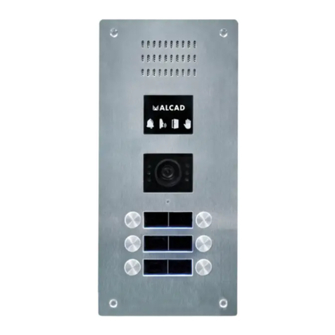
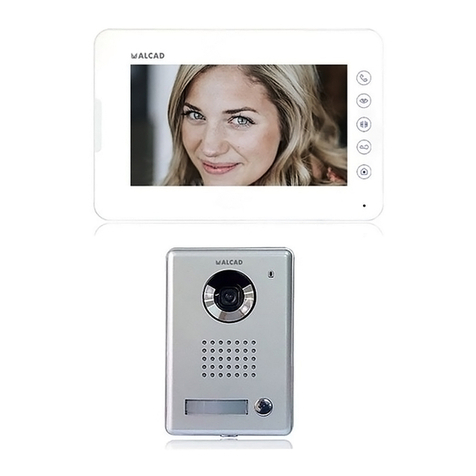
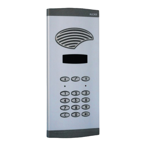
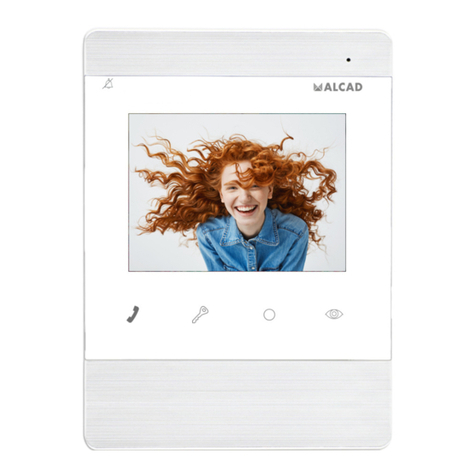
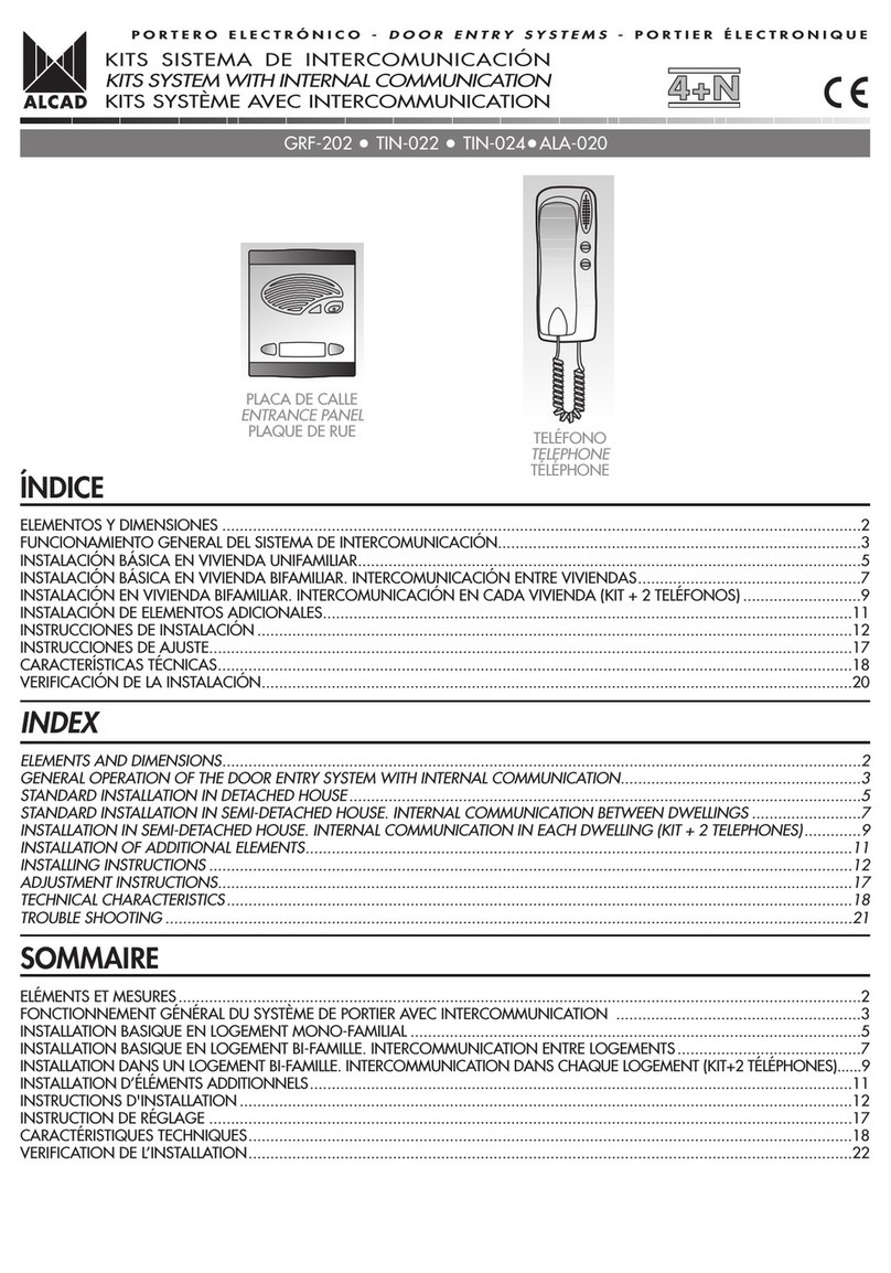
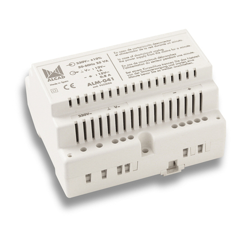
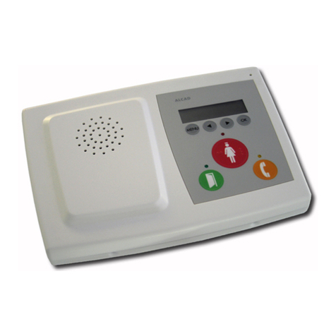
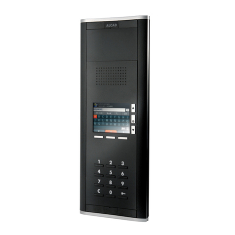
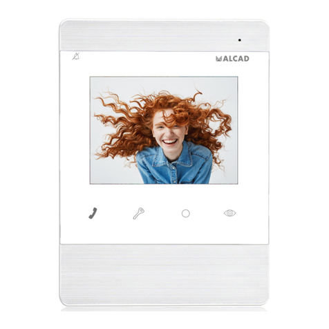
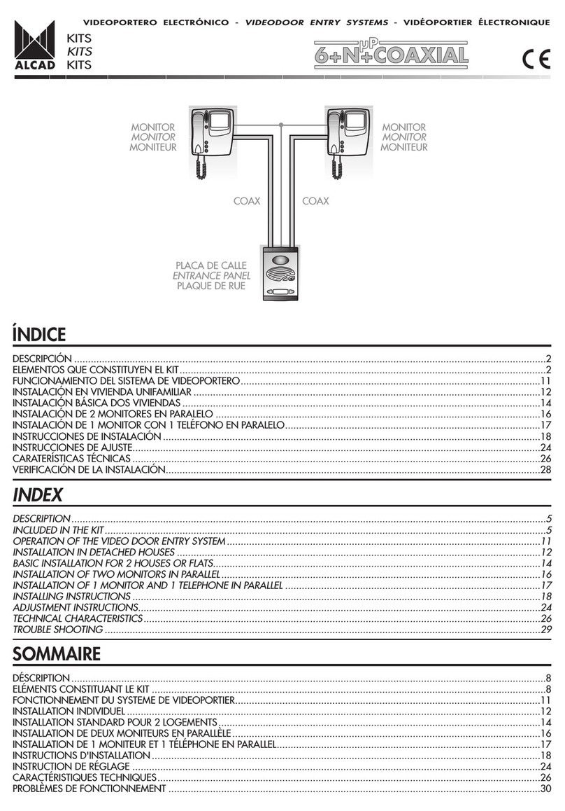
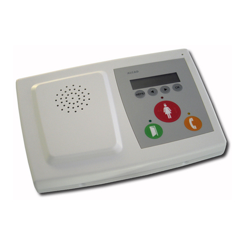
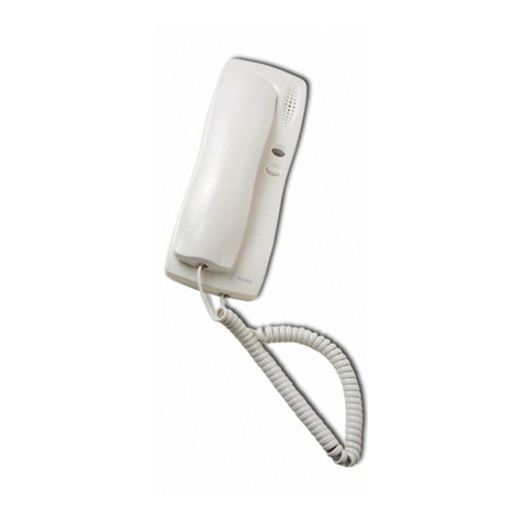
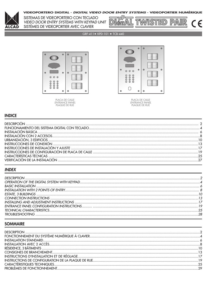
Alcad 201 Series User manual

VIDEO DOOR ENTRY SYSTEM
201
LINE
TECHNICAL MANUAL

2
INDICE
1. ELECTRONIC VIDEO DOOR ENTRY SYSTEM
• Description
• Components
• Video door entry system operation
2. TECHNICAL INFORMATION
• Specifications & Standards
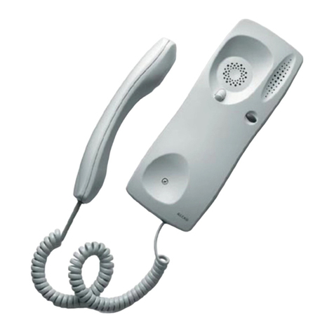
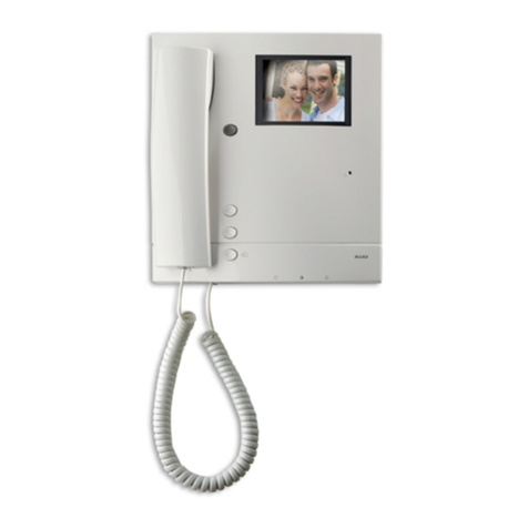
• Monitors
• Telephones
• Tap-offs and splitters
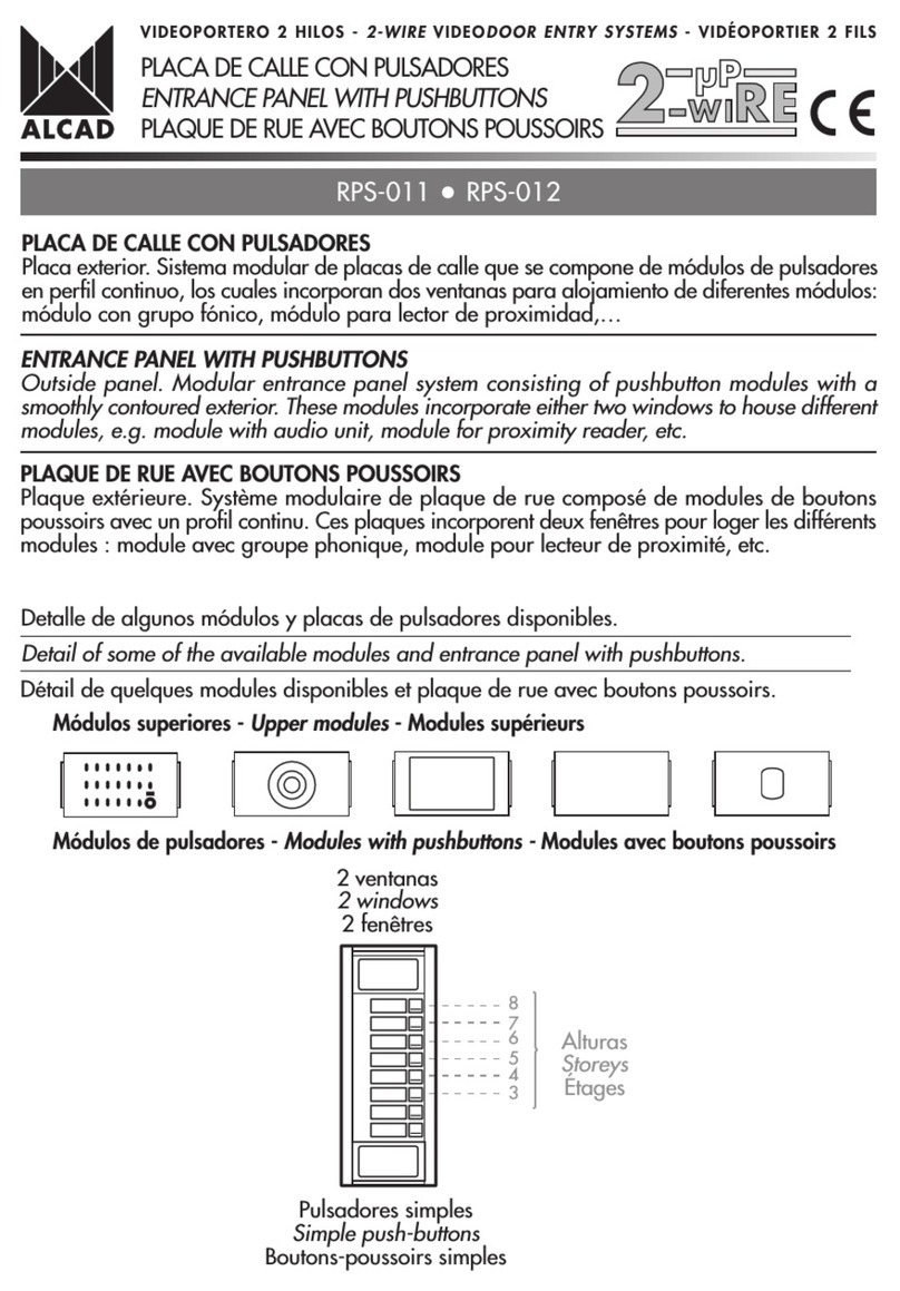
• Entrance panels
- Entrance panel upper modules. External access video unit accessory
- Entrance panel lower modules
• Entrance panels accessories
- Flush-mounted boxes
- Surface wall-mounted boxes
- Rain-shields
- Replacement or cover frames
• Accessories
- Electric lock
- Door contact
• Power supply units
• Kits
3. RANGE OF PANELS
4. MECHANICAL ASSEMBLY
• Flush-mounted box
• Entrance panel
• External access video unit accessory
• Entrance panel accessories
- Surface wall-mounted box
- Rain-shields
- Replacement or cover frames
• Tap-offs and splitters
• Connections bracket
• Monitor
• Telephone
• Power supply units
5. CONNECTIONS AND ADJUSTMENT INSTRUCTIONS
• Entrance panel
- Connections
- Adjustment
• Tap-off
- Connections
• Splitters
- Connections
- Adjustment
• Connections bracket
- Connections
- Adjustment
• Power supply
- Connections
4
5
7
9
9
11
12
13
13
18
20
22
24
26
27
28
28
30
32
36
38
43
43
45
46
47
48
49
51
53
54
56
58
59
59
60
61
63
Pág.

3
6. DIAGRAMS
•General points concerning installations
•Configuration of a video door entry installation
•Video door entry installations
- Standard installation
- Standard installation in distribution
- Installation with two points of entry
- Installation with two points of entry, 1 video and 1 audio
- Installation with three points of entry
- Installation on an estate with several buildings and a single external point of
entry
-Installation on an estate with several buildings and a single external audio point
of entry
- Installation kit - single point of entry
- Installation kit - two houses or flats
•Extending existing installations
- Extending the number of monitors in installations
- Extending the number of telephones in installations
- Door opening from inside a house
7. TROUBLE SHOOTING
•Standard installation
•Installation with several entry points. Installations on estates with several internal buil-
dings
•Kit installations
64
65
69
71
74
77
80
83
88
93
95
97
101
103
104
106
108
Pág.

4
The electronic video door entry system is a direct consequence
of the growing demand for increased measures of security in pre-
sent day housing projects. In addition to being able to listen to the
visitor, as offered by the existing electronic door entry systems on
the market, the visitor can also be identified visually affording gre-
ater control over access to the building.
The microprocessor-based technology that the ALCAD video
door entry system uses allows any installation configuration to be
carried out in the most reliable and comfortable manner.
Standard installations, such as video door entry installations in
buildings with a single point of entry, or more complex installa-
tions, such as installations in buildings with several points of entry
or on estates with one or more general access points are catered
for.
The main elements of a video door entry system are an entran-
ce panel, to be installed at the entry point of the building, and a
monitor in each house or flat.
The entrance panel has a video unit and a series of pushbuttons.
The video unit is the element of the system which captures the
image of the person who is calling. The panel has auxiliary ligh-
ting in order to see the visitor, even in conditions of low external
light. In black and white systems this lighting is by means of infra
red leds (light emitting diodes).The light provided by these leds is
invisible to the human eye which means that visitors can be obser-
ved without them being aware of the fact. The pushbuttons of the
panel allows communication with the different houses or flats.
Each pushbutton corresponds to one house or flat so the number
of pushbuttons will correspond to the number of houses or flats in
the system. When a pushbutton is pressed, a call tone is genera-
ted which sounds on the monitor of the corresponding house or
flat. The monitor comes on at the same time, showing the image of
the person who has called. Communication with the visitor is esta-
blished by simply picking up the handset of the monitor. The moni-
tor has a specific button to allow the visitor access to the property.
When this button is pressed the electric lock installed in the entry
door of the building allows the visitor to enter.
Just as in conventional TV installations, the video door entry
makes use of tap-offs and splitters to distribute the video signal of
the video unit. The tap-offs, normally located on each floor of the
building, allow the video signal to be split to the different monitors
of the installation. The splitters are used when several video
columns or risers are needed.
As any other electronic system, the video door entry system
requires an external power supply in order to work. This function
is carried out by the power supply units which provide the requi-
red voltages for the system from the mains supply. The power
supply units are usually located in a safe place in the hall of the
ground floor or in another common area of the building.
DESCRIPTION
ELECTRONIC VIDEO DOOR ENTRY SYSTEM
1
230 V V
230 V V
ELECTRIC LOCK
POWER SUPPLIES SPLITTER
TAPP-OFF
MONITOR
A
T THE FLAT
ENTRANCE PANEL
PUSH BUTTON
VIDEO UNIT
6+N+COAXIAL SYSTEM
4 Commons + 1 call5
COAXIAL
Number of wires Description
Transmission of the video signal
Power supply of the monitor2
WIRES IN
EACH MONITOR
FIRST FLOOR
LAST FLOOR
230 V
230 V
5
2
COAXIAL
COAXIAL
2
4+N
An entrance panel can be placed on each access point in
installations in buildings with several entry points or on estates
with one or several general entry points and one or several
estate buildings. The control of the different access points is
carried out by the same entrance panels which make up the
video door entry system, which means that the different panels
of the installation must be interconnected.
The video door entry system described in this manual uses
a 6+N+coaxial connection system. The coaxial cable, the
means of transmission of the video signal captured by the
video unit, and two wires for the power supply of the monitors
of the installation, are added to the 4+N connections used by
the electronic door entry systems (4 common wires and 1 inde-
pendent call wire per house or flat). In this way, 7 wires (4
common wires + 1 call wire + 2 wires for the power supply of
the monitor) reach each monitor of the installation as well as
the coaxial cable carrying the video signal.
5
MONITORS
Located in the interior of each house or flat,
the monitor allows the user to receive the call
from the entrance panel, identify the caller,
establish conversation and open the access
door. It includes the auto switch-on function, of
great use in surveillance situations or whene-
ver communication with the entrance panel is
wanted for whatever reason.
The monitor must be accompanied by the
connection bracket for its correct functioning.
TELEPHONES
The system also allows the use of ALCAD
telephones with confidentiality feature in the
interior of each house or flat, which enable
users to receive the call from the entrance
panel, speak with the visitor at the entrance
panel and open the access door.
CONNECTION BRACKETS
Elements on which the connections of the video
door entry system are made in each one of the
different houses or flats. They allow the connec-
tion of the monitor to the installation. One con-
nections bracket is required for each monitor of
the installation.
COMPONENTS
HOUSES OR FLATS
VIDEO DISTRIBUTION
TAP-OFFS
Normally located on each floor of the
building the tap-offs branch the video
input signal to its tap outputs, where they
are connected to the monitors of the hou-
ses or flats. The connection in series of
the tap-offs allows the distribution of the
video signal of the video unit to all the
monitors of the installation.
SPLITTERS
Elements which generate multiple independent
output lines from one video signal input line, main-
taining the same video signal on each one. They
allow the distribution of the video signal on seve-
ral independent columns.

6
ACCESS TO THE BUILDING
ENTRANCE PANEL
Generally installed at the entry point of buildings,
this panel houses the video unit, audio unit and the
push-buttons.
Its dimensions will depend on the number of different
houses or flats in the building where the video door
entry system is to be installed.
It may be necessary to install more than one panel in
accordance with the number of houses or flats.
Flush-mounted or surface wall-mounted boxes are
used to fix the entrance panel in the desired place.
AUDIO UNIT
This is principal module of the electronic video door
entry system. Its electronics control the activation of
the video unit, allow the call to be made to the moni-
tor of the house or flat, and to establish communica-
tion between the house or flat and the entrance panel.
VIDEO UNIT
This is the module which captures the image of the
person calling from the entrance panel. It has auxi-
liary lighting for situations when the external light is
poor. In black and white systems this lighting is by
means of infrared leds. The light provided by these
leds is invisible to the human eye. It is therefore pos-
sible to identify the person who is calling with abso-
lute discretion, even in conditions of poor light.
push-buttons
Elements housed in the entrance panel
which permit the connection to each one
of the houses or flats. The number of push-
buttons will depend on the number of hou-
ses or flats in the installation.
FLUSH-MOUNTED BOX
Element to which the entrance panel is
fixed and which is normally located at the
point of entry to the building. A cavity must
be prepared in the wall so that the box can
be embedded correctly. The dimensions
will depend on the dimensions of the
entrance panel.
SURFACE WALL-MOUNTED BOX
Element to which the entrance panel is
fixed and which is normally located at the
point of entry to the building. It is not
necessary to first prepare the wall as it is
surface wall-mounted. The dimensions will
depend on the dimensions of the entrance
panel.
ELECTRIC LOCK
Electro-mechanical device which allows
the opening of the access door.
POWER SUPPLY
POWER SUPPLY UNITS
Elements which convert the mains electrical voltage to the required voltages for the correct functioning of the
electronic video door entry system.
In electronic video door entry installations it is necessary to feed the entrance panel (audio unit, video unit,
panel lighting, electric lock) as well as the monitors of the houses or flats. Each of these functions is carried out
by means of a power supply unit.
230 V230 V V
230 V230 V V

7
VIDEO DOOR ENTRY SYSTEM OPERATION
The ALCAD video door entry system incorporates the confi-
dentiality feature in both audio and video. The auto switch-on
function is integrated, allowing the observation of the image
captured by the video unit and communication with the entran-
ce panel without having had to first receive a call.
It is possible to install both monitors and telephones with con-
fidentiality feature in the different houses or flats. The system
allows up to 4 devices in parallel, associated to the same call
wire.
Installations of several access points and estates can be
made without the need for audio or video selectors thanks to
the electronics incorporated in the audio and video units. The
audio units incorporate a microprocessor which enables them
to manage the different access points directly.
Two operating modes: system on stand-by and system active.
SYSTEM ON STAND-BY
In this mode, the monitors of the installation are inactive by
default, in such a way that image viewing, communication with
the entrance panel and door opening functions are disabled.
The entrance panels are on stand-by, with the audio system
disabled until a call is made or the auto switch-on system is acti-
vated from a monitor.
= Functions disabled
Flat 1 Other flats
Flat 1
Time limit for auto switch-on function: 30 seconds
= Functions disabled
Turning on the auto switch-on system
SYSTEM ACTIVE
The system changes from stand-by to active when a monitor
activates the auto switch-on or when a call is made from an
entrance panel.
AUTO SWITCH-ON SYSTEM
The auto switch-on system can activate image viewing, com-
munication with entrance panel and door opening functions
without having had to first receive a call from the entrance panel.
Timer:
The monitor remains active for 30 seconds or until the user
replaces the handset.
Characteristics:
When the auto switch-on is activated, the system does not allow
any other monitor to use the auto switch-on function. The call from
the entrance panel takes priority over the auto switch-on. If,
during the time limit of the auto switch-on, a call is made from the
entrance panel to another house, then the auto switch-on time
period finishes automatically, and only the monitor of the house
or flat which has been called remains activated.

8
RECEPTION OF A CALL
When a call is made to a house from the entrance panel the monitor of the corresponding house is activated, allowing the resi-
dent to observe the image of the visitor, establish conversation and open the entry door.
Timer:
There is a limit of 30 seconds in which to answer the call. Once this has elapsed the monitor returns to stand-by mode.
Once the handset has been picked up, the user has 60 seconds for conversation (or until the handset is replaced). The systems
warns of the end of the time limit for conversation by means of a series of bleeps. It is possible to extend this limit either from the
house or flat or from the entrance panel.
Characteristics:
During the time periods for answering the call or for conversation, the system does not permit any other monitor to use the auto
switch-on function. In systems with several entrance panels, the panel from which the call has been made remains active, with the
other panels blocked (inactive panels). This state is indicated to possible callers from the other panels by the flashing of the red light.
Call made to flat 1
Panel 1
Other flats
Flat 1
Extending the time limit for conversation: + 60 seconds
Other panels
Time limit for conversation: 60 seconds or until the handset is replaced
Time limit to answer the call : 30 seconds
= Functions disabled
Call made to flat 1
Panel 1
and after to flat 2 Flat 1 Flat 2
= Functions disabled
1
2
If first one house is called and then another from the same entrance panel, the first call is automatically annulled.

9
The electronic video door entry products detailed in this manual comply with the following Standards:
EN60065 - Audio and Video Apparatus and Analogical Electronic Apparatus Safety Requirements
EN50081-1 –Electromagnetic Compatibility –Generic Emission Standard.
EN50082-1 –Electromagnetic Compatibility - Generic Immunity Standard.
The ALCAD electronic video door entry system products bear the CE mark.
TECHNICAL INFORMATION
2
Specifications & Standards
MONITORS
4
5
6
1
2
3
7
8
5
6
7
Code 9630000
B/W ANALOGIC VIDEO DOOR ENTRY MONITOR
MVB-001
Black and white monitor with a flat 4" CRT screen for wall mounting on a connections bracket. 6+N+coaxial
analogical system with confidentiality of audio and video communication and auto switch-on function.
In the absence of a call or of the activation of the auto switch-on to a different apartment, the monitor remains
inactive.
Electronic call system; once the call is made from the entrance panel, the call warning tone generated by the
audio unit sounds on the loudspeaker of the handset of the monitor. The handset of the monitor incorporates an
electret type microphone and a 16Ωloudspeaker. The monitor incorporates a lock release button (1) auto
switch-on button (2) and two buttons for auxiliary functions (3). The lock release button is located on one side
so that it can be used without having to pick up the handset. The monitor also has a led (4) to indicate the state
of the system, separate brilliance (5) and contrast (6) controls and a switch to turn the screen on or off (7). The
handset cable is a flexible cord with telephone type connectors (8).
Power supply 15 Vdc
Operating temperature +5ºC to +55ºC
197 mm
224 mm
64.3 mm

10
Lock release
Common
Microphone
Loudspeaker
Electronic call
TERMINALS AT REST WORKING
5 V
9 V
0 V
0 V
0 V
5.6 - 6.6 V
9 V
Audio max 4 Vpp
Audio max 7.0 Vpp
Tone max 7 Vpp
Audio ground
1
2
3
4
5
AUDIO
VIDEO
Video signal common
Power supply ground
Video ground
V1
Video signal
Ground
Power supply voltage 15 V
INACTIVE
5 V
0 V
0 V
0 V
M
0 V 1 Vpp ±0,25 (75 Ω)
12 34 5
V1
V1
25
26
27
28
24
M
M
Code 9630002
MONITOR CONNECTIONS BRACKET
SCM-010
Bracket for the wall mounting of the video door
entry monitor. Analogical 6+N+coaxial system with
confidentiality of audio and video communication. It
includes lift type connection terminals to assure correct
connection. It has several fixing points allowing it to
be fixed to a wall or to a standard 60 x 60mm elec-
trical box.
Operating temperature +5 to + 55ºC
193 mm
166 mm
Description of terminals and voltages:

11
TELEPHONES
Lock release
Common
Microphone
Loudspeaker
Electronic call
TERMINALS
Masa
AT REST WORKING
5 V
8 V
0 V
0 V
Audio max 4 Vpp
Audio max 7.0 Vpp
INACTIVE
5 V
0 V
0 V
0 V 9 V
Tone max 7 Vpp
1
2
3
4
5
0 V
5.6 - 6.6 V
Description of terminals and voltages:
Code 9600003
ELECTRONIC TELEPHONE WITH
PRIVACY OF COMMUNICATION
TES-001
Telephone for wall-mounting. Conventional 4+N
connection system with confidentiality feature. The
telephone remains inactive until a call is received.
Electronic call system; once the call is made from
the entrance panel, the call warning tone genera-
ted by the audio unit sounds on the loudspeaker of
the handset. The handset incorporates an electret
type microphone and a 16Ωferrite loudspeaker. It
has several points for fixing to the wall. The lock
release button is located on one side so that it can
be used without having to pick up the handset (1).
The handset cable is a flexible cord with telepho-
ne type connectors (2). It also includes lift type con-
nection terminals to assure correct connection.
Operating temperature +5 to + 55ºC
84 mm
224 mm
50.6 mm
1
2

12
1
1
Clamp
Screw terminal
Mesh
Internal
conductor
Connection of coaxial cable
Code 9730032
COAXIAL AMPLIFIED VIDEO
SPLITTER WITH 4 OUTPUTS
DIV-124
Splitter with 4 independent outputs of the video
signal. Fitted with a control to amplify the video
signal (1). Useful when the installation requires
several video branches or columns. Connection
by means of screw terminals and clamps 75Ω
coaxial cable (2).
88 mm
57 mm
24 mm
Power supply 15 Vdc.
Video input level 1 Vpp + 0.25 (75 ohms.)
Gain Adjustable between 1 and 1.3
2
75 Ohm
1
Clamp
Screw terminal
Mesh
Internal
conductor
Connection of coaxial cable
TAP-OFFS AND SPLITTERS
Tap-offs with 4 tapped outputs without loss, for
connection to monitors and 1 through output for
connection to the following tap-off (connection of
tap-offs in series). Of use with star-shaped distribu-
tion of the video signal, placing a tap-off on every
floor or ramification in the building. Connection by
means of screw terminals and clamps 75Ωcoaxial
cable (1). It incorporates a 75Ωresistance to close
the video line (2) which should only be removed if
the through output of the tap-off is used. The tap-off
only consumes energy when one of the monitors
connected to its tap outputs is activated.
Code 9730031 DIV-024
88 mm
57 mm
24 mm
Power supply From the monitor, through the coaxial cable
Video input level 1 Vpp + 0.25 (75 ohms.)
COAXIAL VIDEO TAP-OFF WITH 4
OUTPUTS TO MONITORS

13
Modules made with an aluminium profile which house the audio unit, the video unit, the card holder or several different combinations.
They are divided into single or double modules if the same module incorporates either one or two of these elements.
ENTRANCE PANEL - UPPER MODULES
The audio unit and the video units that these modules can house are the following.
AUDIO UNITS
Code 9610015 GRF-104
AUDIO UNIT WITH
CONFIDENTIALITY FEATURE
9
10 11 12 13 14 15
12 V
~
V
~
1234
7
16 17 18
10
TERMINALS AT REST WORKING
INACTIVE
Power supply ground
Power supply voltage
Monitor lock release
Monitor common terminal
Monitor microphone
Monitor loudspeaker
Common push button terminal
(electronic call)
Panel lighting
Panel lightning
Electric lock
Electric lock
Multiple access estate
Multiple access
Multiple access common terminal
Ground
Ground
Tone max.
Ground
Ground
Ground
Audio unit with built-in microprocessor with the
capacity to control and feed the video unit of the
video door entry system. Suitable for standard insta-
llations, several access points or estates, without the
need for audio selectors. Conventional 4+N con-
nection system. Incorporates confidentiality feature
and auto switch-on function. Generation of electronic
call with acoustic confirmation for the visitor. Allows
up to 4 devices, telephones and monitors, associa-
ted to the same call wire.
The audio unit incorporates a microphone, louds-
peaker, pushbutton to illuminate the card-holders of
the entrance panel (1), red light to indicate that the
panel is disabled (2) and volume controls both for
the panel (3) and monitors telephones (4). It includes
a bridge for the configuration of the main panel (5)
(the main panel is the panel on which the monitor’s
auto switch-on function actuates.) It also includes lift-
type connection terminals to assure a correct con-
nection.
1
2
ENTRANCE PANELS
The system of entrance panels consists of two modules, each with various models.These modules constitute the upper and lower part
of the entrance panel that is to be installed. Any configuration of entrance panel can be achieved by the different combinations availa-
ble. Several entrance panels can be connected side by side to obtain the desired number of push-buttons.
The choice of the top and lower modules, as well as the number of required entrance panels, will determine the final size of the panel
and, consequently, the dimensions and the number of flush-mounted or surface wall-mounted boxes to be used. (See the “range of entran-
ce panels”section, page 31)
The electronic circuit is protected against short cir-
cuits.
Operating temperature: -10ºC to +55ºC

14
VIDEO UNITS
Code 9640000 TCB-010
B/W COAXIAL VIDEO UNIT
Black and white video unit with 1/3" CCD sensor,
and a double output in composite video signal for a
75Ωcoaxial cable. For use in standard installations,
multiple access or estates (but only for those buil-
dings inside the estate in this case) without the need
for video selectors.
The video unit consists of a protective, polycarbo-
nate, front screen, infrared led auxiliary lighting for
night vision, electronic auto iris, multidirectional con-
trol of the angle of vision –up to 10°(1). In addition,
it includes plug type connection terminals with lift-
type connections to facilitate and guarantee correct
connection. (2)
The electronic circuit is protected against short cir-
cuits.
600mm
600mm
1700mm
1680mm
VERTICAL
1000mm
600mm
HORIZONTAL
Power supply From the audio unit, through the connector (3)
Video output level 1 Vpp (75 ohms)
Horizontal frequency 15625 Hz
Vertical frequency 50 Hz
Numbers of lines 380
Operating temperature -10ºC to +55ºC
2
3
1
AREA OF VISION OF THE VIDEO UNIT

15
Code 9640004 TCB-110
B/W COAXIAL VIDEO UNIT FOR
EXTERNAL ACCESS
Black and white video unit with 1/3" CCD sensor.
For use on the gates or external access points of esta-
tes that consist of several independent buildings.
One video unit must be installed for each external
access point; all the other panels of the main entry
point(s) should be equipped with the video unit
accessory, model TCB-130.
The video unit consists of a protective, polycarbo-
nate, front screen, infrared led auxiliary lighting for
night vision, electronic auto iris, multidirectional con-
trol of the angle of vision –up to 10°(1). In addition,
it includes plug type connection terminals and lift-
type connections to facilitate and guarantee correct
connection. (2)
The electronic circuit is protected against short cir-
cuits.
600mm
600mm
1700mm
1680mm
VERTICAL
1000mm
600mm
HORIZONTAL
Power supply From the audio unit, through the connector (3)
Video output level 2 Vpp (high impedance)
Note: The video unit is designed to be connected with the TCB-010 and with the video unit accessory model TCB-
130. It is not possible to connect its video output to a monitor or screen directly without these elements.
Operating temperature -10ºC to +55ºC
2
3
1
Code 9640006 TCB-130
EXTERNAL ACCESS COAXIAL VIDEO UNIT ACCESSORY
Complementary element of the external access video unit on estates with several independent internal buil-
dings.
Of suitable dimensions for fixing in the flush-mounted box. It includes plug type connection terminals and lift-
type connections to facilitate and guarantee correct connection. (2)
The electronic circuit is protected against short circuits.
Power supply From the audio unit, through the connector
Operating temperature -10ºC to +55ºC
21 mm
V3
V2 V3
V2
MM MM
19
Made in Spain
TCB-130
cod. 9640006
88 mm
40 mm
AREA OF VISION OF THE VIDEO UNIT

16
ENTRANCE PANEL. SINGLE UPPER MODULES
Code 9670007 MAN-041
ENTRANCE PANEL MODULE WITH
AUDIO UNIT
Module which houses the audio unit, GRF-104
model (1). Fitted with rubber strips for water-tightness
and with rings (2) for hanging in the flush-mounted
box.
128 mm
78.5 mm
12 mm
2
1
Code 9670027 MVN-001
ENTRANCE PANEL MODULE WITH
TCB-010 VIDEO UNIT
Module which houses the TCB-010 coaxial black
and white video unit (1). Fitted with rubber strips for
water-tightness and with rings (2) for hanging in the
flush-mounted box.
128 mm
78.5 mm
12 mm
2
1
Cód. 9670031 MVN-101
ENTRANCE PANEL MODULE WITH
TCB-110 VIDEO UNIT
Module which houses the TCB-110 coaxial black
and white video unit for external access (1). Fitted
with rubber strips for water-tightness and with rings
(2) for hanging in the flush-mounted box.
128 mm
78.5 mm
12 mm
2
1
Code 9670018 MTN-000
ENTRANCE PANEL MODULE WITH
CARD-HOLDER
Module which houses an informative card-holder
(1) of 76.5 x 43.5mm made from polycarbonate.
Used in installations, generally with several entrance
panels, when it is necessary to display information
of interest on one of these panels (e.g. a company
name). Fitted with rubber strips for water-tightness
and with rings (2) for hanging in the flush-mounted
box.
128 mm
78.5 mm
12 mm
2
1
Code 9670021 MLN-000
BLANK ENTRANCE PANEL MODULE
Blank module which does not house any ele-
ment in its interior. Used to present a clean, aes-
thetic finish to the installation. Fitted with rubber
strips for water-tightness and with rings (1) for han-
ging in the flush-mounted box.
1
128 mm
78.5 mm
12 mm

17
ENTRANCE PANEL. DOUBLE UPPER MODULES
Code 9670043 MDN-041
ENTRANCE PANEL MODULE WITH
AUDIO UNIT AND TCB-010 VIDEO
UNIT
Module which houses the audio unit (1), GRF-
104 model and the coaxial black and white video
unit (2), model TCB-010. Fitted with rubber strips
for water-tightness and with rings (3) for hanging
in the flush-mounted box.
3
2
1
128 mm
126.5 mm
12 mm
Code 9670047 MDN-141
ENTRANCE PANEL MODULE WITH
AUDIO UNIT AND TCB-110 VIDEO
UNIT
Module which houses the audio unit (1), GRF-
104 model and the external access coaxial black
and white video unit (2) model TCB-110. Fitted
with rubber strips for water-tightness and with
rings (3) for hanging in the flush-mounted box.
3
2
1
128 mm
126.5 mm
12 mm
Code 9670098 MCN-041
ENTRANCE PANEL MODULE WITH
AUDIO UNIT AND BLANK MODULE
2
1
Module which houses the audio unit (1), GRF-
104 model. Fitted with rubber strips for water-tight-
ness and with rings (3) for hanging in the flush-
mounted box.
12 mm
128 mm
126.5 mm
Code 9670097 MMN-041
ENTRANCE PANEL MODULE WITH
AUDIO UNIT AND CARD-HOLDER
3
1
2
Module which houses the audio unit (1), model
GRF-104, and an informative card-holder (2) of
76.5 x 43.5mm made from polycarbonate. Fitted
with rubber strips for water-tightness and with
rings (2) for hanging in the flush-mounted box.
128 mm
126.5 mm
12 mm

18
ENTRANCE PANEL - LOWER MODULES
These are the modules which incorporate the push-buttons which allow communication with the houses or flats. They are made with an
aluminium profile and incorporate stainless steel push-buttons to call the houses or flats, card-holders to identify each pushbutton and lights
to illuminate the card-holders. They are divided into single or double modules depending on whether the push-buttons are arranged in one
or two columns.
ENTRANCE PANEL MODULES WITH SINGLE push-buttons
Modules with push-buttons arranged in a single column. Fitted with rubber strips for water-tightness and with
rings for hanging in the flush-mounted box.
Available from 3 to 16 levels or rows of push-buttons, allowing the configuration of entrance panels with up
to 16 call push-buttons.
128 mm
B mm
12 mm
(depending on the model)
Code 9660000 MPS-003
Module with 3 levels of single push-buttons.
Total nºpush-buttons, 3
Dimensions: 128 mm x 116.5 mm x 12 mm
Code 9660001 MPS-004
Module with 4 levels of single push-buttons.
Total nºpush-buttons, 4
Dimensions: 128 mm x 116.5 mm x 12 mm
Code 9660002 MPS-005
Module with 5 levels of single push-buttons.
Total nºpush-buttons, 5
Dimensions: 128 mm x 164.5 mm x 12 mm
Code 9660003 MPS-006
Module with 6 levels of single push-buttons.
Total nºpush-buttons, 6
Dimensions: 128 mm x 164.5 mm x 12 mm
Code 9660004 MPS-007
Module with 7 levels of single push-buttons.
Total nºpush-buttons, 7
Dimensions: 128 mm x 212.5 mm x 12 mm
Code 9660005 MPS-008
Module with 8 levels of single push-buttons.
Total nºpush-buttons, 8
Dimensions: 128 mm x 212.5 mm x 12 mm
Code 9660007 MPS-010
Module with 10 levels of single push-buttons.
Total nºpush-buttons, 10
Dimensions: 128 mm x 260.5 mm x 12 mm
Code 9660008 MPS-011
Module with 11 levels of single push-buttons.
Total nºpush-buttons, 11
Dimensions: 128 mm x 308.5 mm x 12 mm
Code 9660009 MPS-012
Module with 12 levels of single push-buttons.
Total nºpush-buttons, 12
Dimensions: 128 mm x 308.5 mm x 12 mm
Code 9660010 MPS-013
Module with 13 levels of single push-buttons.
Total nºpush-buttons, 13
Dimensions: 128 mm x 356.5 mm x 12 mm
Code 9660011 MPS-014
Module with 14 levels of single push-buttons.
Total nºpush-buttons, 14
Dimensions: 128 mm x 356.5 mm x 12 mm
Code 9660006 MPS-009
Module with 9 levels of single push-buttons.
Total nºpush-buttons, 9
Dimensions: 128 mm x 260.5 mm x 12 mm
Code 9660012 MPS-015
Module with 15 levels of single push-buttons.
Total nºpush-buttons, 15
Dimensions: 128 mm x 404.5 mm x 12 mm
Code 9660013 MPS-016
Module with 16 levels of single push-buttons.
Total nºpush-buttons, 16
Dimensions: 128 mm x 404.5 mm x 12 mm

19
Modules with push-buttons arranged in two columns. Fitted with rubber strips for water-tightness and with
rings for hanging in the flush-mounted box.
Available from 3 to 16 levels or rows of push-buttons, allowing the configuration of entrance panels
with up to 32 call push-buttons.
Code 9660050 MPD-003
Module with 3 levels of double push-buttons.
Total nºpush-buttons, 6
Dimensions: 128 mm x 116.5 mm x 12 mm
Code 9660051 MPD-004
Module with 4 levels of double push-buttons.
Total nºpush-buttons, 8
Dimensions: 128 mm x 116.5 mm x 12 mm
Code 9660052 MPD-005
Module with 5 levels of double push-buttons.
Total nºpush-buttons, 10
Dimensions: 128 mm x 164.5 mm x 12 mm
Code 9660053 MPD-006
Module with 6 levels of double push-buttons.
Total nºpush-buttons, 12
Dimensions: 128 mm x 164.5 mm x 12 mm
Code 9660054 MPD-007
Module with 7 levels of double push-buttons.
Total nºpush-buttons, 14
Dimensions: 128 mm x 212.5 mm x 12 mm
Code 9660055 MPD-008
Module with 8 levels of double push-buttons.
Total nºpush-buttons, 16
Dimensions: 128 mm x 212.5 mm x 12 mm
Code 9660056 MPD-009
Module with 9 levels of double push-buttons.
Total nºpush-buttons, 18
Dimensions: 128 mm x 260.5 mm x 12 mm
Code 9660057 MPD-010
Module with 10 levels of double push-buttons.
Total nºpush-buttons, 20
Dimensions: 128 mm x 260.5 mm x 12 mm
Code 9660058 MPD-011
Module with 11 levels of double push-buttons.
Total nºpush-buttons, 22
Dimensions: 128 mm x 308.5 mm x 12 mm
Code 9660059 MPD-012
Module with 12 levels of double push-buttons.
Total nºpush-buttons, 24
Dimensions: 128 mm x 308.5 mm x 12 mm
Code 9660060 MPD-013
Module with 13 levels of double push-buttons.
Total nºpush-buttons, 26
Dimensions: 128 mm x 356.5 mm x 12 mm
Code 9660061 MPD-014
Module with 14 levels of double push-buttons.
Total nºpush-buttons, 28
Dimensions: 128 mm x 356.5 mm x 12 mm
Code 9660062 MPD-015
Module with 15 levels of double push-buttons.
Total nºpush-buttons, 30
Dimensions: 128 mm x 404.5 mm x 12 mm
Code 9660063 MPD-016
Module with 16 levels of double push-buttons.
Total nºpush-buttons, 32
Dimensions: 128 mm x 404.5 mm x 12 mm
ENTRANCE PANEL MODULES WITH DOUBLE push-buttons
128 mm
B mm (depending on the model)
12 mm

20
The flush-mounted boxes allow
the panel to be fixed in the de-
sired place.
The flush-mounted boxes have
special plugs to protect from plas-
ter or cement from the wall (1),
with support axles to open the
entrance panel to the right, left or
downwards (2) and several points
for passing the cable hoses (3).
They have lateral sections (4) for
the connection of several flush-
mounted boxes (panels in para-
llel). In this case separators
(model CEM-001) should be used.
ENTRANCE PANEL ACCESSORIES
ARRIBA
UP
HAUT
114 mm
B mm (depending on the model)
45 mm
4
2
3
1
Entrance panel modules
Single Module
Flush-mounted box
necessary
ARRIBA
UP
HAUT
ARRIBA
UP
HAUT
CMO-004
CMO-006
Configuration of
the entrance panel
MPS-004
Upper module Lower module
Double Module MPS-004
FLUSH-MOUNTED BOXES
Choosing the flush-mounted box
The choice of the flush-mounted box will be determined by
the characteristics of the entrance panel to be installed as
follows:
If the entrance panel has a single upper module, the flush-
mounted box to use will be defined by the numbers of levels
or rows of push-buttons of the entrance panel.
If the entrance panel has a double upper module, the
flush-mounted box to use will be the following model to the
defined by the numbers of levels or rows of push-buttons of
the entrance panel.
Code 9740005 CMO-002
Flush-mounted box for 1 or 2 rows of push-buttons and
single upper module
Dimensions: 114 mm x 131 mm x 45 mm
Code 9740006 CMO-004
Code 9740007 CMO-006
Code 9740008 CMO-008
Code 9740010 CMO-012
Code 9740012 CMO-016
Code 9740015 CMO-018
Flush-mounted box for 3 or 4 rows of push-buttons and
single upper module
Dimensions: 114 mm x 179 mm x 45 mm
Flush-mounted box for 5 or 6 rows of push-buttons and
single upper module
Dimensions: 114 mm x 227 mm x 45 mm
Flush-mounted box for 7 or 8 rows of push-buttons and
single upper module
Dimensions: 114 mm x 275 mm x 45 mm
Flush-mounted box for 9 or 10 rows of push-buttons and
single upper module
Dimensions: 114 mm x 323 mm x 45 mm
Flush-mounted box for 11 or 12 rows of push-buttons
and single upper module
Dimensions: 114 mm x 371 mm x 45 mm
Flush-mounted box for 13 or 14 rows of push-buttons
and single upper module
Dimensions: 114 mm x 419 mm x 45 mm
Flush-mounted box for 15 or 16 rows of push-buttons
and double upper module
Dimensions: 114 mm x 515 mm x 45 mm
Code 9740009 CMO-010
Code 9740011 CMO-014
Flush-mounted box for 15 or 16 rows of push-buttons
and single upper module
Dimensions: 114 mm x 467 mm x 45 mm
Other manuals for 201 Series
1
Table of contents
Other Alcad Intercom System manuals

Alcad
Alcad RPS-011 User manual

Alcad
Alcad 980 Series User manual

Alcad
Alcad MVC-140 User manual

Alcad
Alcad GRF-200 User manual

Alcad
Alcad TEL-001 User manual

Alcad
Alcad 967 Series User manual

Alcad
Alcad MAN-470 User manual

Alcad
Alcad GRF-202 User manual

Alcad
Alcad 968 Series User manual

Alcad
Alcad GRF-200 User manual

Alcad
Alcad MVC-141 User manual

Alcad
Alcad TCB-072 User manual

Alcad
Alcad TEL-002 User manual

Alcad
Alcad 960 Series User manual

Alcad
Alcad TET-002 User manual

Alcad
Alcad TEL-001 User manual

Alcad
Alcad KVS-56121 User manual

Alcad
Alcad GRF-003 User manual

Alcad
Alcad GRF-302 User manual

Alcad
Alcad ALC-030 User manual