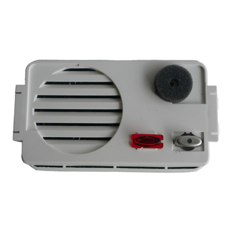
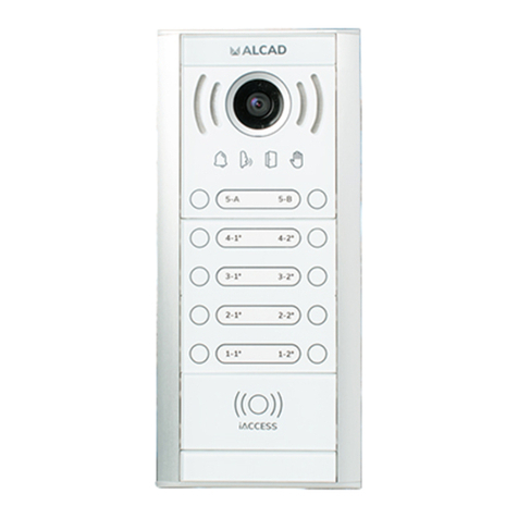
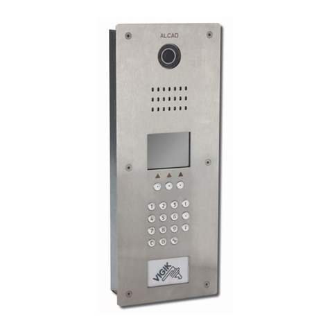
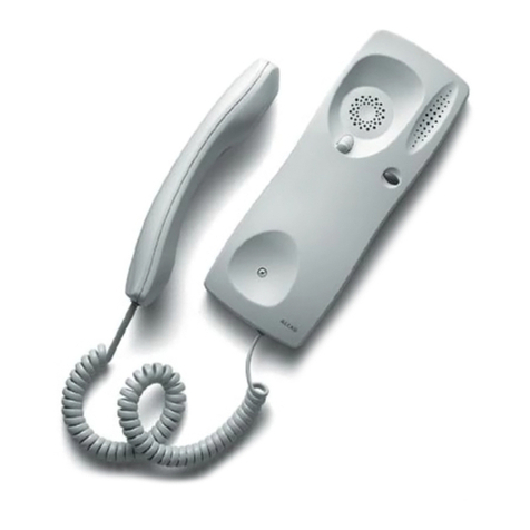
Alcad KVS-31121 User manual

KITS
MANUAL DE INSTALACIÓN
KVS-31121
INSTALLATION DATA SHEET
FEUILLE D’INSTALLATION
...................2
...................9
..................16
MVC-132
1 2 3 4
+–5 6
MVC-132
1 2 3 4
+–5 6 V+ V+
100V
240V
~
ALC-260~
V- V-V+ V+
100V
240V
~
ALC-260~
V- V-
+–
15 Vdc
500mA
+–
15 Vdc
500mA
1 2
PDP-01011
5 61 2
PDP-01011
5 6
**
* No incluido en el Kit - Not included in the kit - Non Inclus dans le kit
A
B
Tabla de secciones
Section table
Tableau de sections
A: 50m
B: 20m
CAB-007
1mm2
AWG: 18
A: 100m
B: 30m
1.3 mm2
AWG: 16
Tabla de secciones
Section table
Tableau de sections
A: 50m
B: 20m
CAB-007
1mm2
AWG: 18
A: 100m
B: 30m
1.3 mm2
AWG: 16
VIDEO PORTERO 2 HILOS KIT - 2-WIRE KIT VIDEO DOOR ENTRY SYSTEMS - VIDEO PORTIER 2 FILS KIT

VIDEO PORTERO 2 HILOS KIT
ESP-2
ÍNDICE
ELEMENTOS Y DIMENSIONES ..................................................................................................................................................... 2
INSTALACIÓN DE ELEMENTOS ADICIONALES.................................................................................................................... 3
CONEXIÓN ABREPUERTAS AC .................................................................................................................................... 3
CONEXIÓN ABREPUERTAS INVERSO ....................................................................................................................... 3
PULSADOR AUXILIAR DEL MONITOR (CONEXIÓN DESDE EL MONITOR).................................................. 4
DOBLE PUERTA PEATONAL .......................................................................................................................................... 4
INSTRUCCIONES DE INSTALACIÓN ......................................................................................................................................... 5
ALIMENTADOR.................................................................................................................................................................... 5
SOPORTE DE MONITOR .................................................................................................................................................. 5
MONITOR............................................................................................................................................................................... 6
PLACA DE CALLE............................................................................................................................................................... 6
AJUSTE DEL VOLUMEN DE AUDIO.............................................................................................................. 6
AJUSTE DEL TIEMPO DE APERTURA DE PUERTA ................................................................................ 6
TARJETERO DEL PULSADOR......................................................................................................................... 7
CARACTERÍSTICAS TÉCNICAS................................................................................................................................................... 7
SOLUCIÓN DE PROBLEMAS ........................................................................................................................................................ 8
ELEMENTOS Y DIMENSIONES
Placa de calle Soporte para
placa de calle
Monitor
210 mm 25 mm
138 mm
90 mm
130 mm
Soporte de monitor
7”
107 mm 35 mm
157 mm
186 mm
108 mm
113 mm
86 mm
Alimentador
78 mm
97 mm
56 mm

VIDEO PORTERO 2 HILOS KIT
ESP-3
INSTALACIÓN DE ELEMENTOS ADICIONALES
CONEXIÓN ABREPUERTAS AC
CONEXIÓN ABREPUERTAS INVERSO
12 V~
1,5A
1 2
PDP-01011
5 6
*
* No incluido en el Kit
ASC-050
Ctrl1
Ctrl2
230V
~
ALA-040~
*
*
+–
Máx. 15V, 1,5A
230V
~
ALM-040 ~
+
–
1 2
PDP-01011
5 6
*
* No incluido en el Kit
ASC-050
Ctrl1
Ctrl2
*
*

VIDEO PORTERO 2 HILOS KIT
ESP-4
PULSADOR AUXILIAR DEL MONITOR (CONEXIÓN DESDE EL MONITOR)
DOBLE PUERTA PEATONAL
MVC-132
1 2 3 4
+–5 6
CONTACTO SECO
MVC-132
1 2 3 4
+–5 6 V+ V+
100V
240V
~
ALC-260 ~
V- V-
+–
15 Vdc
500mA
1 2
PDP-01011
5 6
*
* No incluido en el Kit
ASC-051
Ctrl1
Ctrl2
+–
15V
+–
–
OFF
230V
~
ALM-040 ~
+
–
+–
15 Vdc
1,5A
*
**

VIDEO PORTERO 2 HILOS KIT
ESP-5
SOPORTE DE MONITOR
Elija una zona de pared plana, uniforme y dura. Tenga en cuenta las dimensiones del monitor que
posteriormente conectará al soporte de conexiones. Colóquelo alejado de fuentes de luz directa, evitando
así efectos no deseados en la visualización de la imagen (reejos,...). Evite también fuentes intensas de calor,
humedad, vapor, que podrían limitar la vida útil del equipo.
Dimensiones del monitor y del
soporte de monitor
60 mm
138 mm
130 mm
90 mm
210 mm
4 mm
INSTRUCCIONES DE INSTALACIÓN
ALIMENTADOR
1 Montaje en carril DIN 2
Consulte las instrucciones de seguridad al nal del presente documento. Proteja el alimentador, cumpliendo
con la normativa vigente en materia de instalaciones eléctricas (magneto térmicos, diferenciales...).

VIDEO PORTERO 2 HILOS KIT
ESP-6
MONITOR
PLACA DE CALLE
1 2
Tiempo de apertura
de puerta
Volumen en
placa
0,3 Seg 3 Seg 6 Seg
3
No olvide ajustar el volumen de
audio y el tiempo de activación
del abre puertas antes de jar
la placa de calle a la pared.
AJUSTES DE LA PLACA DE CALLE:

VIDEO PORTERO 2 HILOS KIT
ESP-7
45 mm
11 mm
4
6 Tarjetero del pulsador
5
CARACTERÍSTICAS TÉCNICAS
MONITOR
ALIMENTADOR
REFERENCIA: 9620022 ALC-260
ALIMENTACIÓN DE RED: Tensión: 100-240 V~50/60Hz
Corriente: 0.88 A (máx.)
SALIDAS: Tensión: 18 V
Corriente: 2 A (máx.)
TEMPERATURA DE FUNCIONAMIENTO:
0.. +45 OC
REFERENCIA: 9630069 MVC-132
PANTALLA: 7” COLOR TFT LCD
ALIMENTACIÓN: DC18V/1.5A
CONSUMO: ≤3W (Reposo); ≤10W (Trabajo)
TONOS DE LLAMADA: 9 Tonos
INSTALACIÓN: De supercie
TEMPERATURA DE FUNCIONAMIENTO:
5.. +55 OC

VIDEO PORTERO 2 HILOS KIT
ESP-8
SOLUCIÓN DE PROBLEMAS
No funciona nada
Compruebe si el led del alimentador está
apagado.
a) Verique la tensión de red b) Desconecte las
bornas +, - del alimentador y verique que la
tensión en bornas sea de 18Vdc. Si no detecta
tensión en dichas bornas el alimentador podría
estar averiado. En caso contrario, compruebe si
existe algún cortocircuito en las conexiones +,-
entre los equipos de la instalación.
No es posible realizar llamada desde la pla-
ca de calle. No llega tensión a la placa de
calle
(Si existe tensión en las bornas 1,2 de la placa
de calle (15-18Vdc) vaya al punto siguiente. )
Desconecte los cables 1 y 2 del monitor y
verique la tensión en bornas. Si dicha tensión
es correcta verique el cable entre el monitor y
la placa de calle. Por el contrario, si la tensión
no es correcta, el monitor podría estar averiado.
No es posible realizar llamada desde la pla-
ca de calle
Verique que se encuentra dentro de los
límites del equipo. Para ello compruebe que
las distancias se ajustan a las que se indican
en la primera página de este manual, teniendo
en cuenta el tipo de cable empleado. Si no
encuentra el fallo, la placa de calle podría estar
averiada.
No se oye la placa de calle desde el monitor
Ajuste el volumen mediante el regulador de
volumen del monitor. Si no detecta el fallo,
el monitor o la placa de calle podrían estar
averiados.
No se oye el monitor desde la placa de calle
Ajuste el volumen mediante el regulador de
volumen de la placa de calle. Si no detecta el
fallo, el monitor o la placa de calle podrían estar
averiados.
La tensión suministrada al abrepuertas es
muy baja
La placa de calle está diseñada para enviar una
señal al abrepuertas de tipo impulso seguido
de una tensión de mantenimiento. No es
posible medir dicho impulso con un polímetro,
por lo que la medida registrada corresponde a
la tensión de mantenimiento, que podría estar
comprendida entre 3V y 14V. Esto permite la
activación de abrepuertas con bobinas de 10 a
50 ohmios, que se corresponde con la mayoría
de los abrepuertas existentes en el mercado,
por lo que no se trata de ninguna anomalía.
Si el abrepuertas no funciona vaya al punto
siguiente.
No funciona el abrepuertas
Si el abrepuertas tiene polaridad, asegúrese
que conecta el terminal positivo a la borna 5
y el terminal negativo a la borna 6 de la placa
de calle.
Verique que la resistencia en bornas del
abrepuertas se encuentre entre 10 y 50
ohmios, abrepuertas fuera de este rango son
incompatibles con el sistema.
Verique que le llega tensión al abrepuertas,
de no ser así, desconecte los cables 5 y 6 de la
palca de calle y verique la tensión en bornas,
si no hay tensión la placa de calle podría estar
averiada. De no ser así verique el cable entre
la placa de calle y el abrepuertas.
PLACA DE CALLE
REFERENCIA: 9800152 PDP-01011
CÁMARA: 1/3” Color CCD;1.5lux
CONEXIÓN: 2 Hilos no polarizados
CONSUMO: ≤0,7W (Reposo); ≤6W (Trabajo)
TIEMPO PARA CONTESTAR: 90 Seg
TIEMPO DE CONVERSACIÓN: 60 Seg
ABREPUERTAS: 10 Ω ~ 50 Ω. Corriente de
mantenimiento: ≤150mA
INSTALACIÓN: De supercie
TEMPERATURA DE
FUNCIONAMIENTO: -30.. +70 OC
ENG-9
2-WIRE KIT VIDEO DOOR ENTRY SYSTEMS
Entrance panel
Monitor Monitor bracket
Support for
entrance panel Power supply unit
210 mm 25 mm
138 mm
90 mm
130 mm
7”
107 mm 35 mm
157 mm
186 mm
108 mm
113 mm
86 mm
78 mm
97 mm
56 mm
INDEX
ELEMENTS AND DIMENSIONS.................................................................................................................................................... 9
INSTALLATION OF ADDITIONAL ELEMENTS......................................................................................................................10
HOW TO CONNECT AC ELECTRIC LOCK ...............................................................................................................10
HOW TO CONNECT INVERSE ELECTRIC LOCK ...................................................................................................10
MONITOR AUXILIARY PUSH-BUTTON (CONNECTION FROM THE MONITOR).......................................11
DOUBLE PEDESTRIAN DOOR.....................................................................................................................................11
INSTALLING INSTRUCTIONS .....................................................................................................................................................12
POWER SUPPLY UNIT....................................................................................................................................................12
MONITOR BRACKET........................................................................................................................................................12
MONITOR.............................................................................................................................................................................13
ENTRANCE PANEL ..........................................................................................................................................................13
ADJUSTING THE VOLUME.............................................................................................................................13
ADJUSTING UNLOCK TIME ..........................................................................................................................13
PUSHBUTTON CARDHOLDER....................................................................................................................14
TECHNICAL CHARACTERISTICS..............................................................................................................................................14
TROUBLE SHOOTING....................................................................................................................................................................15
ELEMENTS AND DIMENSIONS

ENG-10
2-WIRE KIT VIDEO DOOR ENTRY SYSTEMS
INSTALLATION OF ADDITIONAL ELEMENTS
HOW TO CONNECT AC ELECTRIC LOCK
HOW TO CONNECT INVERSE ELECTRIC LOCK
12 V~
1.5A
1 2
PDP-01011
5 6
*
* Not included in the kit
ASC-050
Ctrl1
Ctrl2
230V
~
ALA-040~
*
*
* Not included in the kit
+–
Max. 15V, 1.5A
230V
~
ALM-040 ~
+
–
1 2
PDP-01011
5 6
*
ASC-050
Ctrl1
Ctrl2
*
*

ENG-11
2-WIRE KIT VIDEO DOOR ENTRY SYSTEMS
MVC-132
1 2 3 4
+–5 6
DRY CONTACT
MVC-132
1 2 3 4
+–5 6 V+ V+
100V
240V
~
ALC-260 ~
V- V-
+–
15 Vdc
500mA
1 2
PDP-01011
5 6
*
* Not included in the kit
ASC-051
Ctrl1
Ctrl2
+–
15V
+–
–
OFF
230V
~
ALM-040 ~
+
–
+–
15 Vdc
1.5A
*
**
MONITOR AUXILIARY PUSH-BUTTON (CONNECTION FROM THE MONITOR)
DOUBLE PEDESTRIAN DOOR

ENG-12
2-WIRE KIT VIDEO DOOR ENTRY SYSTEMS
MONITOR BRACKET
Choose an area of wall which is smooth, even and hard. Bear in mind the dimensions of the monitor which
will later be connected to the connection bracket. Avoid places where there are sources of direct light, thereby
preventing undesired reections on the screen of the monitor. Similarly, avoid sources of strong heat, damp
or steam, which could reduce the operational life of the equipment.
INSTALLING INSTRUCTIONS
POWER SUPPLY UNIT
See the safety instructions at the end of this booklet. Protect the power supply unit by complying with existing
regulations governing electrical installations (avoid high-temperature locations and strong magnetic elds,
ensure correct fusing, etc.).
Monitor and bracket size
60 mm
138 mm
130 mm
90 mm
210 mm
4 mm
1 Mounting on a DIN rail 2

ENG-13
2-WIRE KIT VIDEO DOOR ENTRY SYSTEMS
1 2
Unlock time setting
for electrc lock
Volume of the
panel
0,3 Sec 3 Sec 6 Sec
3
Do not forget to adjust
the audio volume and the
activation time of the electric
lock before attaching the
entrance panel to the wall.
ENTRANCE PANEL SETTINGS
MONITOR
ENTRANCE PANEL

ENG-14
2-WIRE KIT VIDEO DOOR ENTRY SYSTEMS
TECHNICAL CHARACTERISTICS
45 mm
11 mm
4
6 Pushbutton cardholder
5
MONITOR
REFERENCE: 9620022 ALC-260
MAINS SUPPLY:
Voltage: 100-240 V~50/60Hz
Current: 0.88 A (max.)
OUTPUTS:
Voltage: 18 V
Current: 2 A (max.)
OPERATING TEMPERATURE: 0.. +45 OC
REFERENCE: 9630069 MVC-132
SCREEN: 7” COLOR TFT LCD
IMPUT POWER: DC18V/1.5A
CONSUMPTION: ≤3W (Standby); ≤10W (Working)
RINGTONE: 9 Ringtones
INSTALLATION: Surface mount
OPERATING TEMPERATURE: 5.. +55 OC
POWER SUPPLY UNIT

ENG-15
2-WIRE KIT VIDEO DOOR ENTRY SYSTEMS
TROUBLE SHOOTING
Nothing works
Check whether the power supply led is unlit.
a) Check the mains voltage b) Disconnect the
+, - terminals of the power supply and verify
that the voltage at the terminals is 18Vdc. If
there is no voltage detected at these terminals,
the power supply unit may be defective.
Otherwise, check if there is a short circuit in
the +, - connections between the devices of the
installation.
It is not possible to make a call from the en-
trance panel. There is no voltage in the en-
trance panel
(If there is voltage in terminals 1,2 of the
entrance panel (15-18Vdc) see the next point.)
Disconnect cables 1 and 2 of the monitor
and check the voltage in the terminals. If this
voltage is correct, check the cable between the
monitor and the entrance panel. Otherwise, if
the voltage is not correct, the monitor may be
defective.
It is not possible to make a call from the en-
trance panel
Check the specications about distances and
cross section cables shown in the rst page of
this manual. If no fault is detected, the entrance
panel may be defective.
You cannot hear the entrance panel in the
monitor
Adjust the volume using the monitor’s volume
control. If no fault is detected, the monitor or
entrance panel may be defective.
You cannot hear the monitor from the en-
trance panel
Adjust the volume using the volume control on
the entrance panel. If no fault is detected, the
monitor or entrance panel may be defective.
The voltage supplied to the door opener is
very low
The entrance panel is designed to send an
impulse signal to the electric lock followed by
a maintain current. It is not possible to measure
this pulse with a tester, so the measurement
corresponds to the maintain current, which
could be between 3V and 14V. This allows
the activation of electric locks with coils of 10
to 50 ohms, which corresponds with most of
the electric locks, so it is not anomaly. If the
electrick lock is not working see the next point.
The electric lock is not working
If the electrick lock has polarity, check that
the positive terminal is connected to terminal
5 and the negative terminal to terminal 6 of
the entrance panel. Verify that the terminal
resistance of the door opener is between 10
and 50 ohms.
Verify that the voltage is present in the electric
lock, if not, disconnect cables 5 and 6 from
the entrance panel and check the voltage in
terminals, if there is no voltage the entrance
panel may be defective. If not, check the cable
between the entrance panel and the electric
lock.
ENTRANCE PANEL
REFERENCE: 9800152 PDP-01011
VIDEO UNIT: 1/3” Color CCD;1.5lux
CONNECTION: 2 Hilos no polarizados
POWER CONSUMPTION: ≤0,7W (Standby); ≤6W
(Working)
TIME TO ANSWER: 90 Sec
TIME FOR CONVERSATION: 60 Sec
ELECTRIC LOCK: 10 Ω ~ 50 Ω. Lock maintain
current: ≤150mA
INSTALLATION: Surface mount
OPERATING TEMPERATURE: -30.. +70 OC

FRA-16
VIDEO PORTIER 2 FILS KIT
SOMMAIRE
ÉLÉMENTS ET MESURES .............................................................................................................................................................16
INSTALLATION D’ÉLÉMENTS ADDITIONNELS...................................................................................................................17
BRANCHEMENT GÂCHES AC .....................................................................................................................................17
BRANCHEMENT GÂCHE À RUPTURE .....................................................................................................................17
BOUTON AUXILIAIRE DU MONITOR (CONNEXION DEPUIS LE MONITEUR)............................................18
DOUBLE PORTE................................................................................................................................................................18
INSTRUCTIONS D’INSTALLATION...........................................................................................................................................19
ALIMENTATION .................................................................................................................................................................19
SUPPORT POUR MONITOR..........................................................................................................................................19
MONITEUR..........................................................................................................................................................................20
PLATINE DE RUE...............................................................................................................................................................20
AJUSTEMENT DU VOLUME...........................................................................................................................20
AJUSTEMENT DU TEMP D’ACTIVATION DE LA GÂCHE....................................................................20
ÉTIQUETTE DU BOUTON-POUSSOIR.......................................................................................................21
CARACTÉRISTIQUES TECHNIQUES .......................................................................................................................................21
PROBLÈMES DE FONCTIONNEMENT.....................................................................................................................................22
Platine de rue
Moniteur Support pour moniteur
Support pour
plaque d’entrée Alimentation
210 mm 25 mm
138 mm
90 mm
130 mm
7”
107 mm 35 mm
157 mm
186 mm
108 mm
113 mm
86 mm
78 mm
97 mm
56 mm
ÉLÉMENTS ET MESURES

FRA-17
VIDEO PORTIER 2 FILS KIT
INSTALLATION D’ÉLÉMENTS ADDITIONNELS
BRANCHEMENT GÂCHES AC
12 V~
1,5A
1 2
PDP-01011
5 6
*
* Non Inclus dans le kit
ASC-050
Ctrl1
Ctrl2
230V
~
ALA-040~
*
*
* Non Inclus dans le kit
+–
Max. 15V, 1,5A
230V
~
ALM-040 ~
+
–
1 2
PDP-01011
5 6
*
ASC-050
Ctrl1
Ctrl2
*
*
BRANCHEMENT GÂCHE À RUPTURE

FRA-18
VIDEO PORTIER 2 FILS KIT
BOUTON AUXILIAIRE DU MONITOR (CONNEXION DEPUIS LE MONITEUR)
MVC-132
1 2 3 4
+–5 6
CONTACT SEC
MVC-132
1 2 3 4
+–5 6 V+ V+
100V
240V
~
ALC-260 ~
V- V-
+–
15 Vdc
500mA
1 2
PDP-01011
5 6
*
* Non Inclus dans le kit
ASC-051
Ctrl1
Ctrl2
+–
15V
+–
–
OFF
230V
~
ALM-040 ~
+
–
+–
15 Vdc
1,5A
*
**
DOUBLE PORTE

FRA-19
VIDEO PORTIER 2 FILS KIT
Dimenssion du moniteur et du
support de moniteur
60 mm
138 mm
130 mm
90 mm
210 mm
4 mm
2
INSTRUCTIONS D’INSTALLATION
ALIMENTATION
Veuillez vous en référer aux instructions de sécurité à la n de ce document. Protéger l’alimentation, en
accord avec la norme en matière d’installation électrique (magnéto thermiques, différentiels...)
1 Montage sur rail DIN
SUPPORT POUR MONITEUR
Choisissez une surface de mur plane, uniforme et dure. Tenez compte des dimensions du moniteur qui sera
ensuite connecté au support de connexions. Choisissez un endroit éloigné des sources de lumière directe,
évitant ainsi des problèmes de réexion sur l’écran. De même, évitez les sources intensives de chaleur,
d’humidité et de vapeur, qui sont susceptibles de réduire la vie du matériel.

FRA-20
VIDEO PORTIER 2 FILS KIT
1 2
Temps d’activation
de la gâche
Volume de la
plaque
0,3 Sec 3 Sec 6 Sec
3
N’oubliez pas de régler le
volume audio et le temps
d’activation de la gâche avant
de xer la plaque de rue au
mur.
RÉGLAGES DE LA PLAQUE DE
RUE
PLATINE DE RUE
MONITEUR
Table of contents
Languages:
Other Alcad Intercom System manuals

Alcad
Alcad MVC-140 User manual

Alcad
Alcad 201 Series User manual

Alcad
Alcad TCB-130 User manual

Alcad
Alcad TED-001 User manual

Alcad
Alcad 9650006 KPD-002 User manual

Alcad
Alcad TCB-072 User manual

Alcad
Alcad 972 Series User manual

Alcad
Alcad GRF-001 User manual

Alcad
Alcad 201 Series User manual

Alcad
Alcad 960 Series User manual

Alcad
Alcad CIC-231 User manual

Alcad
Alcad GRF-411 User manual

Alcad
Alcad TED-002 User manual

Alcad
Alcad 960 Series User manual

Alcad
Alcad 963 Series User manual

Alcad
Alcad 980 Series User manual

Alcad
Alcad 960 Series User manual

Alcad
Alcad TET-002 User manual

Alcad
Alcad 980 Series User manual

Alcad
Alcad PDK-61211 User manual