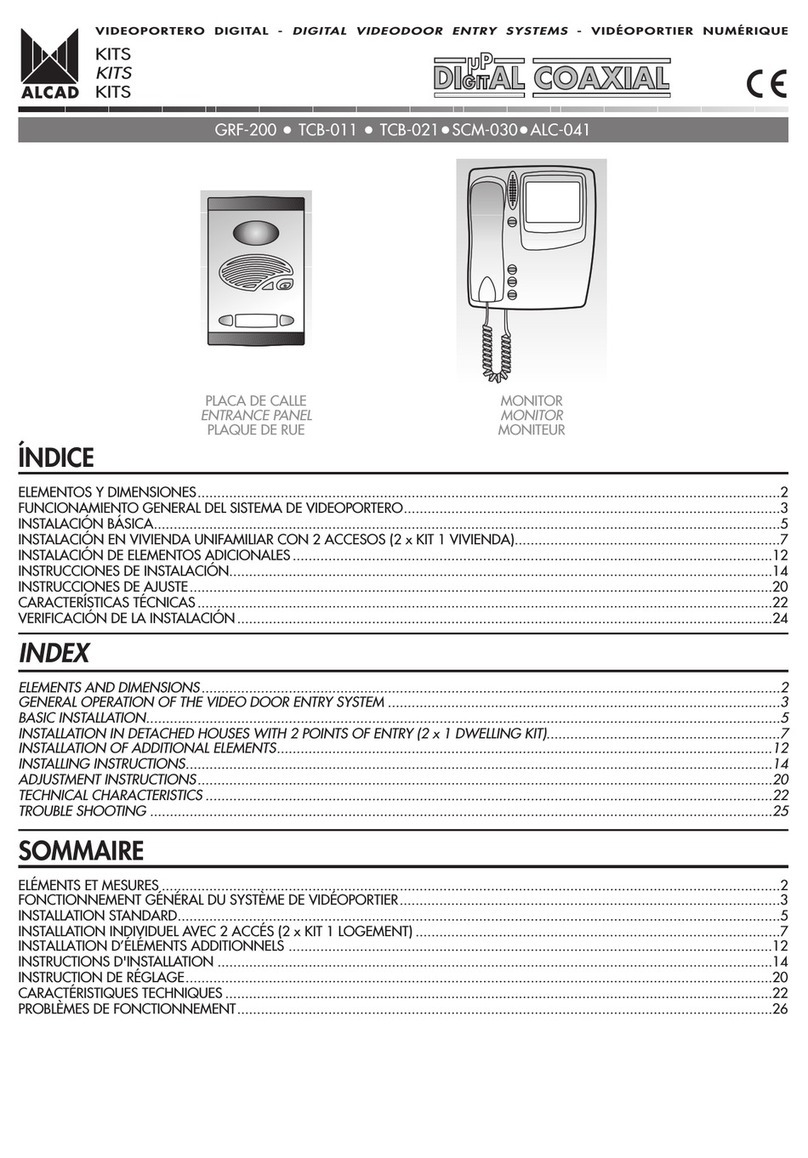
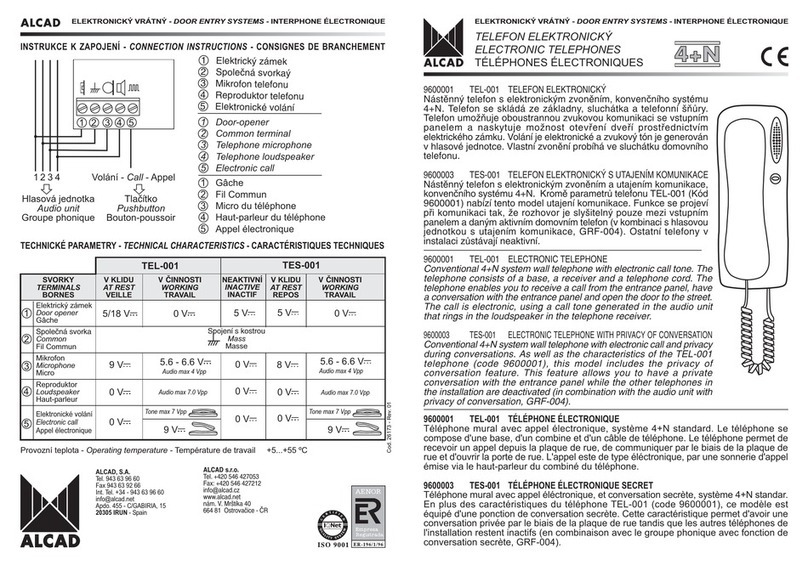
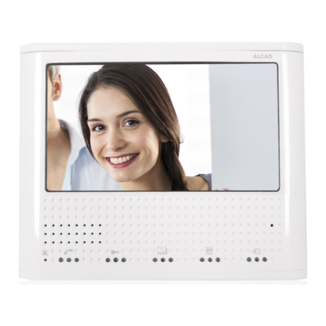
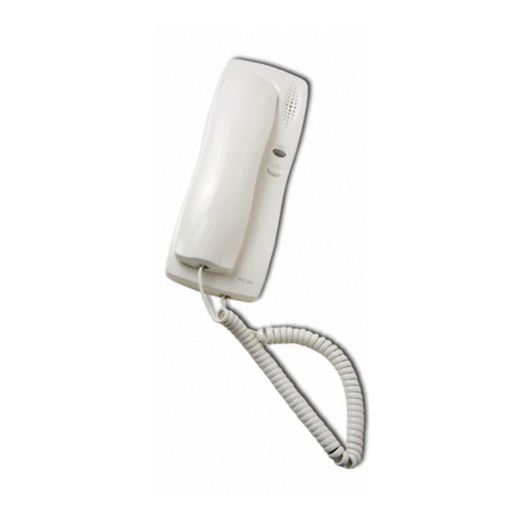
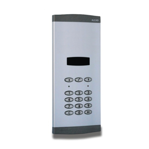
Alcad 967 Series User manual

ÍNDICE
DESCRIPCIÓN ..........................................................................................................................................................................2
ELEMENTOS Y DIMENSIONES ..................................................................................................................................................2
INSTALACIÓN BÁSICA .............................................................................................................................................................5
INSTALACIÓN CON VARIOS ACCESOS....................................................................................................................................7
INSTRUCCIONES DE CONEXIÓN............................................................................................................................................11
INSTRUCCIONES DE INSTALACIÓN Y AJUSTE.........................................................................................................................13
CARACTERÍSTICAS TÉCNICAS.................................................................................................................................................1
VERIFICACIÓN DE LA INSTALACIÓN.......................................................................................................................................18
INDEX
DESCRIPTION ...........................................................................................................................................................................2
ELEMENTS AND DIMENSIONS..................................................................................................................................................2
BASIC INSTALLATION ...............................................................................................................................................................5
INSTALLATION WITH SEVERAL POINTS OF ENTRY.....................................................................................................................7
CONNECTION INSTRUCTIONS...............................................................................................................................................11
INSTALLING AND ADJUSTMENT INSTRUCTIONS .....................................................................................................................13
TECHNICAL CHARACTERISTICS...............................................................................................................................................16
TROUBLE SHOOTING .............................................................................................................................................................2
SOMMAIRE
DESCRIPTION...........................................................................................................................................................................2
ELEMENTS ET MESURES............................................................................................................................................................2
INSTALLATION STANDARD .......................................................................................................................................................5
INSTALLATION AVEC PLUSIEURS ACCÉS....................................................................................................................................7
CONSIGNES DE BRANCHEMENT............................................................................................................................................11
IINSTRUCTIONS D'INSTALLATION ET DE RÉGLAGE ..................................................................................................................13
CARACTÉRISTIQUES TECHNIQUES..........................................................................................................................................1
PROBLÉMES DE FONCTIONNEMENT ......................................................................................................................................22
GRF-204 TCB-011 TCB-021
PLACA DE CALLE
ENTRANCE PANEL
PLAQUE DE RUE
SISTEMA DE VIDEOPORTERO CON PULSADORES
VIDEO DOOR ENTRY SYSTEMS WITH PUSH-BUTTONS
SISTÈMES DE VIDÉOPORTIER AVEC BOUTONS POUSOIRS
VIDEOPORTERO ELECTRÓNICO - VIDEODOOR ENTRY SYSTEMS - VIDÉOPORTIER ÉLECTRONIQUE

2
ELEMENTOS Y DIMENSIONES - ELEMENTS AND DIMENSIONS - ELEMENTS ET MESURES
PLACA DE CALLE - ENTRANCE PANEL - PLAQUE DE RUE
Módulos sim les - Simple modules - Modules sim les
MVN-301
MVN-302
Módulos dobles - Double modules - Modules doubles
MDN-441
MDN-442
9 70009 MVN-301
9 70045 MVN-302
128 mm 128 mm 12 mm
B
B: Ver hoja de normas del módulo de pulsadores.
B: See the push-button module datasheet.
B: Voir notice du module de boutons poussoirs.
9 70130 MDN-441
9 70151 MDN-442
12 mm
128 mm
B
B: Ver hoja de normas del módulo de pulsadores.
B: See the push-button module datasheet.
B: Voir notice du module de boutons poussoirs.
Sistema para instalaciones de edificios con uno o varios accesos (instalaciones de tamaño pequeño/medio).
Características:
Es posible instalar hasta 2 monitores y 2 teléfonos convencionales por vivienda con la misma llamada.
La placa de calle de un edificio se puede configurar como placa principal o secundaria, pudiendo conectar los monitores/teléfonos
a una u otra.
System for installations in buildings with one or several points of entry (small and médium-sized installations).
Cha acte istics
It is possible to install up to 2 monitors and 2 telephones per dwelling.
The entrance panel can be configured as main or secondary panel. The monitors/telephones can be connected to any of them.
Système pour installation dimmeubles avec un ou plusieurs accès (Installations de petites et moyennes tailles).
Caractéristiques:
Il est possible d'installer jusqu'à 2 moniteurs et 2 téléphones en parallèle per logement.
La plaque de rue peut se configurer comme plaque principale ou secondaire, ainsi les moniteurs/téléphones peuvent se connecter
aussi bien à lun comme à lautre.
MODELO
TYPE
RÉFERENCE
CÓDIGO
CODE
CODE
MODELO
TYPE
RÉFERENCE
CÓDIGO
CODE
CODE
9670009 MVN-301
Módulo de placa de calle con telecámara genérica B/N coaxial.
Entrance panel with generic B/W video unit coaxial.
Plaque d´entrée avec caméra générique N/B câble coaxial.
9670045 MVN-302
Módulo de placa de calle con telecámara genérica color coaxial.
Entrance panel with generic colour video unit coaxial.
Plaque d´entrée avec caméra générique couleur câble coaxial.
Nota: Para fijación a pared se precisa de caja de empotrar o caja de superficie. Consulte la hoja de normas correspondiente.
Note: For fixing to a wall, a flush-mounted or surface wall-mounted box is necessary. See the appropriate data sheet.
Note: Pour une fixation murale, il faudra un boîtier encastrtrable ou un boîter saillie. Voir notice correspondante.
DESCRIPCIÓN - DESCRIPTION - DESCRIPTION
VIDEOPORTERO ELECTRÓNICO - VIDEODOOR ENTRY SYSTEMS - VIDÉOPORTIER ÉLECTRONIQUE

3
MVN-903
MVN-905
Módulos tri les - T iple modules - Modules tri les
MDT-441
MDT-442
Placas com actas - Compact panels - Plaque com act
12 mm
128 mm
147 mm
9 7010 MVN-903
9 70107 MVN-905
B
9 70131 MDT-441
9 70152 MDT-442
12 mm
128 mm
B
B: Ver hoja de normas del módulo de pulsadores.
B: See the push-button module datasheet.
B: Voir notice du module de boutons poussoirs.
B: Ver hoja de normas del módulo de pulsadores.
B: See the push-button module datasheet.
B: Voir notice du module de boutons poussoirs.
MODELO
TYPE
RÉFERENCE
CÓDIGO
CODE
CODE
9670130 MDN-441
9670151 MDN-442
Módulo de placa de calle con MAN-441 y telecámara genérica color coaxial.
Entrance panel with MAN-441 and generic colour video unit coaxial.
Plaque d´entrée avec MAN-441 et caméra générique couleur câble coaxial.
Módulo de placa de calle con MAN-441 y telecámara genérica B/N coaxial.
Entrance panel with MAN-441 and generic B/W video unit coaxial.
Plaque d´entrée avec MAN-441 et caméra générique N/B câble coaxial.
MODELO
TYPE
RÉFERENCE
CÓDIGO
CODE
CODE
9670131 MDT-441
Módulo de placa de calle con MAN-441 y telecámara genérica B/N coaxial. Con tarjetero.
Entrance panel with MAN-441 and generic B/W video unit coaxial. With card holder.
Plaque d´entrée avec MAN-441 et caméra générique N/B câble coaxial. Avec porte étiquete.
9670152 MDT-442
Módulo de placa de calle con MAN-441 y telecámara genérica color coaxial. Con tarjetero.
Entrance panel with MAN-441 and generic colour video unit coaxial. With card holder.
Plaque d´entrée avec MAN-441 et caméra générique couleur câble coaxial. Avec porte étiquete.
VIDEOPORTERO ELECTRÓNICO - VIDEODOOR ENTRY SYSTEMS - VIDÉOPORTIER ÉLECTRONIQUE

4
MÓDULOS INTERIORES - INSIDE MODULES - MODULES INTERIEURS
9640002 TCB-011
Telecámara genérica B/N para cable coaxial.
Generic B/W video unit, coaxial.
Caméra générique N/B, coaxial.
9640009 TCB-021
Telecámara genérica color para cable coaxial.
Generic colour video unit, coaxial.
Caméra générique couleur, coaxial.
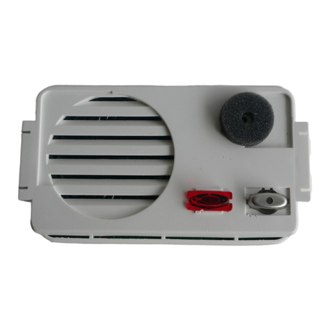
9610030 GRF-204
Grupo fónico 4+N microprocesado, con llamada electrónica, secreto y múltiples accesos. Nueva placa de calle.
4+N system audio unit, with electronic call, confidentiality feature and several points of entry. New entrance pannel.
Groupe phonique système 4+N, avec appel électronique, secret de communication et plusieurs accés. Nouvelle plaque de rue.
9670106 MVN-903
Placa compacta con telecámara genérica B/N coaxial.
Compact panel with generic B/W coaxial video unit.
Plaque compact avec caméra générique N/B câble coaxial.
9670107 MVN-905
Placa compacta con telecámara genérica color coaxial.
Compact panel with generic colour coaxial video unit.
Plaque compact avec caméra générique couleur câble coaxial.
9610030
GRF-204
MÓDULO
MODULE
MODULE
9640002
TCB-011
9640009
TCB-021
MDN-441
MDN-442
MVN-302
MVN-301
MVN-905
MVN-903
MDT-441
MDT-442
VIDEOPORTERO ELECTRÓNICO - VIDEODOOR ENTRY SYSTEMS - VIDÉOPORTIER ÉLECTRONIQUE

5
230 V V230 V V
Funcionamiento - Ope ation - Fonctionnement
MPD-004
MDN-441
MDN-442
ABR-001
(2)
COAX
DIV-024
SCM-010
MVB-001
MVC-001
ALM-040
(230 V )
ALA-040
(230 V )
(2) Máx. 12 Vac, 800 mA
(1) Utilice manguera independiente
Use separate cable hose.
Utiliser une gaine indépendante.
COAXIAL 75 W
TABLA DE SECCIONES
SECTION TABLE
TABLEAU DE SECTIONS
0,5 mm20,8 mm 20
0,75 mm21,0 mm 18
1 mm21,1 mm 17
2
3
4
0,25 mm20, mm 221
1,1 mm 17
0,8 mm 20
0,5 mm2
1 mm 2
Hasta 25 m - Up to 25 m - Jusqu'à 25 m
Hasta 100 m - Up to 1 m - Jusqu'à 100 m
AWG
(3)
1 mm 21,1 mm 17
COAX
COAX
COAX
ESQUEMA UNIFILAR - SINGLE-WIRED DIAGRAM - SCHÉMA À UN FIL
INSTALACIÓN BÁSICA - BASIC INSTALLATION - INSTALLATION STANDARD
(3) Sección en función del número de monitores/teléfonos en la vivienda.
Section according to the number of monitors/telephones in the dwelling.
Section en fonction du nombre de moniteurs/téléphones dans le logement.
VIDEOPORTERO ELECTRÓNICO - VIDEODOOR ENTRY SYSTEMS - VIDÉOPORTIER ÉLECTRONIQUE
4+N
2
2
5
5
2
2
2
(1)
Configure la placa de calle como placa principal (puente J1 colocado), vea paso de la página 14.
SISTEMA EN REPOSO
Los monitores/teléfonos están inactivos (funciones de comunicación y apertura de puerta inhabilitadas). Es posible activar el sistema
de autoencendido del monitor.
SISTEMA ACTIVO. RECEPCIÓN DE LLAMADA
Sólo los monitores/teléfonos asociados al pulsador recibirán la llamada. Confirmación de llamada en placa. Si el auricular del
monitor/teléfono está descolgado o no hay monitor/teléfono asociado a ese pulsador, la placa emitirá tonos intermitentes.
Tiempo para contestar: 30 segundos.
Tiempo de conversación máximo: 0 segundos. Prolongación tiempo de conversación: + 0 segundos.
Configure the panel as the main entrance panel (Leave J1 jumper in place), see step 6 on page 14.
SYSTEM ON STANDBY
The monitors/telephones are inactive (the functions of door opening and of communication with the entrance panel are disabled). It is
possible to activate the monitor's automatic switch-on system.
SYSTEM ACTIVATED. MAKING A CALL
Only the monitors/telephones associated to the push-button will receive the call. Confirmation of the call on the entrance panel. If the
handset of the monitor/telephone called is off the hook or there is no monitor/telephone associated with that push-button, intermittent
tones will be heard at the entrance panel.
Time setting to answer: 3 seconds.
Maximum time setting for conversation: 6 seconds. Extension of time for conversation: + 6 seconds.
Configurer la plaque de rue comme plaque principale (cavalier J1 installé), voir paragraphe page 14.
SYSTÈME EN VEILLE
Les moniteurs/téléphones sont inactifs (Les fonctions d'ouverture de porte et de communication avec la plque de rue sont inhibées). Il
est impossible activer les systèmes d'auto-allumage du moniteur.
SYSTÈME ACTIVÉ. RÉCEPTION D'APPELS
Seul le moniteur/téléphone associé á un bouton poussoir recevra l'appel. Confirmation de lappel en plaque. Si le moniteur/téléphone
est décroché ou il n'y a aucun moniteur/téléphone associé avec ce bouton poussoir, la plaque émettra des tonalités intermitentes.
Temps pour répondre : 30 secondes
Temps de conversation disponible: 0 secondes. Prolongation du temps de conversation: + 0 secondes.
Llamadas
Calls
Appels
230 V
V
~
230 V
V
~
GRF-204
Made in Spain
J1 J2
19
V1
V1
25
26
27
24
M
M
54321
M
M
M
(1)
V1
V1
25
26
27
24
M
M
54321
M
M
M
TCB-011
TCB-021
GRF-204
19 +_
SCM-010
DIV-024
Llamada
Call
Appel
ABR-001
INSTALACIÓN BÁSICA - BASIC INSTALLATION - INSTALLATION STANDARD
ALA-040
230 V
ALM-040
230 V
Llamada
Call
Appel
(1) Utilice manguera independiente.
Use separate cable hose.
Utiliser une gaine indépendante.
VIDEOPORTERO ELECTRÓNICO - VIDEODOOR ENTRY SYSTEMS - VIDÉOPORTIER ÉLECTRONIQUE
75 Ohm
J1
Blanco
White
Blanc
Rojo
Red
Rouge
V2 M MV2 V1 M MV4
75 Ohm
R1
BJ1
R1
BJ1
Placa de calle principal
Main entrance panel
Plaque de rue principale
9
V~
10 11 12 1 2 3 4 713 14 15 16 17 18

7
MDN-441
MDN-442
230 V V230 V V230 V V230 V V
MPD-004
DIV-024
SCM-010
MVB-001
MVC-001
MDN-441
MDN-442
MPD-004
ABR-001
(2)
COAX
ABR-001
(2)
ALA-040
(230 V )ALM-040
(230 V ) ALA-040
(230 V )
ALM-040
(230 V )
COAXIAL 75 W
TABLA DE SECCIONES
SECTION TABLE
TABLEAU DE SECTIONS
0,5 mm20,8 mm 20
0,75 mm21,0 mm 18
1 mm21,1 mm 17
2
3
4
0,25 mm20, mm 221
1,1 mm 17
0,8 mm 20
0,5 mm2
1 mm 2
Hasta 25 m - Up to 25 m - Jusqu'à 25 m
Hasta 100 m - Up to 1 m - Jusqu'à 100 m
AWG
(3)
1 mm 21,1 mm 17
COAX
COAX
COAX
COAX
ESQUEMA UNIFILAR - SINGLE-WIRED DIAGRAM - SCHÉMA À UN FIL
INSTALACIÓN CON VARIOS ACCESOS
INSTALLATION WITH SEVERAL POINTS OF ENTRY
INSTALLATION AVEC PLUSIEURS ACCÉS
INSTALACIÓN CON 2 ACCESOS - INSTALLATION WITH 2 ACCESS POINTS - INSTALLATION AVEC 2 ACCÈS
(2) Máx. 12 Vac, 800 mA
(1) Utilice manguera independiente
Use separate cable hose.
Utiliser une gaine indépendante.
(3) Sección en función del número de monitores/teléfonos en la vivienda.
Section according to the number of monitors/telephones in the dwelling.
Section en fonction du nombre de moniteurs/téléphones dans le logement.
VIDEOPORTERO ELECTRÓNICO - VIDEODOOR ENTRY SYSTEMS - VIDÉOPORTIER ÉLECTRONIQUE
2
5
5
2
2
2
4+N
+N
2
2
2
2
(1) (1)
2

Funcionamiento - Ope ation - Fonctionnement
Configure una de las placas como principal (deje el punte J1 colocado). Configure el resto de las placas como placas secundarias
(retire el puente J1), vea paso de la página 14.
SISTEMA EN REPOSO
Los monitores/teléfonos están inactivos (funciones de comunicación y apertura de puerta inhabilitadas). Es posible activar el sistema
de autoencendido del monitor.
SISTEMA ACTIVO. RECEPCIÓN DE LLAMADA
Sólo los monitores/teléfonos asociados al pulsador recibirán la llamada. Confirmación de llamada en placa. Si el auricular del
monitor/teléfono está descolgado o no hay monitor/teléfono asociado a ese pulsador, la placa emitirá tonos intermitentes.
Tiempo para contestar: 30 segundos.
Tiempo de conversación máximo: 0 segundos. Prolongación tiempo de conversación: + 0 segundos.
Durante dichos tiempos el resto de las placas quedan inhabilitadas. La luz roja de estas placas parpadeará.
Configure one of the entrance panels as the main panel (Leave J1 jumper in place). Configure the remaining panels as secondary
panels. (Remove the J1 jumper), see step 6 on page 14.
SYSTEM ON STANDBY
The monitors/telephones are inactive (the functions of door opening and of communication with the entrance panel are disabled). It is
possible to activate the monitor's automatic switch-on system.
SYSTEM ACTIVATED. MAKING A CALL
Only the monitor/telephone associated to the push-button will receive the call. Confirmation of the call on the entrance panel. If the
handset of the monitor/telephone called is off the hook or there is no monitor/telephone associated with that push-button, intermittent
tones will be heard at the entrance panel.
Time setting to answer: 3 seconds.
Maximum time setting for conversation: 6 seconds. Extension of time for conversation: + 6 seconds.
During both these periods of time the other entrance panels in the system will be disabled and the red led will blink.
Configurer une des plaques de rue comme principale (cavalier J1 installé). Configurer les autres plaques comme plaques secondaires
(enlever le cavalier J1), voir paragraphe page 14.
SYSTÈME EN VEILLE
Les moniteurs/téléphones sont inactifs (les fonctions d'ouverture de porte et de communication avec la plaque de rue sont inhibées). Il
est impossible activer les systèmes d'auto-allumage du moniteur.
Seul le moniteur/téléphone associé á un bouton poussoir recevra l'appel. Confirmation de lappel en plaque. Si le moniteur/téléphone
est décroché ou il n'y a aucun moniteur/téléphone associé avec ce bouton poussoir, la plaque émettra des tonalités intermitentes.
Temps pour répondre : 30 secondes
Temps de conversation disponible: 0 secondes. Prolongation du temps de conversation: + 0 secondes.

Pendant ce temps le reste des plaques resteront inhibées et la led rouge clignotera.
8
VIDEOPORTERO ELECTRÓNICO - VIDEODOOR ENTRY SYSTEMS - VIDÉOPORTIER ÉLECTRONIQUE

GRF-204
Made in Spain
J1 J2
19
V1
V1
25
26
27
24
M
M
54321
V1
V1
25
26
27
24
M
M
54321
M
M
M
M
M
M
(1)
V2 M MV2
TCB-011
TCB-021
GRF-204
19
ABR-001
Llamadas
Calls
Appels
9
SCM-010
DIV-024
+_
Llamada
Call
Appel
ALA-040
230 V
ALM-040
Llamada
Call
Appel
230 V
V
~
230 V
V
~
INSTALACIÓN CON 2 ACCESOS - INSTALLATION WITH 2 ACCESS POINTS - INSTALLATION AVEC 2 ACCÈS
230 V
(1) Utilice manguera independiente.
Use separate cable hose.
Utiliser une gaine indépendante.
VIDEOPORTERO ELECTRÓNICO - VIDEODOOR ENTRY SYSTEMS - VIDÉOPORTIER ÉLECTRONIQUE
75 Ohm
75 Ohm
V1 MMV4
R1
BJ1
R1
BJ1
J1
Placa de calle principal
Main entrance panel
Plaque de rue principale
9
V~
10 11 12 1 2 3 4 713 14 15 16 17 18
Rojo
Red
Rouge
Blanco
White
Blanc
19
+
19

+_
GRF-204
Made in Spain
J1 J2
19
(1)
V2 M MV2
TCB-011
TCB-021
GRF-204
19
ABR-001
ALA-040
230 V
ALM-040
10
230 V
V
~
230 V
V
~
(1) Utilice manguera independiente.
Use separate cable hose.
Utiliser une gaine indépendante.
Llamadas - Calls - Appels
230 V
VIDEOPORTERO ELECTRÓNICO - VIDEODOOR ENTRY SYSTEMS - VIDÉOPORTIER ÉLECTRONIQUE
J1
75 Ohm
V1 MMV4
9
V~
10 11 12 1 2 3 4 713 14 15 16 17 18
Rojo
Red
Rouge
Blanco
White
Blanc
19
+
19

V1 MV4
M
V2 MV2
M
19
V2 MV2
M
19
19
Alimentador
Power supply
Alimentation
Grupo fónico
Audio unit
Groupe phonique
+_
_
+
V2 MV2
M
19
19
Grupo fónico
Audio unit
Groupe phonique
+_
V1, M Señal de vídeo hacia monitores - Vídeo signal to the monitors - Signal vidéo aux moniteurs
V2, M Señal de vídeo múltiple acceso - Video signal installations with several points of entry
Signal vidéo installations avec plusieurs accés
+, Tensión de alimentación - Power supply voltage - Tension d'alimentation
19 Control telecámara - Video unit control - Control d'une caméra
INSTRUCCIONES DE CONEXIÓN - CONNECTION INSTRUCTIONS - CONSIGNES DE BRANCHEMENT
CONEXIÓN TCB-011, TCB-021 - HOW TO CONNECT TCB-011, TCB-021 - BRANCHEMENT TCB-011, TCB-021
V1, M
Para instalaciones de múltiple acceso, extraer la resistencia de las bornas (V2, M)
donde vaya a conectar el cable coaxial (pasos 1 y 2).
For installations with several points of entry, extract the resistence from the terminals
(V2, M) where the coaxial cable is to be connected (steps 1 and 2).
Pour des installations avec plusieurs accés, ôter la résistance des bornes (V2, M)
ou le câble coaxial va être connectée (point 1 et 2).
Telecámara
(Instalación múltiples accesos)
Video unit
(Installation with several points of entry)
Caméra
(Installation avec plusieurs accés)
+_
V2, M
Instalación básica
Basic installation
Installation standard
Instalación múltiple acceso
Installation with several points of entry
Installation avec plusieurs accés
BORNAS - TERMINALS - BORNES
11
Telecámara
(Instalación múltiples accesos)
Video unit
(Installation with several points of entry)
Caméra
(Installation avec plusieurs accés)
VIDEOPORTERO ELECTRÓNICO - VIDEODOOR ENTRY SYSTEMS - VIDÉOPORTIER ÉLECTRONIQUE
75 Ohm
V2, M
Conductor interno
Internal conductor
Conducteur interne
Malla
Mesh
Tresse
COAXIAL
Blanco
White
Blanc
Blanco
White
Blanc
Rojo
Red
Rouge
Negro
Black
Noir
Rojo
Red
Rouge
Negro
Black
Noir

GRF-204
J1 J2
19
ABR-001
V , Tensión de Alimentación - Power supply voltage - Tension d'alimentation
1, 2 Abrepuertas de los teléfonos - Telephone lock release - Gâche des téléphones
3, 2 Micrófono de los teléfonos - Telephone microphone - Micro des téléphones
4, 2 Altavoz de los teléfonos - Telephone loudspeaker - Haut-parleur des téléphones
7, 2 Común de pulsadores - Common push-button terminal - Fil commun des boutons-poussoirs
9, 10 Iluminación de placa - Panel lighting - Éclairage de plaque
11, 12 Abrepuertas - Electric lock - Gâche
17,18 Múltiple acceso - Multiple access - Accèss multiple
19 Alimentación (instalación básica) y control telecámara - Alimentation (Basic installation) and video unit control
- Alimentation (Installation standard) et control d'une caméra
J1 Selección placa principal - Main panel selection - Sélection plaque principale
J2 Ajuste de precisión de volumen de audio - Precision adjustment of sound level - Réglage de précision du volume audio
BORNAS - TERMINALS - BORNES
Común ulsadores
Common push-buttons
Commun des boutons- oussoirs
Alimentador
Power supply
Alimentation
Monitores/Teléfonos
Monitors/Telephones
Moniteurs/Téléphones
Grupo fónico
(Instalación múltiples
accesos)
Audio unit
(Installation with several
points of entry)
Groupe phonique
(Installation avec
plusieurs accés)
Telecámara
Video unit
Caméra
Selección placa principal
(Instalación múltiples accesos)
Main panel selection
(Installation with several points of entry)
Sélection plaque principale
(Installation avec plusieurs accèss
V~,
17,18
4,3,2,1
CONEXIÓN GRF-204 - HOW TO CONNECT GRF-204 - BRANCHEMENT GRF-204
Ajuste de precisión
de volumen de audio
Precision adjustment
of sound level
Réglage de précision
du volume audio
Abre uertas - Elect ic lock - Gâche
Activación
Activation
Activation
Conexión
Connection
Connexion
Lám aras laca de calle
Ent ance panel lamps
Am eules de la laque de rue
12
VIDEOPORTERO ELECTRÓNICO - VIDEODOOR ENTRY SYSTEMS - VIDÉOPORTIER ÉLECTRONIQUE

INSTRUCCIONES DE INSTALACIÓN Y AJUSTE
INSTALLING AND ADJUSTMENT INSTRUCTIONS
INSTRUCTIONS D'INSTALLATION ET DE RÉGLAGE
13
Si desea fijar la placa de calle en la pared, es
preciso tener previamente instalado un elemento
de fijación (caja de empotrar, caja de superficie,...).
Consulte la hoja de normas correspondiente.
If you wish to fix the entrance panel to a wall, it is
necessary to have previously installed a means of
attachment (i.e. a flush-mounted box or surface
wall-mounted box). See the appropriate data sheets.
Si vous désirez fixer la plaque de rue au mur, il est
nécessaire dinstaller un élément de fixation (boîtier
encastrable, boîte en saillie,). Voir notice
correspondante.
1Una vez colocada la caja de empotrar, retire el
refuerzo.
Once the flush-mounted box has been put in place,
remove the reinforcement.
Une fois inséré le boîtier encastrable, enlever le
renfort.
2
Extraiga los tapones y las bisagras de la caja de
empotrar. Extraiga las dos bisagras que requiera
según quiera abrir la placa hacia la derecha, la
izquierda o hacia abajo.
Remove the protecting plugs and the fixing pins
from the flush-mounted box. Choose the two fixing
pins you want to hinge the panel on to, so that it
opens either to the right or to the left or downwards.
Extraire les bouchons et les charnières du boîtier
encastrable. Extraire les deux charnières nécessaires
pour une ouverture de la plaque vers la droite ou
la gauche ou par le bas.
3Introduzca las anillas de la placa sobre las bisagras.
Introduzca completamente en sus ranuras las
bisagras no utilizadas.
Place the rings of the panel over the extracted fixing
pins. The unused pins should be placed in their
slots.
Introduisez les anneaux de la plaque sur les
charnières. Introduisez complètement dans les
rainures les charnières non utilisées.
4
VIDEOPORTERO ELECTRÓNICO - VIDEODOOR ENTRY SYSTEMS - VIDÉOPORTIER ÉLECTRONIQUE
Retirar en el momento de
instalar la placa de calle
Remove when installing the
entrance panel
Retirer lors de l'installation
de la plaque de rue

GRF-204
J1 J2
19
GRF-204
J1 J2
19
14
Realice las conexiones eléctricas. Vea esquemas e
"Instrucciones de conexión", página 11.
Make the electrical connections. See diagrams and
"Connection instructions", page 11.
Réalisez les connexions électriques. Voir schémas
et "Instructions de branchement", page 11.
5
Main entrance panel
Placa de calle principal
Plaque de rue principale
All other entrance panels
Resto de placas de calle
Les autres plaques de rue
Ajuste el volumen de audio de la placa de calle y
de los monitores/teléfonos (1). En caso de precisar
un ajuste con mayor precisión, retire el puente J2
y repita el ajuste (2).
7
Adjust the volume controls of the entrance panel
and of the monitors/telephones (1). If an adjustment
of greater precision is required, remove the J2
jumper and repeat the adjustment (2).
Régler le volume du son de la plaque de rue et
des moniteurs/ téléphones (1). Dans le cas dun
réglage plus précis, enlever le cavalier J2 et répéter
le réglage.
Ajuste el ángulo de la telecámara hasta conseguir
la orientación deseada.
8
Adjust the video unit's view angle until getting the
desired orientation.
Réglé langle de vision de la caméra jusquà en
obtenir lorientation voulue.
Una vez realizadas las conexiones, determine la
placa principal del sistema (placa sobre la que
actúa el sistema de autoencendido). En instalaciones
básicas, deje el puente J1 colocado. En instalaciones
de varios accesos, retire los puentes J1 del resto
de las placas
Once it has been connected up, establish which is
the main entrance panel in the system (panel on
which the monitor's auto switch-on function
actuates). In standard installations, leave the J1
jumper in place. In installation of several points of
access, remove the J1 jumpers from the rest of the
panels.
Une fois les branchements terminés, déterminez la
plaque de rue principale du système (plaque sur
laquelle agit le système d'autoallumage du
moniteur). Dans les installations de base, laissez
le cavalier J1 monté. Dans les installations à plusieurs
accès, enlevez les cavaliers J1 des autres plaques.
6
VIDEOPORTERO ELECTRÓNICO - VIDEODOOR ENTRY SYSTEMS - VIDÉOPORTIER ÉLECTRONIQUE
J1 J1
J2

15
Ajuste los embellecedores superior e inferior.
Adjust the upper and lower decorative fittings.
Ajustez les enjoliveurs supérieurs et inférieurs.
11
Separe los embellecedores superior e inferior,
aflojando los tornillos de sujeción.
Separate the upper and lower decorative fittings,
by loosening the clamping screws.
Séparez les enjoliveurs supérieur et inférieur, en
dévissant les vis de fixation.
910 Cierre la placa, presiónela contra la caja de
empotrar y fíjela a la misma mediante los tornillos
de sujeción.
Close the panel, press it against the flush-mounted
box and fix it to this using the clamping screws.
Enfoncez-la plaque contre le boîtier encastrable et
fixez-la à ce boîtier grâce aux vis de fixation.
VIDEOPORTERO ELECTRÓNICO - VIDEODOOR ENTRY SYSTEMS - VIDÉOPORTIER ÉLECTRONIQUE

1
TELECÁMARA TCB-011, TCB-021 - VIDEO UNIT TCB-011, TCB-021 - CAMÉRA TCB-011, TCB-021
(2) En urbanizaciones, cuando la telecámara de la placa de calle exterior está activada.
(2) In estates, when the external entrance panel video unit is activated.
(2) Dans des résidences, lorsque la télécaméra de la plaque de rue extérieure est activée.
(1) En varios accesos, cuando cualquier telecámara de una placa de calle está activada.
(1) In cases of multiple points of entry, when any entrance panel video unit is activated.
(1) Dans des accès multiple, lorsque nimporte quelle caméra dune plaque de rue est activée.
Temperatura de funcionamiento - Operating temperature - Température de travail -10 .. +55 ºC
(1)
1 Vpp ±0,1 (75 W)
(1)
1 Vpp ±0,1 (75 W)
1 Vpp ±0,1 (75 W)
1 Vpp ±0,1 (75 W)
INACTIVO
INACTIVE
INACTIF
TRABAJO
WORKING
TRAVAIL
BORNAS
TERMINALS
BORNES
V1, M
V2, M
0 Vpp
0 Vpp
CARACTERÍSTICAS TÉCNICAS - TECHNICAL CHARACTERISTICS - CARACTÉRISTIQUES TECHNIQUES
TENSIONES USUALES SEGÚN EL ESTADO DEL EQUIPO
NORMAL VOLTAGES DEPENDING ON THE STATE OF THE EQUIPMENT
TENSIONS USUELLES EN FONCTION DE LÉTAT DE LÉQUIPEMENT
Temperatura de funcionamiento - Operating temperature - Température de travail -10 .. +55 ºC
Nota: Valores de referencia suministrados para la comprobación del equipo. No utilizar las bornas del equipo para alimentar
dispositivos adicionales sin consulta previa al fabricante.
Note: Reference values are provided only to enable the checking of equipment and are reliable. Do not use the terminals of the equipment
to feed additional devices without first consulting the manufacturer.
Note: Valeurs de références fournies pour la vérification de l'équipement et exclusivement. N'utiliser pas les bornes de l'équipement
pour alimenter des dispositifs supplémentaires sans information préalable du fabricant.
VIDEOPORTERO ELECTRÓNICO - VIDEODOOR ENTRY SYSTEMS - VIDÉOPORTIER ÉLECTRONIQUE
SENSOR
SENSOR
CAPTEUR
ILUMINACIÓN
LIGHTING
ILLUMINATION
ALIMENTACIÓN
POWER SUPPLY
ALIMENTATION
TCB-011
Leds infrarrojos
Infrared leds
Leds infrarouges
CCD B/N 1/3
CCD B/W 1/3
CCD N&B 1/3
15
200
TCB-021
Leds blancos
White leds
Leds blanches
CCD Color 1/4
CCD Colour 1/4
CCD Couleur 1/4
225
V
mA
(max)
ORIENTACIÓN
ORIENTATION
ORIENTATION 10o

17
17, 18 8
± 10%
V0 V
11, 12
Audio max. 4 Vpp
Audio max. 7.0 Vpp
1, 2
3, 2
4, 2
7, 2
9, 10
8
± 10%
V
0 V
14.5
± 10%
V
5. - . V
BORNAS
TERMINALS
BORNES
INACTIVO
INACTIVE
INACTIF
TRABAJO
WORKING
TRAVAIL
,V
5
± 10%
V
12
± 10%
V
12
± 10%
V
REPOSO
AT REST
VEILLE
0 V
0 V
14.5
± 10%
V
Tone max. 10.5 Vpp
0 V
0 V 12
± 10%
V
GRUPO FÓNICO GRF-204 - AUDIO UNIT GRF-204 - GROUPE PHONIQUE GRF-204
MONITOR MVB-001, MVC-001 - MONITOR MVB-001, MVC-001 - MONITEUR MVB-001, MVC-001
MVB-001 MVC-001
PANTALLA
SCREEN
ÉCRAN
Temperatura de funcionamiento - Operating temperature - Température de travail +5 .. +55 ºC
Nota: Valores de referencia suministrados para la comprobación del equipo. No utilizar las bornas del equipo para alimentar
dispositivos adicionales sin consulta previa al fabricante.
Note: Reference values are provided only to enable the checking of equipment and are reliable. Do not use the terminals of the equipment
to feed additional devices without first consulting the manufacturer.
Note: Valeurs de références fournies pour la vérification de l'équipement et exclusivement. N'utiliser pas les bornes de l'équipement
pour alimenter des dispositifs supplémentaires sans information préalable du fabricant.
Temperatura de funcionamiento - Operating temperature - Température de travail -10 .. +55 ºC
VIDEOPORTERO ELECTRÓNICO - VIDEODOOR ENTRY SYSTEMS - VIDÉOPORTIER ÉLECTRONIQUE
CRT B/N plana de 4
4 CRT B/N flat
CRT B/N plat de 4
TFT color de 4
4 TFT colour
TFT couleur de 4

No funciona nada.
Verifique la tensión de red en los alimentadores. Verifique que la
tensión entre y V del alimentador sea 12 ± 10% Vac. Compruebe
si existe algún cortocircuito y soluciónelo. Desconecte el alimentador
de la red durante 1 minuto y vuelva a conectarlo. Si la avería
continúa, desconecte todas las bornas de , V del alimentador,
y verifique que la tensión entre y V sea 12 ± 10% Vac. Si no
es correcta, el alimentador puede estar averiado.
No se ilumina el iloto del ulsador de iluminación
Verifique que la tensión entre y V del grupo fónico sea 12 ±
10% Vac. Si la tensión es correcta, el grupo fónico puede estar
averiado.
No se iluminan los tarjeteros.
Verifique que la tensión entre 9 y 10 del grupo fónico, con el
pulsador de iluminación accionado, sea 12 ± 10% Vac. Compruebe
que la lámpara no esté fundida.
No suena la llamada en ningún monitor/teléfono.
Verifique que la tensión entre 7, 2 del grupo fónico, sin accionar
el pulsador, sea de 14,5 ± 10% Vdc. Revise la conexión entre 7
del grupo fónico y los pulsadores. Revise la conexión 2 del grupo
fónico hacia los monitores. Si no detecta el fallo, el grupo fónico
puede estar averiado.
No suena la llamada en un monitor.
Compruebe que el auricular está colgado. Compruebe la conexión
entre el soporte de conexiones y el monitor. Revise las conexiones
5, 2 del soporte de conexiones hacia el grupo fónico. Verifique
la conexión del pulsador en la placa de calle. Si no detecta el
fallo, el monitor o el pulsador de la placa pueden estar averiados.
No se oye la confirmación de llamada en la laca de calle.
Compruebe que se oyen los monitores en la placa de calle.
Compruebe que suena la llamada en los monitores. Si no detecta
el fallo, el grupo fónico puede estar averiado.
No se oye ningún monitor/teléfono desde la laca de calle.
Revise las conexiones 3, 2 del grupo fónico hacia todos los
monitores/teléfonos. Compruebe el regulador de volumen de la
placa. Si no detecta el fallo, el grupo fónico puede estar averiado.
No se oye un monitor/teléfono desde la laca de calle.
Revise las conexiones 3, 2 del soporte de conexiones/teléfono
hacia el grupo fónico. Si no detecta el fallo, el soporte de
conexiones/teléfono o el monitor puede estar averiado.
No se oye la laca de calle en ningún monitor/teléfono.
Revise las conexiones 4, 2 del grupo fónico hacia todos los
monitores. Compruebe el regulador de volumen de los
monitores/teléfonos en la placa de calle. Si no detecta el fallo,
el grupo fónico puede estar averiado.
No se oye la laca de calle en un monitor/teléfono.
Revise las conexiones 2 y 4 del soporte de conexiones/teléfono
hacia el grupo fónico. Si no detecta el fallo, el monitor puede
estar averiado.
El sonido se aco la.
Baje el volumen del sonido mediante los reguladores de volumen
del grupo fónico. Si el acoplo persiste, retire el puente J2 y repita
el ajuste (ver paso 7 de página 14).
No funciona el abre uertas.
Verifique que la tensión entre 1, 2 del grupo fónico, sin pulsar el
botón del abrepuertas, sea 5 ± 10% Vdc. Verifique que la tensión
entre 11, 12 del grupo fónico, pulsando el botón del abrepuertas,
sea 12 ± 10% Vac. En instalaciones de múltiple acceso, verifique
las conexiones 17, 18 entre las diferentes placas del sistema. Si
no detecta el fallo, la cerradura puede estar averiada.
En instalaciones de múlti le acceso, llamando en una de las
lacas de calle no se inhabilitan el resto de lacas del sistema.
Verifique las conexiones 17, 18 entre las diferentes placas del
sistema. Verifique que la tensión entre 17, 18 de todas las placas
es de 8 ± 10% Vdc, cuando se activa una de las placas. Si no
detecta el fallo, el grupo fónico puede estar averiado.
El sistema de video no funciona en ningún monitor:
autoencendido, encendido de antalla al recibir llamada,..
Verifique la tensión de red en el alimentador que alimenta a los
monitores. Si es el caso verifique la tensión de red en el alimentador
que alimenta a las telecámaras. Compruebe las conexiones +, -
de las telecámaras y verifique que la tensión sea 15 ± 10% Vdc.
Verifique que la tensión entre +, - en el alimentador sea 15 ± 10%
Vdc. Compruebe si existe algún cortocircuito y soluciónelo.
Desconecte el alimentador de la red durante 1 minuto y vuelva
a conectarlo. Si la anomalía persiste, desconecte todas las bornas
de +, - del alimentador, y verifique que la tensión entre +, - sea
15 ± 10% Vdc. Si no es correcta, el alimentador puede estar
averiado.
El sistema de video no funciona en un monitor: autoencendido,
encendido de antalla al recibir llamada,..
Compruebe que el interruptor del monitor para desactivar el video
está en la posición ON (a la izquierda). Compruebe que el led
rojo del monitor está encendido. Compruebe la conexión entre
el monitor y el soporte de conexiones. Verifique que la tensión
entre +, - del soporte de conexiones sea de 14 Vdc ± 15%. Si no
encuentra el fallo, el monitor puede estar averiado.
Problemas en la imagen en todos los monitores: imagen
distorsionada, doble imagen, érdida de sincronismo.
En caso de múltiple acceso, compruebe que tiene una única placa
definida como principal. Compruebe las conexiones +, - de las
telecámaras y verifique que la tensión sea 15 ± 10% Vdc.
Si la distribución se realiza a través de distribuidores, compruebe
que la tensión entre +, -de los distribuidores sea de 14 Vdc ±
15%. Verifique que la línea del cable coaxial está cargada con
75 ohmios: a) en caso de conectar derivadores en serie debe
retirar la resistencia de 75 ohmios de todos los derivadores
intermedios; b) en instalación de monitores en serie cortar las
resistencias de 75 ohmios de todos los soportes de conexiones
excepto del de final de línea; c)Verifique que las resistencias de
75 ohmios están conectadas en las bornas V2, M no utilizadas.
Verifique las conexiones de derivadores y distribuidores. Si no
detecta el fallo, la telecámara puede estar averiada.
Problemas en la imagen en un monitor: imagen distorsionada,
doble imagen, érdida de sincronismo.
Verifique que la línea del cable coaxial está cargada con 75
ohmios: en instalación con monitores en serie cortar las resistencias
de 75 ohmios de todos los soportes de conexiones excepto del
de final de línea. Si no detecta el fallo, el monitor puede estar
averiado.
El autoencendido no funciona en ningún monitor.
Verifique que ha definido una placa de calle como principal. Si
es el caso revise las conexiones 17, 18 de los equipos de la
instalación. Verifique que la tensión entre 1, 2 del grupo fónico
sin pulsar el botón de autoencendido sea 5 ± 10% Vdc. Si no
detecta el fallo, el grupo fónico puede estar averiado.
El autoencendido no funciona en un monitor.
Compruebe que al pulsar el botón de autoencendido, el led rojo
del monitor parpadea. Compruebe que el sistema no está ocupado.
Si no encuentra el fallo el soporte de conexiones o el monitor
pueden estar averiados.
Imagen en blanco en todos los monitores.
Compruebe la conexión entre la telecámara y el grupo fónico.
Verifique que el cable coaxial hacia monitores sale de las bornas
V1, M de la telecámara. Si es el caso, revise las conexiones V2,
M de las telecámaras de la instalación. Si la distribución se realiza
a través de distribuidor, compruebe que la tensión entre +, - del
distribuidor sea de 14 Vdc ± 15%. Verifique las conexiones del
cable coaxial de la telecámara hacia monitores. Si no detecta el
fallo, el grupo fónico, la telecámara o el distribuidor pueden estar
averiados.
Imagen en blanco en todos los monitores de una vivienda.
Verifique la posición del puente J1 de configuración de los soportes
de conexiones. Revise las conexiones del cable coaxial desde los
soportes de conexiones hacia la telecámara. Si la distribución en
la vivienda se realiza a través de distribuidor, compruebe que la
tensión entre +, - del distribuidor sea de 14 Vdc ± 15%. Si no
encuentra el fallo, el derivador de esa planta o el distribuidor de
la vivienda pueden estar averiados.
VERIFICACIÓN DE LA INSTALACIÓN
18
VIDEOPORTERO ELECTRÓNICO - VIDEODOOR ENTRY SYSTEMS - VIDÉOPORTIER ÉLECTRONIQUE

19
Imagen en blanco en uno de los monitores de una vivienda.
Revise la conexión entre el soporte de conexiones y el monitor.
Revise las conexiones del coaxial en el soporte de conexiones del
monitor. Si la distribución en la vivienda se realiza a través de
distribuidor, verifique la posición del puente J1 de configuración
del soporte de conexiones. Revise las conexiones del cable coaxial
desde el soporte de conexiones hacia la telecámara. Si no encuentra
el fallo, el soporte de conexiones, el monitor, o el distribuidor de
la vivienda pueden estar averiados.
VIDEOPORTERO ELECTRÓNICO - VIDEODOOR ENTRY SYSTEMS - VIDÉOPORTIER ÉLECTRONIQUE

20
Nothing wo ks.
Check the mains voltage in the power supply unit that feeds the
audio unit. Check that the voltage between y V of the power
supply is 12 ±1 % Vac. Check for the existence of a short circuit
and rectify this. Disconnect the power supply for 1 minute and
then reconnect it. If ithe breakdown continues, disconnect all the
power supply and V terminals, and check that the voltage
between and V is 12 ±1 %Vac. If you cannot find the fault,
there may be something wrong with the power supply.
The lighting push-button pilot does not light up.
Check that the voltage between and V in the audio unit is 12
± 1 % Vac. If the voltage is correct, there may be something
wrong with the audio unit.
The ca d holde s do not light up.
Check that the voltage between 9 and 1 in the audio unit, with
the lighting push-button activated, is 12 ±1 % Vac. Check whether
the lamp is burnt out.
The call tone doesnt ing on any monito /telephone.
Check that the voltage between 7, 2 in the audio unit, without
pressing the push-button, is 14.5 ± 1 % Vdc. Check the connection
between 7 in the audio unit and the push-buttons. Check connection
2 from the audio unit to the monitors. If you cannot find the fault,
there may be something wrong with the audio unit.
The call tone doesnt ing in a monito .
Check that the handset is not off the hook. Check the connection
between the connection bracket and the monitor. Check connections
5, 2 from the conection bracket to the entrance panel. Check the
push-button connection on the audio unit. If you cannot find the
fault, there may be something wrong with monitor or the panel
push-button.
You cannot hea the call confi mation on the ent ance panel.
Check that you can hear the monitors on the entrance panel.
Check that the call tone rings on the monitors/telephones. If you
cannot find the fault, there may be something wrong with the
audio unit.
No monito /telephone can be hea d f om the ent ance panel.
Check connections 3, 2 from the audio unit to all the
monitors/telephones. Check the volume control on the panel. If
you cannot find the fault, there may be something wrong with the
audio unit.
One monito /telephone cannot be hea d f om the ent ance
panel.
Check connections 3, 2 from the connection bracket/telephone
to the audio unit. If you cannot find the fault, there may be
something wrong with the connection bracket/telephone or the
monitor.
You cannot hea an ent ance panel on any monito /telephone.
Check connections 4, 2 from the audio unit to all the
monitors/telephones. Check the volume control on the monitors
(on the panel). If you cannot find the fault, there may be something
wrong with the audio unit.
You cannot hea the ent ance panel on a monito /telephone.
Check connections 2 and 4 from the connection
bracket/telephone to the audio unit. If you cannot find the
fault, there may be something wrong with the monitor.
The sound p oduces feedback.
Lower the sound level using the volume control on the audio unit.
If the feedback persists, remove the J2 jumper and repeat the
adjustment (see step 7 on page 14).
The elect ic lock doesnt wo k.
Check that the voltage between 1, 2 in the audio unit, without
pressing the lock release button, is 5 ± 1 % Vdc. Check that the
voltage between 11, 12 in the audio unit, when you press the lock
release button, is 12 ± 1 % Vac. In multiple access installations,
make certain that connectors 17, 18 on the panels are connected
up. If you cannot find the fault, the lock may be broken.
In multiple access installation, when you call one of the panels
the est of the panels in the system a e not disabled.
Make certain that connectors 17, 18 on the panels are connected
up. Check that the voltage between 17, 18 in each one of the
audio unit is 8 ±1 % Vdc when you press the push-button on one
of the panels. If you cannot find the fault, there may be something
wrong with the audio units.
The video system does not wo k in any monito : auto switch-
on, sc een doesn´t come on when eceiving a call,..
Check the mains voltage in the power supply unit that feeds the
monitors. Check that the voltage of the power supply between -
and + is 15 ± 1 % Vdc. Check the +, - conexion between the
power supply and the audio unit. Check if there's a short circuit
and rectify it. Disconnect the power supplies supply for 1 minute
and reconnect it. If the breakdown continues, disconnect all the
- and + terminals from the power supply unit and check that
voltage between - and + is 15 ± 1 % Vdc. If it's not correct, there
may be something wrong with the power supply.
Video system does not wo k in one monito : auto switch-on,
sc een doesn´t come on when eceiving a call,..
Check that the ON/OFF switch for the video is in ON position
(on the left). Check that the red led of the monitor is on. Check the
connection between the connection bracket and the monitor. Check
that the voltage between - and + of the connection bracket is 14
± 15% Vdc. If failure cannot be found, there may be something
wrong with the monitor.
Poo image quality on all the monito s: disto ted pictu e, ghost
images, loss of synch onisation.
In multiple access installation, check that you have only one
entrance panel defined as the main one. If splitters have been
used in the distribution, check that the voltage between - and +
of the splitters is 14 ± 15% Vdc. Check that coaxial cable line has
a 75 Ohm load: a) if tap-offs have been connected in series the
75 Ohm resistance must be removed from all the intermediate
tap-offs; b) with monitors in series cut the 75 Ohm resistances on
all the connection brackets, but from the one at the end of the line;
c) Check coaxial connection in splitters and tap-offs. If you cannot
find the fault, there may be something wrong with the video unit.
Check that resistences of 75 ohms are connected in the unused
terminals V2, M. If you cannot find the fault, there may be something
wrong with the video unit.
Poo image quality on one monito : disto ted pictu e, ghost
images, loss of synch onisation.
Check that coaxial cable line is charged with 75 Ohm: iwith
monitors in series cut the 75 Ohm resistances on all the connection
brackets, but from the one at the end of the line. If you cannot
find the fault there may be something wrong with the monitor.
Auto switch-on does not wo k on any monito .
In multiple access installations, check that one entrance panel has
been defined as the main one and check connections 17, 18
between different entrance panels. Check that the voltage between
1, 2 of the audio unit, without pushing the auto switch-on button
is 5 ± 1 % Vdc. If you cannot find the fault there may be something
wrong with the audio unit.
Auto switch-on does not wo k on one monito .
Check that pushing the auto switch-on button the red led flash.
Check that the system is not engaged. If you cannot find the fault,
there may be something wrong with the connection bracket or the
monitor.
Blank sc een on all the monito s.
Check the connection between the video and the audio units.
Check that the coaxial cable to the monitors is connected to the
V1 and M terminals of the video unit. If this is the case, check
connections V2, M and V4, M of the video units of the installation.
If splitters have been used in the distribution, check that the voltage
between - and + of the splitters is 14 ± 15% Vdc. Check the
connections of the coaxial cable from the video unit to the monitors.
If failure is not detected, there may be something wrong with the
audio unit, video unit or any splitter.
Blank sc een on all the monito s of a dwelling.
Check the position of the J1 configuration jumper in the connection
bracket. Check coaxial's connection from the connection bracket
to the video unit. If splitters have been used in the distribution,
check that the voltage between - and + of the splitters is 14 Vdc
± 15%. If the fault cannot be found, there may be something wrong
with the tap-off of that floor or the splitter of he dwelling.
TROUBLE SHOOTING
VIDEOPORTERO ELECTRÓNICO - VIDEODOOR ENTRY SYSTEMS - VIDÉOPORTIER ÉLECTRONIQUE
Other manuals for 967 Series
2
This manual suits for next models
9
Table of contents
Other Alcad Intercom System manuals

Alcad
Alcad RPS-011 User manual

Alcad
Alcad GRF-200 User manual

Alcad
Alcad GRF-201 User manual

Alcad
Alcad MVC-140 User manual

Alcad
Alcad GRF-302 User manual

Alcad
Alcad 980 Series User manual

Alcad
Alcad 967 Series User manual

Alcad
Alcad 963 Series User manual

Alcad
Alcad MVC-141 User manual

Alcad
Alcad 201 Series User manual

Alcad
Alcad 980 Series User manual

Alcad
Alcad TED-001 User manual

Alcad
Alcad ALM-041 User manual

Alcad
Alcad KVS-31121 User manual

Alcad
Alcad MVB-003 User manual

Alcad
Alcad 4 Plus N User manual

Alcad
Alcad 980 Series User manual

Alcad
Alcad TCB-130 User manual

Alcad
Alcad 201 Series User manual

Alcad
Alcad GRF-202 User manual