manuals.online logo
Brands
  1. Home
  2. •
  3. Brands
  4. •
  5. Alpine
  6. •
  7. Automobile Accessories
  8. •
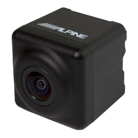
  9. Alpine HCE-C117D User manual

Alpine HCE-C117D User manual

Other manuals for HCE-C117D

1

Other Alpine Automobile Accessories manuals

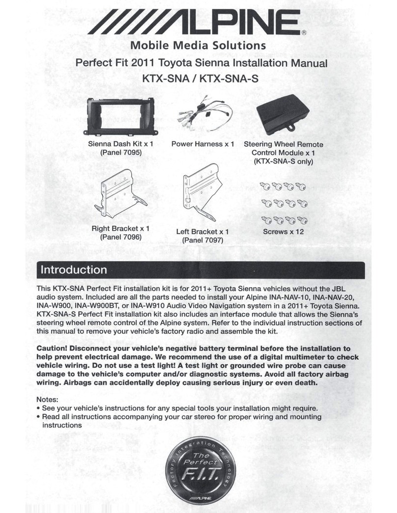
Alpine KTX-RV48-S User manual

Alpine

Alpine KTX-RV48-S User manual

Alpine i509-WRA-JL User manual

Alpine

Alpine i509-WRA-JL User manual

Alpine HCE-C157D User manual

Alpine

Alpine HCE-C157D User manual

Alpine KTX-TCM8-S User manual

Alpine

Alpine KTX-TCM8-S User manual

Alpine RSE-K100SC Manual

Alpine

Alpine RSE-K100SC Manual

Alpine DCS-BT1 User manual

Alpine

Alpine DCS-BT1 User manual

Alpine KTX-SNA-S User manual

Alpine

Alpine KTX-SNA-S User manual

Alpine KTX-WXE-M38 User manual

Alpine

Alpine KTX-WXE-M38 User manual

Alpine KTX-FPU8 User manual

Alpine

Alpine KTX-FPU8 User manual

Alpine HCE-C1100 User manual

Alpine

Alpine HCE-C1100 User manual

Alpine HCE-C300R User manual

Alpine

Alpine HCE-C300R User manual

Alpine KCE-400BT User manual

Alpine

Alpine KCE-400BT User manual

Alpine KTX-CMO User manual

Alpine

Alpine KTX-CMO User manual

Alpine IVE-W530 User manual

Alpine

Alpine IVE-W530 User manual

Alpine eX-10 Instruction Manual

Alpine

Alpine eX-10 Instruction Manual

Alpine ACTIVE VIEW HCE-C305R User manual

Alpine

Alpine ACTIVE VIEW HCE-C305R User manual

Alpine i509-WRA-JK User manual

Alpine

Alpine i509-WRA-JK User manual

Alpine HCE-C114 User manual

Alpine

Alpine HCE-C114 User manual

Alpine APF-V1G7 User manual

Alpine

Alpine APF-V1G7 User manual

Alpine RSE-K100TN User manual

Alpine

Alpine RSE-K100TN User manual

Alpine KTX-WXE-CA8 User manual

Alpine

Alpine KTX-WXE-CA8 User manual

Alpine X109-WRA User manual

Alpine

Alpine X109-WRA User manual

Alpine KIT-903DU-OEM User manual

Alpine

Alpine KIT-903DU-OEM User manual

Alpine INE-W928R User manual

Alpine

Alpine INE-W928R User manual

Popular Automobile Accessories manuals by other brands

Magneti Marelli AC161 Installation instruction

Magneti Marelli

Magneti Marelli AC161 Installation instruction

FDI uEZ GUI Start here

FDI

FDI uEZ GUI Start here

JCROffroad JT Install instructions

JCROffroad

JCROffroad JT Install instructions

Rostra VOXXElectronics 250-1930 owner's guide

Rostra

Rostra VOXXElectronics 250-1930 owner's guide

TOP VEHICLE TECH GR3FORD5 installation manual

TOP VEHICLE TECH

TOP VEHICLE TECH GR3FORD5 installation manual

Safe Fleet PRIME DESIGN AR-2000-BLK manual

Safe Fleet

Safe Fleet PRIME DESIGN AR-2000-BLK manual

Skoda Fabia Combi 5J Fitting instructions

Skoda

Skoda Fabia Combi 5J Fitting instructions

Camcar 40077 Al Mounting instructions

Camcar

Camcar 40077 Al Mounting instructions

Camcar 40089 AL Mounting instructions

Camcar

Camcar 40089 AL Mounting instructions

Impac Tradesman 2000 installation manual

Impac

Impac Tradesman 2000 installation manual

DVB OFFROAD BRSB-01 installation manual

DVB

DVB OFFROAD BRSB-01 installation manual

Safari Snorkel SS385HF installation guide

Safari Snorkel

Safari Snorkel SS385HF installation guide

ULTIMATE SPEED 279746 Assembly and Safety Advice

ULTIMATE SPEED

ULTIMATE SPEED 279746 Assembly and Safety Advice

SSV Works DF-F65 manual

SSV Works

SSV Works DF-F65 manual

ULTIMATE SPEED CARBON Assembly and Safety Advice

ULTIMATE SPEED

ULTIMATE SPEED CARBON Assembly and Safety Advice

Witter F174 Fitting instructions

Witter

Witter F174 Fitting instructions

WeatherTech No-Drill installation instructions

WeatherTech

WeatherTech No-Drill installation instructions

TAUBENREUTHER 1-336050 Installation instruction

TAUBENREUTHER

TAUBENREUTHER 1-336050 Installation instruction

manuals.online logo
manuals.online logoBrands
  • About & Mission
  • Contact us
  • Privacy Policy
  • Terms and Conditions

Copyright 2025 Manuals.Online. All Rights Reserved.

Direct Connection Rearview Camera
HCE-C117D
• OWNER'S MANUAL
Please read before using this equipment.
•
MODE
D,EMPLOI
Veuillez lire avant d,utiliser cet appareil.
• MANUAL DE OPERACION
Lealo antes de utilizar este equipo.
ALPINE ELECTRONICS MARKETING, INC.
1-1-8 Nishi Gotanda,
Shinagawa-ku,
Tokyo 141-0031, Japan
Phone 03-5496-8231
ALPINE ELECTRONICS OF AMERICA, INC.
19145 Gramercy Place, Torrance,
California 90501,
U.S.A.
Phone 1-800-ALPINE-1 (1-800-257-4631)
ALPINE ELECTRONICS OF
CANADA,
INC.
777 Supertest Road, Toronto,
Ontario
M3J
2M9, Canada
Phone 1-800-ALPINE-1 (1-800-257-4631)
YAMAGATA
Co.,
Ltd.
2-6-34, Takashima, Nishi-ku,Yokohama-shi,
Kanagawa, 220-8515 Japan
ALPINE ELECTRONICS OF AUSTRALIA PTY. LTD.
161-165 Princes Highway, Hallam
Victoria 3803, Australia
Phone 03-8787-1200
ALPINE ELECTRONICS
GmbH
Frankfurter Ring 117, 80807 Munchen, Germany
Phone 089-32 42 640
ALPINE ELECTRONICS OF U.K. LTD.
Alpine
House
Fletchamstead Highway, Coventry
CV4
9TW,
U.K.
Phone 0870-33
33
763
ALPINE ELECTRONICS FRANCE S.A.R.L.
(RCS
PONTOISE
B338
101
280)
98,
Rue
de
Ia
Belle Etoile, Z.l. Paris Nord
II,
B.P.
50016,95945 Roissy Charles
de
Gaulle
Cedex, France
Phone 01-48638989
ALPINE
ITALIA
S.p.A.
Vi
ale
C.
Colombo
8,
20090Trezza
no
Sui
Naviglio (MI), Italy
Phone 02-484781
ALPINE ELECTRONICS DE ESPANA, S.A.
Portal
de
Gamarra 36, Pabell6n, 32
01013 Vitoria (Aiava)-APDO 133, Spain
Phone 945-283588
ALPINE ELECTRONICS (BENELUX)
GmbH
Leuvensesteenweg
51
O-B6,
1930Zaventem, Belgium
Phone 02-725-13
15
Designed
by
ALPINE Japan
Printed in Japan (Y)
68-13530Z84-A
Operating Instructions
English
it
wARNING
This symbol means
important
instructions. Failure
to
heed
them
can
result in serious injury
or
death.
WHEN
USING
A
CAMERA
SYSTEM,
THE
DRIVER
MUST
VISUALLY
CHECK
ACTUAL
CONDITIONS AROUND
THE
VEHICLE.
MAKE
SURE
THERE
ARE
NO
PERSONS
OR
ANIMALS IN
THE
AREA
IN WHICH
YOU
ARE
MANEUVERING
OTHERWISE
YOU
COULD
INJURE
THEM.
A camera assists the driver by sending images to the screen
showing conditions in view
of
the camera. The camera
uses a wide-angle lens, therefore, there
is
a difference in
distance perspective between what is normally seen and
what appears on the screen. Also, the images shown by the
rearview camera are reversed, so as to appear the same as
what is seen through the rearview mirror.
The camera may
not
perform to full capability due to
variables such
as:
• weather conditions such as hard rain, snow, fog
or
mud
• extremely high
or
low temperatures near camera
• slope
of
vehicle and/
or
roadway
• direct exposure to very bright light such as headlamp
or
bright
sunlight
• moving from very dark to very bright light
and
vice versa such
as in parking garages or tunnels
• extremely low light areas
• walls
or
objects that are located diagonally in relation to the
camera
• retracted mirrors that change camera viewing angle
• open doors
or
trunks
• changes to height
of
vehicle due to loading capacity
or
hydraulic
suspensions
• obstacles located at the corner
of
the vehicle
DO
NOT
DISASSEMBLE
OR
ALTER.
Doing so may result in an accident, fire
or
electric shock.
KEEP
SMALL
OBJECTS
SUCH
AS
BOLTS
OR
SCREWS
OUT
OF
THE
REACH
OF
CHILDREN.
Swallowing them may result
in
serious injury.
If
swallowed,
consult a physician immediately.
USE
THE
CORRECT
AMPERE
RATING
WHEN
REPLACING
FUSES.
Failure to do so may result in fire
or
electric shock.
USE
ONLY
IN
CARS
WITH A 12
VOLT
NEGATIVE
GROUND.
(Check with your dealer
if
you are
not
sure.) Failure to do
so may result in fire, etc.
BEFORE
WIRING,
DISCONNECT
THE
CABLE
FROM
THE
NEGATIVE
BATTERY
TERMINAL.
Failure to do so may result in electric shock
or
injury due
to electrical shorts.
DO
NOT
USE
BOLTS
OR
NUTS
IN
THE
BRAKE
OR
STEERING
SYSTEMS
TO
MAKE
GROUND
CONNECTIONS.
Bolts
or
nuts used for the brake
or
steering systems (or any
other safety-related system), or tanks should NEVER be
used for installations
or
ground connections. Using such
parts could disable control
of
the vehicle and cause fire etc.
DO
NOT
DAMAGE
PIPE
OR
WIRING
WHEN
DRILLING
HOLES.
When drilling holes in the chassis for installation, take
precautions so
as
not
to contact, damage or obstruct pipes,
fuel lines, tanks
or
electrical wiring. Failure to take such
precautions may result in fire.
MINIMIZE
DISPLAY
VIEWING
WHILE
DRIVING.
Viewing the display may distract the driver from looking
ahead
of
the vehicle and cause an accident.
DO
NOT
SPLICE
INTO
ELECTRICAL
CABLES.
Never cut away cable insulation to supply power to other
equipment. Doing so will exceed the current carrying
capacity
of
the wire
and
result in fire
or
electric shock.
DO
NOT
INSTALL
IN
LOCATIONS
WHICH MIGHT
HINDER
VEHICLE
OPERATION,
SUCH
AS
THE
STEERING
WHEEL
OR
GEARSHIFT.
Doing so may obstruct forward vision
or
hamper
movement etc.
and
results in serious accident.
DO
NOT
ALLOW
CABLES
TO
BECOME
ENTANGLED
IN
SURROUNDING
OBJECTS.
Arrange wiring and cables in compliance with the manual
to prevent obstructions when driving. Cables or wiring that
obstruct
or
hang up
on
places such as the steering wheel,
gear lever, brake pedals, etc. can be extremely hazardous.
DO
NOT
ROUTE
ELECTRICAL
CABLES
NEAR
HOT
OR
MOVING
PARTS
Route the cables
and
wiring away from hot
or
moving
parts,
and
fix
them
securely to avoid heat/mechanical
damage to the cable insulation, which may result in
shortcircuit, fire
or
electric shock.
MAKE
THE
CORRECT
CONNECTIONS.
When making connections to the vehicle's electrical
system, be aware
of
the factory installed components (e.g.
on-board computer).
Do
not
tap into these leads to provide
power for this unit.
When
connecting the device to the
fuse box, make sure the fuse for the intended circuit
of
the device has the appropriate amperage. Failure to do so
may result in fire
or
damage to the unit and/
or
the vehicle.
When in doubt, consult your Alpine dealer.
USE
THIS
PRODUCT
FOR
MOBILE 12
VOLT
APPLICATIONS.
Use for other than its designed application may result in
fire, electric shock
or
other injury.
CHECK
THAT
THE
CAMERA
MOUNTINGS
IS
ATTACHED
SECURELY,
AND
THAT
THE
SCREWS
ARE
TIGHT
BEFORE
DRIVING.
Failure to do so may result in an accident.
WHEN
INSTALLING
OR
CHECKING
A
CAMERA,
DO
SO
AFTER
PARKING
THE
CAR
IN A
LEVEL,
SAFE
PLACE,
TURNING
OFF
THE
ENGINE,
AND
APPLYING
THE
HAND
BRAKE.
Failure to do so may result in an accident.
WHEN
USING
A
DRILL
TO
MAKE
A
HOLE,
TAKE
PRECAUTIONS
SUCH
AS
WEARING
GOGGLES
SO
FRAGMENTS
DO
NOT
GET
INTO
THE
EYES.
Failure to do so may result in injury.
~CAUTION
This symbol means
important
instructions. Failure
to
heed them can
result in injuryor material property
damage.
HAVE
THE
WIRING AND
INSTALLATION
DONE
BY
EXPERTS.
The wiring and installation
of
this unit requires special
technical skill and experience.
To
ensure safety, always
contact the dealer where you purchased this product to
have the work done.
ARRANGE
THE
WIRING
SO
IT
IS
NOT
CRIMPED
OR
PINCHED
BY
A
SHARP
METAL
EDGE.
Route the cables and wiring away from moving parts (like
the seat rails)
or
sharp
or
pointed edges. This will prevent
crimping and damage to the wiring.
USE
SPECIFIED
ACCESSORY
PARTS
AND
INSTALL
THEM
SECURELY.
Be
sure to use only the specified accessory parts. Use
of
other than designated parts may damage this unit
internally
or
may not securely install the unit in place. This
may cause parts to become loose resulting in hazards
or
product failure.
CONNECT
LEADS
PROPERLY
Be
sure to connect the color coded leads according to
the diagram. Incorrect connections may cause the unit
to malfunction
or
cause damage to the vehicle's electrical
system.
HALT
USE
IMMEDIATELY
IF
A
PROBLEM
APPEARS.
Failure to do so may cause personal injury
or
damage to
the product. Return it to your authorized Alpine dealer
or
the nearest Alpine Service Center for repairing.
EXCEPT
FOR
THE
CAMERA,
DO
NOT
ATTACH
ANY
PARTS
TO
AREAS
WHICH
WILL
GET
WET,
OR
WHERE
THERE
IS
A
LOT
OF
HUMIDITY
OR
DUST.
Failure to do so may result in fire
or
damage.
DO
NOT
ATTACH
THE
CAMERA
MOUNTING
TO
FLUOROCARBON
RESIN
FINISHED
CAR
BODIES
OR
GLASS.
Doing so could cause the strength
of
the camera mounting
to weaken, which could cause it to
fall
of
and cause
accidents, injury,
or
damage to the car body.
DO
NOT
ATTACH
THE
CAMERA
MOUNTING
TO
ANY
SURFACE
WHERE
THE
ENTIRE
ADHESIVE
SURFACE
CANNOT
BE
APPLIED.
Doing so could cause the strength
of
the camera mounting
to weaken, which could cause it to
fall
of
and cause
accidents, injury,
or
damage to the car body.
NOTICE
•
About
Care
of
Device
Do not assert any excess pressure to the camera
or
the
mounting,
as
this could cause the camera direction to shift, or
the camera mounting bracket to come off.
•
To
prevent the camera lens, mounting and cords from changing
color
or
shape,
or
from deteriorating, wipe with a chemical-free,
damp cloth.
•
When
washing the car, do not using an automatic car washer,
or
high-pressure washer. Doing so could cause the camera to come
off, damage to the device cord,
or
may allow water to enter the
camera or the inside
of
the car.
• In some cases, to attach the device, a hole must be drilled in the
car body, requiring use
of
touch-up paint (retail product) for
rust-prevention, and should be prepared beforehand.
•
Be
sure to disconnect the cable from the
(-)
battery post before
installing your
HCE-Cll7D.
This will reduce any chance
of
damage to the unit in case
of
a short-circuit.
•
Be
sure to connect the color coded leads according to the
diagram. Incorrect connections may cause the unit to
malfunction
or
damage to the vehicle's electrical system.
• When making connections to the vehicle's electrical system,
be aware
of
the factory installed components (e.g. on-board
computer). Do not tap into these leads to provide power for this
unit. When connecting the
HCE-Cll7D
to the fuse box, make
sure the fuse for the intended circuit
of
the
HCE-Cll7D
has the
appropriate amperage. Failure to do so may result in damage to
the unit and/or the vehicle. When in doubt, consult your Alpine
dealer.
• About Rear Camera
The rear camera
of
this camera system
is
a dedicated product.
Do not connect it to other cameras.
• About Power Connection
Connect a reverse input cable (orange/white) to the power cable
of
the rear lamp. For details, consult a dealer purchased camera,
or car dealer. Connect this to a power cable
of
the rear lamp, but
not to the positive
of
the rear lamp signal cable.
•
Do
not
use mobile phones and wireless devices near the
camera.
• Doing so may result in noise on the screen
or
malfunction. It
is
recommended to use mobile phones
or
wireless devices away
from the camera.
• About Camera Installation Location
Before installing, make sure there
is
a enough space to be able
to install the camera. Ifpossible, install the camera in the center
of
the bumper or other fitting. Ifthe camera
is
installed at a
distance left or right
of
center, the image may differ from the
real
view.
• Confirming the Display Function
To
connect the unit, confirm that the monitor will require a
compatible
RCA
pin jack.
lnstallation/lnstallation/lnstalacion
G)
Rearview Camera
G)
Camera
de
recul
G)
Camara
de
marcha
atras
®
Camera extension cable
(10.5m}
@ Rallonge cable
camera
(10,5m}
®
Cable
de
extension
de
Ia
camera
(1
O,Sm}
x4
®Self-tapping
screw
®
Vis
autotaraudeuse
® Tornillo macho roscador
®
Camera
mounting
bracket
®
Support
de
fixation
®
Soporte
de
Ia
camara
®
Waterproofing
pad
@
Protege
cable
etanche
®
Dispositivo
protector
resistente
al
agua
@)
Heat-shrinkTube
@)
Tube
thermoretractable
@)
Tubo termorretractil
x2
@ Hexscrew
@
Vis
hexagonale
@ Tornillo hexagonal
I
0
Waterproofing
pad
adhesive
sheet
0
Adhesif
pour
protege
cable
etanche
0
Hoja adhesiva
para
el
dispositivo
protector
resistente
al
agua
\
@ Camera
mounting
bracket
for
KTX-C1
OLP
@
Support
de
fixation
de
Ia
camera
pour
KTX-C1
OLP
@
Soporte
de
montaje
de
Ia
camara
para
KTX-
C10LP
QD
Hexagonalwrench
QD
Cle6pans
QD
Llave hexagonal
®Wire
clamp
® Attachefils
® Fijador
de
cables
xS
Install
the
Camera on
the
Rear Bumper{lnstallez Ia
camera sur Ia carrosserje arrji:reflnstaladOn en el
acabado trasero
Fig.l!Schema 1/Fig.l
Fig.2/Schema 2/Fig.2 Fig.3/Schema 3/Fig.3
English
Attach
the
camera
to
the
camera
mounting
bracket
®.Pull
the camera cable
through
to
the
camera
mounting
bracket@,
and secure
with
the
hex screws
@
(see
Fig.
2).
2 Loosen
the
camera
mounting
bracket®
and angle
adjustment screw. Determine
the
attachment angle,
and carefully
tighten
the
angle adjustment screw.
3 Make a
13
mm
hole in
the
rear
bumper
camera
mounting
bracket
(see
Fig.
3).
4 Pull
the
camera cable inside
the
car
through
the
hole
made in step
3.
5
Peel
off
the
adhesive
seal
from
the
camera
mounting
bracket and attach
the
camera
mounting
bracket on
the
chassis
of
the
vehicle.
If
required, fix
the
camera
mounting
bracket using self-tapping screws.
• Attach
the
camera
in
aposition
where
it
does
not
touch
the
number
plate.
•
Use
retail
touch-up paint
to
paint
the
surface
and
surrounding
area
when a
hole
has
been
made
in
a metal
surface.
•
Make
sure
water cannot enter
the
hole
madefor
the
camera
cable.
Use
commercially
available
waterproof
tape
or
sealant.
• If
necessary,
use
a self-tapping
screw®
to
fix
the
camera
mounting bracket
(In
the
case
of
aplastic mount
area).
Fran~ais
Fixez
Ia
camera sur le
support@.
Passez
le
cable de
Ia
camera dans le
support@,
puis fixez-le a!'aide des vis
hexagonaux@
(schema
2).
2 Deserrez
le
support
de
Ia
camera®
et
inserez en
angle
Ia
vis de reglage. Choisissez I'
angle de fixation,
puis reserrez delicatement
Ia
vis dans cet angle.
3 Faites un
trou
de
13
mm
dans
Ia
carrosserie arriere
pour
fixer le supportde
Ia
camera (schema
3).
4 Faites passer le cable de
Ia
camera
a
l'interieur
du
vehicule par le trou fait
a
l'etape
3.
5 Retirez le film protecteur du support
de
Ia
camera,
puis fixez
ce
dernier sur
le
chassis
du
vehicule.
Le
cas
echeant, fixez le
support
a
l'aide des vis
autotaraudeuses.
• Fixez
la
camera
de
fa~on
a
ce
qu
'elle
ne
touche
pas
la
plaque d'immatriculation.
•
Si
vous
avez
perce
un
trou
dans
une
surface metallique,
une
retouche
est
necessaire
sur et autour
de
la
surface
avec
une peinture
speciale.
Le
trou
permettant
de
faire
passer
le
cable
de
la
camera
do
it
etre
impermeable.
Utilisez
pour
cela
du
ruban adhesif
impermeable
ou
un
produit detancheite vendu
dans
le
commerce.
•
Si
besoin
est,
utilisez
une
vis
autotaraudeuse
®
pour
fixer
le
support
de
la
camera
(notamment
si
la
surface
de
montage
est
en
plastique).
Espanol
Coloque
Ia
camara
en
el
soporte de
Ia
camara
®.
Tire del cable de
Ia
camara atraves del soporte de
Ia
camara ® y ffjelo con los tornillos
hexagonales@
(vease
Ia
figura
2).
2 Afloje
el
soporte de
Ia
camara ® e inserte en angulo
el
tornillo
de ajuste. Calcule
el
angulo
de
fijaci6n
y,
con cuidado, apriete
el
tornillo
en dicho angulo.
3
Real
ice un agujero de
13
mm
en
el
soporte de
Ia
camara del acabado trasero (vease
Ia
figura
3).
4 Tire del cable de
Ia
camara desde
el
interiordel coche
atraves
el
agujero del paso
3.
5 Retire
el
sello adhesivo del soporte de
Ia
camara y
ffjelo
en
el
chasis del vehfculo.
Si
fuera necesario, fije
el
soporte de
Ia
camera con ayuda de los tornillos
embriados suministrados.
•
Coloque
la
camara
en
una
posicion
en
la
que
no
toque
la
matricula.
•
Utilice
pintura
para
retocar
la
superficie y
el
area
que
rodea
el
agujero
realizado
en
la
superficie
de
metal.
•
Es
importante
que
no
entre
agua
en
el
orificio
del
cable
de
la
camara.
Utilice
cinta adhesiva
resistente
al
agua
o un
sellador.
•
Si
es
necesario,
utilice
un
tornillo
macho
roscador
®
para
fijar
el
soporte
de
la
camara
(en
caso
de
que
el
area
de
instalaci6n
sea
de
plastico
).
Conpectjops/Raccordemepts/Copexjopes
HCE-C117D-compatible Alpine
AV
Head
Unit*/
Unite principale
AV
Alpine compatible avec
HCE-C117D*/
Unidad principal
AV
de Alpine compatible
con
el HCE-C117D*
i
Camera extension cable (supplied)/
Rallonge cable camera (fournie)/
Cable
de
extensi6n
de
Ia camera (suministrada)
Rearview Camera/
Camera
de
recul/
L Camara
de
marcha atras
~~
Fig.4/Schema 4/Fig.4
English
•
For
details
on
connection,
refer
to
the
installation manual
of
the
HCE-C117D-compatible product. Connect
the
rear
camera
input connector
only.
* This product
can
only connect
to
Alpine Mobile Media
Stations
with
the dedicated Alpine camera input.
For
information on HCE-C1170-compatible products,
contact your local authorized Alpine dealer or visit the
Alpine America
home
page (http://www.alpine-usa.
com).
Fran~ais
•
Pour
plus
de
details
sur
la
connexion, consultez
le
guide
d'installation
du
produit compatible
avec
HCE-C117D.
Raccordez
uniquement
la
borne
d'entree
de
la
camera
arriere.
* Cet appareil ne peut etre raccorde qu'a une station
multimedia portable Alpine
via
Ia
borne d'entree de
Ia
camera Alpine. Pour plus d'informations sur
les
produits compatibles avec HCE-C1170, contactez votre
revendeur Alpine ou visitez
Ia
page d'accueil du site Web
Alpine America (http://www.alpine-usa.com).
Espanol
•
Para
obtener mas informacion
acerca
de
la
conexion,
consulte
el
manual
de
instalacion
del
producto compatible
con
el
HCE-C117D.
Conecte
unicamente
el
conector
de
entrada
de
la
camara
de
vision
trasera.
*
Este
producto
solo puede conectarse a equipos Mobile
Media de Alpine con una entrada exclusiva de c3mara
de Alpine.
Para
obtener
mas
informacion acerca de
los
productos compatibles con
el
HCE-C1170, pongase en
contacto con
su
distribuidor Alpine autorizado o visite
Ia
pagina principal de Alpine America
(http://www.
alpineusa. com).
Adjustjnq
the
Camera Anqle/R@qlaqe
de
I'
angle
de
Ia
cam@ra/Ajyste del
lnqylo
de
Ia
c;imara
II
Fig.5/Schema 5/Fig.S
Fig.7
/Schema
7/Fig.7
Fig.6/Schema 6/Fig.6
English
&caution
When adjusting
the
camera
angle,
do
so
after
turning
off
the
engine
and
applying
the
hand
brake
to
avoid
an
accident.
Put
the
gear shift
into
reverse
(R),
and check
the
image
from
the
camera on
the
display.
2 Loosen
the
camera
mounting
bracket®
and angle
adjustment screw. Determine
the
camera angle, and
carefully
tighten
the
angle adjustment screw.
Fran~ais
&Attention
Veillez a
COUper
le
moteur
eta
mettre
le frein a main
avant
de
regler
I'
angle
de
Ia
camera
afin d'eviter
tout
accident.
Mettez
le
levier de vitesse en marche arriere
(R),
puis
verifiez l'image de
Ia
camera affichee al'ecran.
2 Deserrez
le
support
de
Ia
camera®
et
inserez en
angle
Ia
vis de reglage. Choisissez l'angle de
Ia
camera,
puis reserrez delicatement
Ia
vis dans l'angle.
Espariol
& Precaucion
Cuando
ajuste
el
lngulo
de
Ia
clmara,
apague
primero
el
motor
y
ponga
el
freno
de
mano
para
evitar posibles
accidentes.
Ponga
Ia
palanca de marchas en marcha atras
(R)
y
compruebe
Ia
imagen de
Ia
camara que
se
muestra
en
Ia
pantalla.
2 Afloje
el
soporte de
Ia
camara ® e inserte
en
angulo
el
tornillo
de ajuste. Calcule
el
angulo de
Ia
camara
y,
con cuidado, apriete
el
tornillo
en dicho angulo.
Securjna
the
Camera Cable/Fjxatjon du
cible
de
Ia
camera/Fjjad6n del cable
de
Ia
clmara
(A) Rearview camera/Camera arriere/Camera trasera
(B)
To
HCE-Cll7D-compatible product/Vers le
produit
compatibleavec HCE-
CI17D/
AI
producto compatible con el
HCE-Cll7D
(C)
Clam
per/
Attache-fils/Fijador
(D) Waterproofing pad/Protege-cables impermeable/Dispositivo protector
resistente al agua
Fig. 8/Schema8/Fig. 8
English
Secure the camera cable while referring
to
Fig.
8.
Attach the waterproofpad ®
with
the
waterproof
pad adhesive sheet
(J),
and secure any slack cable
around the waterproof
pad®
using
the
wire clamp
@.
•
Ensure
the
cable
does
notget caught
in
the trunk,
rear
door(s)
or
any
hinges.
•
The
cable
should
go
on
the
outside
of
car
hinges
and
harness
covers.
• After completing
wiring,
open
and
close
the
trunk and
the
rear
doors
several
times
to
confirm
the
cable
is
notgetting
caught
or
rubbing anywhere.
Francrais
Fixez
le cable de
Ia
camera en vous reportant
au
schema
8.
Fixez le
protege-cables®
sur son ruban adhesif
(J),
puis fixez
et
tendez
le
cable sortant du protege-cables
® al'aide de !'attache-fils@.
• Assurez-vous
que
le
cable
n'est
pas
coince
dans
la
malle,
dans
les
partes
arrieres
ou
dans une
charniere.
•
Le
cable
doit
etre
hors
des
protections
des
charnieres
et
des
harnais.
•
Une
fois
le
cablage
termine, ouvrez et refermez plusieurs
fois
la
malle
arriere
et
les
partes
arrieres
afin
de
vous
assurez
que
le
cable
n'est
pas
coince
et qu'il
ne
subit aucun
frottement.
Espanol
Fije
el
cable de
Ia
camara siguiendo
el
diagrama de
Ia
figura
8.
Coloque
el
dispositive protector resistente
al
agua
® con
Ia
hoja adhesiva correspondiente
(J)
y
fije cualquier cable que sobresalga alrededor del
dispositivo resistente
al
agua ® con ayuda del fijador
de
cables@.
• Verifique
que
el
cable
no
queda atrapado
en
el
maletero,
las
puertas
traseras
o
en
cualquier
bisagra.
•
El
cable
debe
estar
fuera
de
las
protecciones
de
las
bisagras
y
arneses
del
vehiculo.
Una
vezfinalizado
el
cableado,
abra
y
cierre
el
maletero
y
las
puertas
traseras
varias
veces
para
com
pro
bar
que
el
cable
no
queda atrapado ni
plegado
en
ningun
sitio.
When usjnq KJX-Cl
OLP
(License
plate
Moyntjnq
Kjt
for
RearyjewCameral
CSold
seoaratelyl
for
jnstallatjon/Sj
ytiliza
el
modelo
KTX-Cl
OLP
Ckjt
de
montaje
de
matricyla
para
cimara
traseral
Cse
yende
por
separadol para Ia
jnstalad6n/
Lors
de
l'ytilisatjon
dy
kjt
KTX-Cl
OLP
Ckjt
d'jnstallatjon
de
Ia
plaqye
d'jmmatrjcylatjon
poyr
Ia camera
de
recull
Cyendu
separement)
pour
l'jnstallatjon
J
*A
Fig.9/Schema 9/Fig.9
!
b
r
*A
*B
Fig.lO/Schema 10/Fig.lO
@ Camera
bracket
(included}/
@
Support
de
Ia camera
(fourni}/
@
Soporte
de
cimara
(incluido)
*A
Screw
with
spring
washer
(included
with
KTX-Cl
OLP)
x4/
*A
Vis avec
rondelle
(fourni
avec
le
KTX-Cl
OLP)
x4/
*A
Tornillocon arandela
(incluido
con el KTX-C10LP)
x4
*B
Base
bracket
(included
with
KTX-C1
OLP}/
*B
Support
de
base
(fourni
avec le KTX-C10LP}/
*B
Soporte
de
base
(incluido
con el
KTX-C1
OLP)
English
Install
the
camera
on
the
License plate
frame
with
the
camera
bracket@
(included) and *A, B(included
with
KTX-Cl
OLP).
(Fig.9/Fig.1
0)
•
For
details
on
how
to
install
the
camera
on
the
License
plateframe,
refer
to
the
KTX-ClOLP Installation Manual.
~Caution
•
Be
sure
to
install
the
camera
on
the
License
plate
frame
with
its
ALPINE
logo
up.
Fran-;:ais
lnstallez
Ia
camera sur le cadre
de
Ia
plaque
d'immatriculation
avec le
support
de
Ia
camera@
(fourni)
et
*A, B(fournis avec le KTX-Cl
OLP).
(Fig.9/Fig.1
0)
• Pour plus
de
details sur !'installation
de
la
camera
sur
le
cadre
de
la
plaque d'immatriculation, consultez
le
guide
d'installation
du
KTX-ClOLP.
~Attention
• Veillez
a
installer
Ia camera sur lecadre
de
Ia
plaque
d'immatriculation
en
dirigeant
le
logo
ALPINE vers
le
haut.
Espanol
lnstale
Ia
camara en el
bastidor
de
Ia
matrfcula con el
soporte
de
camara@
(incluido) y*A, B
(incluido
con el
KTX-Cl
OLP).
(Fig. 9/Fig. 1
0)
•
Para
obtener mas informacion
sabre
la
instalaci6n
de
la
camara
en
el
bastidor
de
la
matricula, consulte
al
manual
de
instalaci6n
del
KTX-ClOLP.
~
Precaucion
•
Es
muy
importante
instalar
Ia
cimara
en el
bastidor
de
Ia
matricula
con
ellogotipo
de
ALPINE hacia
arriba.