I
Installing The Alpine Head Unit (Continued)
5.
Connect
the
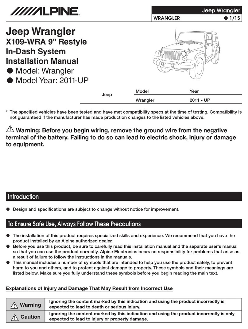
Yellow/Black
foot
brake
wire
to
the
Blue
with
Silver
dots
wire
at
the
foot
brake in
the
vehicle. It
is located
right
at
the
brake
switch.
This wire will
show
+
12V
when
the
brake
is pressed.
6.
Connect
the
Yellow/Blue parking brake
wire
to
the
Red/White wire
at
the
parking brake. It's
located
high
in
the
drivers
kick
panel behind
the
parking brake.
This wire will
go
to
ground
when
the
parking
brake
is
engaged.
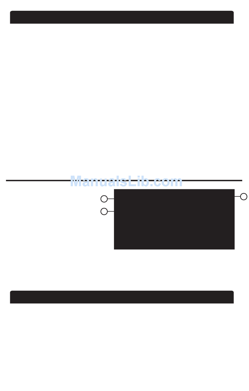
Wiring Harness Diagram
To Steering Wheel Remote
Control
Module
Liability Disclaimer
Yellow/Blue
To
Parking
Brake
Red/
White
(-)
at
the
parking
brake in drivers
kick
panel
To
Foot
Brake
Blue
w/
Silver
dots(+)
at
switch
~..;..;,;,_:~~
above
pedal
*
No
connection
for
INA-W910;
To
Toyota Sienna
Vehicle Harness
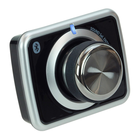
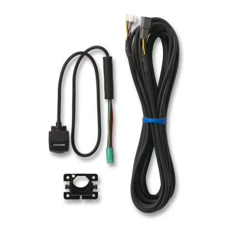
Bluetooth®
module
optional
for
INA-W900;
KCE-250BT
module
included
with
the
INA-W900BT.
Due
to
changes
in design
and
manufacturing
that
may
occur
with
your
specific
vehicle,
it
is
important
that
you
do
not
rely solely
on
vehicle information contained in
this
installation
manual,
such
as
dash
disassembly, wire harness, and
codes.
Such information
should
be
confirmed
with
the
vehicle manufacturer. Alpine Electronics, Inc. and
its
affiliated
companies
is
not
responsible
for
damage
that
may
occur
to
you
or
your
automobile
during
the
installation
of
the
Perfect
Fit
Kit.
If
you
have
any
further
questions, feel free
to
contact
Alpine
Tech
Support
at
1-800-NAV-HELP.
ALPINE
ELECTRONICS
OF
AMERICA,
INC., 19145 Gramercy Place, Torrance,
CA
90501, U.S.A
ALPINE
ELECTRONICS
OF
CANADA,
INC.,
777
Supertest
Road, Toronto, Ontario
M3J
2M9,
Canada
Do
not
send
products
to
these addresses.
Call
the
toll
free
number
or
visit
the
website
to
locate
a service center.
