manuals.online logo
Brands
  1. Home
  2. •
  3. Brands
  4. •
  5. Amana
  6. •
  7. Air Conditioner
  8. •
  9. Amana AAC101SRA Service Manual

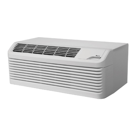
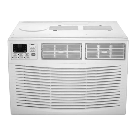
Amana AAC101SRA Service Manual

This manual suits for next models

1

Other Amana Air Conditioner manuals

Amana AP095R User manual

Amana

Amana AP095R User manual

Amana Thru-wall User manual

Amana

Amana Thru-wall User manual

Amana AP076E User manual

Amana

Amana AP076E User manual

Amana AP125D User manual

Amana

Amana AP125D User manual

Amana MBVC Series Service manual

Amana

Amana MBVC Series Service manual

Amana PBE093B35MB Quick start guide

Amana

Amana PBE093B35MB Quick start guide

Amana ASX14 User manual

Amana

Amana ASX14 User manual

Amana AAC081SRA Service Manual

Amana

Amana AAC081SRA Service Manual

Amana PTC073E00AXXXAB Owner's manual

Amana

Amana PTC073E00AXXXAB Owner's manual

Amana PGA**C User manual

Amana

Amana PGA**C User manual

Amana ACD10KE User manual

Amana

Amana ACD10KE User manual

Amana Quiet Zone Room Air Conditioner User manual

Amana

Amana Quiet Zone Room Air Conditioner User manual

Amana AMA05KF User manual

Amana

Amana AMA05KF User manual

Amana ACE15KE User manual

Amana

Amana ACE15KE User manual

Amana DigiSmart PTC073G***XXX Installation instructions

Amana

Amana DigiSmart PTC073G***XXX Installation instructions

Amana PBC123B00MB Quick start guide

Amana

Amana PBC123B00MB Quick start guide

Amana RSC Ultron User manual

Amana

Amana RSC Ultron User manual

Amana 10c5ez Assembly instructions

Amana

Amana 10c5ez Assembly instructions

Amana ACD105E User manual

Amana

Amana ACD105E User manual

Amana REMOTE CONDENSING UNIT Guide

Amana

Amana REMOTE CONDENSING UNIT Guide

Amana ACE15JE User manual

Amana

Amana ACE15JE User manual

Amana distinctions DCP073A25AA User manual

Amana

Amana distinctions DCP073A25AA User manual

Amana CT-DPTAC Manual

Amana

Amana CT-DPTAC Manual

Amana PCA24C02E Manual

Amana

Amana PCA24C02E Manual

Popular Air Conditioner manuals by other brands

Fujitsu ASYG 09 LLCA installation manual

Fujitsu

Fujitsu ASYG 09 LLCA installation manual

York HVHC 07-12DS Installation & owner's manual

York

York HVHC 07-12DS Installation & owner's manual

Carrier Fan Coil 42B Installation, operation and maintenance manual

Carrier

Carrier Fan Coil 42B Installation, operation and maintenance manual

intensity IDUFCI60KC-3 installation manual

intensity

intensity IDUFCI60KC-3 installation manual

Frigidaire FAC064K7A2 Factory parts catalog

Frigidaire

Frigidaire FAC064K7A2 Factory parts catalog

Sanyo KS2432 instruction manual

Sanyo

Sanyo KS2432 instruction manual

LG MultiV Series installation manual

LG

LG MultiV Series installation manual

CLIMAVENETA a-CHD U-2T 606+2209 OPERATING AND INSTALLATION Manual

CLIMAVENETA

CLIMAVENETA a-CHD U-2T 606+2209 OPERATING AND INSTALLATION Manual

Midea EWK06CW5 user manual

Midea

Midea EWK06CW5 user manual

Pioneer FAB Series installation manual

Pioneer

Pioneer FAB Series installation manual

SPT WA-1511S user manual

SPT

SPT WA-1511S user manual

Mitsubishi Electric Mr.Slim MSZ-A24NA operating instructions

Mitsubishi Electric

Mitsubishi Electric Mr.Slim MSZ-A24NA operating instructions

Mitsubishi Electric PUHZ-RP50VHA4 Service manual

Mitsubishi Electric

Mitsubishi Electric PUHZ-RP50VHA4 Service manual

Panasonic CS-S18HKQ Service manual

Panasonic

Panasonic CS-S18HKQ Service manual

Panasonic CS-E15NKE3 operating instructions

Panasonic

Panasonic CS-E15NKE3 operating instructions

Gree GWH18TC-K3DNA1B/I Service manual

Gree

Gree GWH18TC-K3DNA1B/I Service manual

Friedrich ZoneAire Compact P08SA owner's manual

Friedrich

Friedrich ZoneAire Compact P08SA owner's manual

Daikin R32 Split Series installation manual

Daikin

Daikin R32 Split Series installation manual

manuals.online logo
manuals.online logoBrands
  • About & Mission
  • Contact us
  • Privacy Policy
  • Terms and Conditions

Copyright 2025 Manuals.Online. All Rights Reserved.

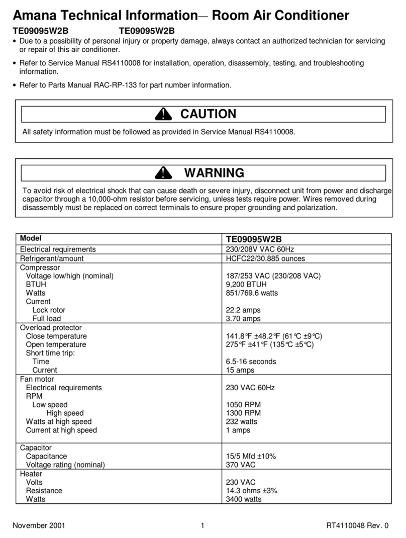
Amana Technical Information—Room Air Conditioner
December 2002 16022064
(Replaces RT4110056 Rev. 0)
1
AAC101SRA PAAC101SRA0
• Due to a possibility of personal injury or property damage, always contact an authorized technician for servicing or
repair of this air conditioner.
• Refer to Service Manual 16022061 for installation, operation, disassembly, testing, and troubleshooting
information.
• Refer to Parts Reference material for part number information.
CAUTION
!
All safety information must be followed as provided in Service Manual 16022061.
!WARNING
To avoid risk of electrical shock that can cause death or severe injury, disconnect unit from power and discharge
capacitor through a 10,000-ohm resistor before servicing, unless tests require power. Wires removed during
disassembly must be replaced on correct terminals to ensure proper grounding and polarization.
Model AAC101SRA
Electrical requirements 115 VAC 60Hz
Refrigerant/amount R22/30 ounces
Compressor
Voltage low/high (nominal)
BTUH
98/132 VAC (115 VAC)
10,735 BTUH
Watts 1000 watts
Current
Lock rotor
Full load
54 amps
8.8 amps
Overload protector External
Fan motor
Electrical requirements
RPM
Low speed
Med speed
High speed
Watts at high speed
Current at high speed
115 VAC 60Hz
730 RPM
830 RPM
1000 RPM
97 watts
2.1 amps
Compressor Capacitor
Capacitance
Voltage rating (nominal)
45 Mfd ±10%
250 V
Fan Motor Capacitor
Capacitance
Voltage rating (nominal)
8Mfd±5%
450 V
https://appliancetechmanuals.com
Component Specifications
16022064 December 2002
(Replaces RT4110056 Rev. 0)
2
!WARNING
To avoid risk of electrical shock that can cause death or severe injury, disconnect unit from power and
discharge capacitor through a 10,000-ohm resistor before servicing, unless tests require power. Wires removed
during disassembly must be replaced on correct terminals to ensure proper grounding and polarization.
Illustration Component Test Procedure Results
Compressor Check resistance of compressor windings:
Attach ohmmeter between winding C and S:
Attach ohmmeter between winding C and R:
Check compressor for grounds:
Attach one ohmmeter lead to compressor
case. Attach second ohmmeter lead to C,
then S, then R terminals on compressor:
NOTE: See Testing Procedures section of Service Manual
for additional compressor information.
Ohmmeter should indicate resistance
between windings.
Ohmmeter should indicate resistance
between windings.
Ohmmeter should indicate infinity on each
terminal.
Compressor
overload
Continuity
Ensure temperature of overload is at room temp.
Check continuity across leads: Overload should have continuity.
Compressor
Capacitor
Resistance (highest scale), with power removed.
Discharge capacitor and disconnect all attached wires.
Attach Analog ohmmeter leads between C terminal
and H terminal on capacitor:
Reverse leads on C and H terminals:
Check capacitor for ground.
Attach one ohmmeter lead to capacitor
case. Attach second ohmmeter lead to C,
then H terminals on capacitor:
Indicator swings to zero and slowly returns
toward infinity.
Indicator swings to zero and slowly returns
toward infinity.
Infinity on ohmmeter indicates capacitor
not grounded.

Fan motor Check for resistance of fan motor windings:
Attach one ohmmeter lead to common fan
motor lead. Attach second lead to remaining
fan motor leads, one at a time:
Check fan motor for grounds:
Attach one ohmmeter lead to fan motor case.
Attach second ohmmeter lead to each fan
motor lead, one at a time:
Ohmmeter should indicate resistance
between windings.
Ohmmeter should indicate infinity on each
lead.
Fan Motor Capacitor Resistance (highest scale), with power removed.
Discharge capacitor and disconnect all attached wires.
Attach Analog ohmmeter leads between C terminal
and F terminal on capacitor:
Reverse leads on C and F terminals:
Check capacitor for ground.
Attach one ohmmeter lead to capacitor
case. Attach second ohmmeter lead to F,
then C terminals on capacitor:
Indicator swings to zero and slowly returns
toward infinity.
Indicator swings to zero and slowly returns
toward infinity.
Infinity on ohmmeter indicates capacitor
not grounded.
https://appliancetechmanuals.com
Component Specifications
December 2002 16022064
(Replaces RT4110056 Rev. 0)
3
!WARNING
To avoid risk of electrical shock that can cause death or severe injury, disconnect unit from power and
discharge capacitor through a 10,000-ohm resistor before servicing, unless tests require power. Wires removed
during disassembly must be replaced on correct terminals to ensure proper grounding and polarization.
Illustration Component Test Procedure Results
Selector switch Position Function
1Off
2 Low Fan
3 Low Cool
4 Med Cool
5 High Cool
6HighFan
Contacts Made
None
1,2
1,2,8
1,4,8
1,6,8
1,6
Thermostat Attach ohmmeter leads between 2 and 1:
Attach ohmmeter leads between 2 and 3:
Turn control to warmest setting. Check for
continuity. Contacts close when control
warms.
Turn control to coldest setting. Check for
continuity. Contacts close when control
cools.
If continuity is not indicated, replace
affected control.
https://appliancetechmanuals.com
Wiring Diagrams and Schematics
16022064 December 2002
(Replaces RT4110056 Rev. 0)
4
!WARNING
To avoid risk of electrical shock that can cause death or severe injury, disconnect unit from power and
discharge capacitor through a 10,000-ohm resistor before servicing, unless tests require power. Wires removed
during disassembly must be replaced on correct terminals to ensure proper grounding and polarization.
AAC101SRA PAAC101SRA0
WIRING DIAGRAM
OPTIONAL
LOW FAN SPEED
HIGH COOL
MID COOL
LOW COOL
0010540372
OFF
POWERSUPPLY
6
482
1
HIGH FAN SPEED
SWITCH
COMPRESSOR
CAPACITOR
B
R
R: RED
BR: BROWN
BL: BLUE
G: GREEN
Y: YELLOW
M
RC
RBL
W: WHITE
B: BLACK
H
BL
R
C
GB
L
S
PROTECTOR
THERMOSTAT
FAN MOTOR
L
M
W
M
Y
BR
CAPACITOR
https://appliancetechmanuals.com