manuals.online logo
Brands
  1. Home
  2. •
  3. Brands
  4. •
  5. Amana
  6. •
  7. Air Conditioner
  8. •
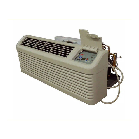
  9. Amana TE09095W2B Manual

Amana TE09095W2B Manual

Other Amana Air Conditioner manuals

Amana Thru-wall User manual

Amana

Amana Thru-wall User manual

Amana AAC051FRB User manual

Amana

Amana AAC051FRB User manual

Amana PBC123B00MB Quick start guide

Amana

Amana PBC123B00MB Quick start guide

Amana AAC081SRA Service Manual

Amana

Amana AAC081SRA Service Manual

Amana PTC073D00ARDA Owner's manual

Amana

Amana PTC073D00ARDA Owner's manual

Amana APUM3 M41AA Series Guide

Amana

Amana APUM3 M41AA Series Guide

Amana MBVC Series Service manual

Amana

Amana MBVC Series Service manual

Amana High Capacity Room Air Conditioner User manual

Amana

Amana High Capacity Room Air Conditioner User manual

Amana PBC092E00AX User manual

Amana

Amana PBC092E00AX User manual

Amana PTC MODELS Use and maintenance manual

Amana

Amana PTC MODELS Use and maintenance manual

Amana ASX14 User manual

Amana

Amana ASX14 User manual

Amana RCE Prestige User manual

Amana

Amana RCE Prestige User manual

Amana PTH models Installation instructions

Amana

Amana PTH models Installation instructions

Amana ACE156E User manual

Amana

Amana ACE156E User manual

Amana TDK02 User manual

Amana

Amana TDK02 User manual

Amana ACE24KE User manual

Amana

Amana ACE24KE User manual

Amana ACD10KE User manual

Amana

Amana ACD10KE User manual

Amana R-AMAP081BW User manual

Amana

Amana R-AMAP081BW User manual

Amana AMAP141AW User manual

Amana

Amana AMAP141AW User manual

Amana AP095R User manual

Amana

Amana AP095R User manual

Amana distinctions DCP073A25AA User manual

Amana

Amana distinctions DCP073A25AA User manual

Amana REFURBISHED R-AMAP084AW User manual

Amana

Amana REFURBISHED R-AMAP084AW User manual

Amana APN14J User manual

Amana

Amana APN14J User manual

Amana 10M52TB-P1230808R User manual

Amana

Amana 10M52TB-P1230808R User manual

Popular Air Conditioner manuals by other brands

Fujitsu ASYG 09 LLCA installation manual

Fujitsu

Fujitsu ASYG 09 LLCA installation manual

York HVHC 07-12DS Installation & owner's manual

York

York HVHC 07-12DS Installation & owner's manual

Carrier Fan Coil 42B Installation, operation and maintenance manual

Carrier

Carrier Fan Coil 42B Installation, operation and maintenance manual

intensity IDUFCI60KC-3 installation manual

intensity

intensity IDUFCI60KC-3 installation manual

Frigidaire FAC064K7A2 Factory parts catalog

Frigidaire

Frigidaire FAC064K7A2 Factory parts catalog

Sanyo KS2432 instruction manual

Sanyo

Sanyo KS2432 instruction manual

LG MultiV Series installation manual

LG

LG MultiV Series installation manual

CLIMAVENETA a-CHD U-2T 606+2209 OPERATING AND INSTALLATION Manual

CLIMAVENETA

CLIMAVENETA a-CHD U-2T 606+2209 OPERATING AND INSTALLATION Manual

Midea EWK06CW5 user manual

Midea

Midea EWK06CW5 user manual

Pioneer FAB Series installation manual

Pioneer

Pioneer FAB Series installation manual

SPT WA-1511S user manual

SPT

SPT WA-1511S user manual

Mitsubishi Electric Mr.Slim MSZ-A24NA operating instructions

Mitsubishi Electric

Mitsubishi Electric Mr.Slim MSZ-A24NA operating instructions

Mitsubishi Electric PUHZ-RP50VHA4 Service manual

Mitsubishi Electric

Mitsubishi Electric PUHZ-RP50VHA4 Service manual

Panasonic CS-S18HKQ Service manual

Panasonic

Panasonic CS-S18HKQ Service manual

Panasonic CS-E15NKE3 operating instructions

Panasonic

Panasonic CS-E15NKE3 operating instructions

Gree GWH18TC-K3DNA1B/I Service manual

Gree

Gree GWH18TC-K3DNA1B/I Service manual

Friedrich ZoneAire Compact P08SA owner's manual

Friedrich

Friedrich ZoneAire Compact P08SA owner's manual

Daikin R32 Split Series installation manual

Daikin

Daikin R32 Split Series installation manual

manuals.online logo
manuals.online logoBrands
  • About & Mission
  • Contact us
  • Privacy Policy
  • Terms and Conditions

Copyright 2025 Manuals.Online. All Rights Reserved.

Amana Technical Information—Room Air Conditioner
November 2001 RT4110048 Rev. 01
TE09095W2B TE09095W2B
• Due to a possibility of personal injury or property damage, always contact an authorized technician for servicing
or repair of this air conditioner.
• Refer to Service Manual RS4110008 for installation, operation, disassembly, testing, and troubleshooting
information.
• Refer to Parts Manual RAC-RP-133 for part number information.
CAUTION
!
All safety information must be followed as provided in Service Manual RS4110008.
!WARNING
To avoid risk of electrical shock that can cause death or severe injury, disconnect unit from power and discharge
capacitor through a 10,000-ohm resistor before servicing, unless tests require power. Wires removed during
disassembly must be replaced on correct terminals to ensure proper grounding and polarization.
Model TE09095W2B
Electrical requirements 230/208V VAC 60Hz
Refrigerant/amount HCFC22/30.885 ounces
Compressor
Voltage low/high (nominal)
BTUH
187/253 VAC (230/208 VAC)
9,200 BTUH
Watts 851/769.6 watts
Current
Lock rotor
Full load
22.2 amps
3.70 amps
Overload protector
Close temperature
Open temperature
Short time trip:
Time
Current
141.8°F ±48.2°F (61°C ±9°C)
275°F ±41°F (135°C ±5°C)
6.5-16 seconds
15 amps
Fan motor
Electrical requirements
RPM
Low speed
High speed
Watts at high speed
Current at high speed
230 VAC 60Hz
1050 RPM
1300 RPM
232 watts
1 amps
Capacitor
Capacitance
Voltage rating (nominal)
15/5 Mfd ±10%
370 VAC
Heater
Volts
Resistance
Watts
230 VAC
14.3 ohms ±3%
3400 watts
Component Specifications
November 2001 RT4110048 Rev. 02
!WARNING
To avoid risk of electrical shock that can cause death or severe injury, disconnect unit from power and
discharge capacitor through a 10,000-ohm resistor before servicing, unless tests require power. Wires
removed during disassembly must be replaced on correct terminals to ensure proper grounding and
polarization.
Illustration Component Test Procedure Results
BT9266117 Compressor Check resistance of compressor windings:
Attach ohmmeter between winding C and S:
Attach ohmmeter between winding C and R:
Check compressor for grounds:
Attach one ohmmeter lead to compressor
case. Attach second ohmmeter lead to C,
then S, then R terminals on compressor:
NOTE: See Testing Procedures section of Service Manual
for additional compressor information.
Ohmmeter should indicate resistance
between windings.
Ohmmeter should indicate resistance
between windings.
Ohmmeter should indicate infinity on each
terminal.
BT1243738
Compressor overload
Continuity
Ensure temperature of overload is at room temp.
Check continuity across leads:
Overload should have continuity.
BT9457013
Capacitor Resistance (highest scale), with power removed.
Discharge capacitor and disconnect all attached wires.
Attach Analog ohmmeter leads between C terminal
and H terminal on capacitor:
Reverse leads on C and H terminals:
Repeat for terminals C and F of capacitor:
Check capacitor for ground.
Attach one ohmmeter lead to capacitor
case. Attach second ohmmeter lead to H,
then C, then F terminals on capacitor:
Indicator swings to zero and slowly returns
toward infinity.
Indicator swings to zero and slowly returns
toward infinity.
If capacitor responds to results above
capacitor is OK.
Infinity on ohmmeter indicates capacitor not
grounded.
BT1340012
Fan motor Check for resistance of fan motor windings:
Attach one ohmmeter lead to common fan
motor lead. Attach second lead to remaining
fan motor leads, one at a time:
Check fan motor for grounds:
Attach one ohmmeter lead to fan motor case.
Attach second ohmmeter lead to each fan
motor lead, one at a time:
Ohmmeter should indicate resistance
between windings.
Ohmmeter should indicate infinity on each
lead.
BT1370832
Selector switch See wiring diagram for specific terminal positions.
Position Function
1Off
2Fan
3Low Cool
4High Cool
5High Heat
6Low Heat
Contacts Made
None
L1 and H; L2 and 1
L1 and M; L2 and 1; HC and C
L1 and H; L2 and 1; HC and C
L1 and H, L2 and 1; HC and HT
L1 and M, L2 and 1; HC and HT
BT1370807 Thermostat Attach ohmmeter leads between 2 and 1:
Attach ohmmeter leads between 2 and 3:
Turn control to warmest setting. Check for
continuity. Contacts close when control
warms.
Turn control to coldest setting. Check for
continuity. Contacts close when control
cools.
If continuity is not indicated, replace
affected control.
Component Specifications
November 2001 RT4110048 Rev. 03
!WARNING
To avoid risk of electrical shock that can cause death or severe injury, disconnect unit from power and
discharge capacitor through a 10,000-ohm resistor before servicing, unless tests require power. Wires
removed during disassembly must be replaced on correct terminals to ensure proper grounding and
polarization.
Illustration Component Test Procedure Results
BT1420008 Heater Assembly Check resistance with element at room temperature. Attach
ohmmeter between two leads on element. 14.4 ohms ±5%
BT1243735 Thermal Limit Check Continuity with limit at room temperature. Attach
ohmmeter to leads of limit.
Continuity
Open
Thermal Limit OK
Replace Thermal Limit
BT1243737
Thermal Cutout Check Continuity with cutout at room temperature. Attach
ohmmeter to leads of cutout.
Continuity
Open
Thermal Cutout OK
Replace Thermal Cutout
Wiring Diagrams and Schematics
November 2001 RT4110048 Rev. 04
!WARNING
To avoid risk of electrical shock that can cause death or severe injury, disconnect unit from power and
discharge capacitor through a 10,000-ohm resistor before servicing, unless tests require power. Wires
removed during disassembly must be replaced on correct terminals to ensure proper grounding and
polarization.
TE09095W2B TE09095W2B
©2001 Amana Appliances