Amana TDK02 User manual
Other Amana Air Conditioner manuals
Amana
Amana AAC051STA User manual

Amana
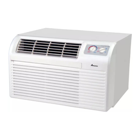
Amana ACW106R User manual
Amana
Amana PBE093B35MB Quick start guide
Amana
Amana ACD10JE User manual
Amana
Amana VCA Operating instructions
Amana
Amana APN14K User manual
Amana
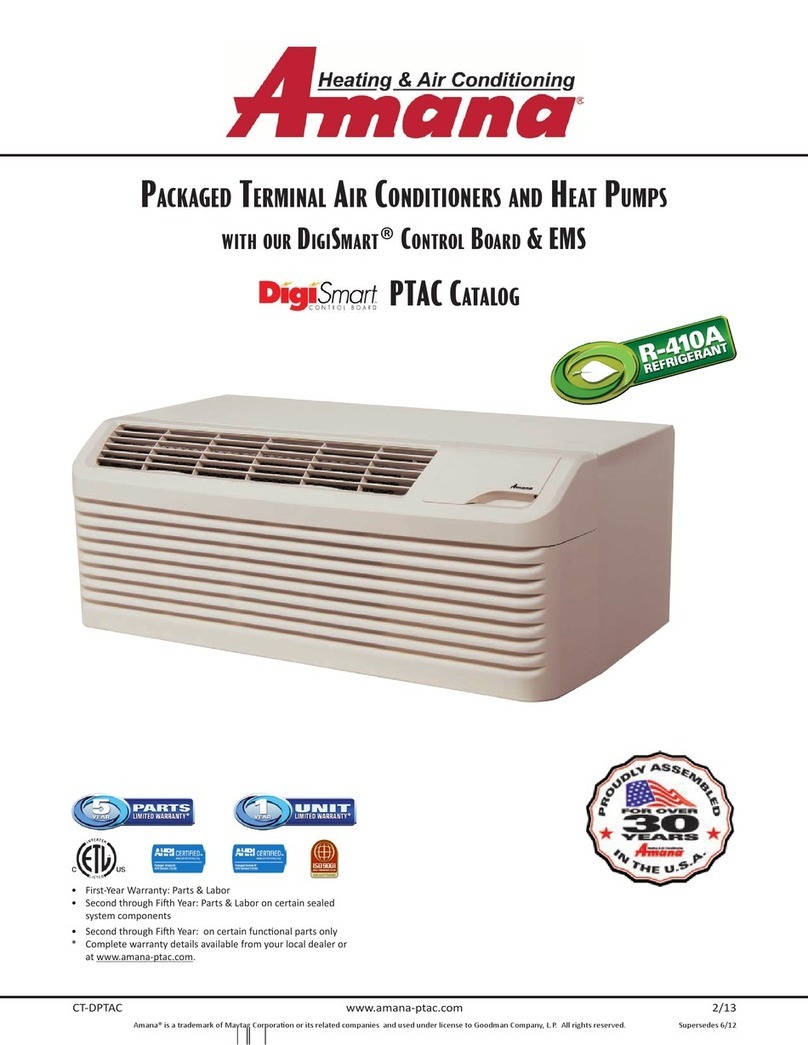
Amana CT-DPTAC Manual
Amana
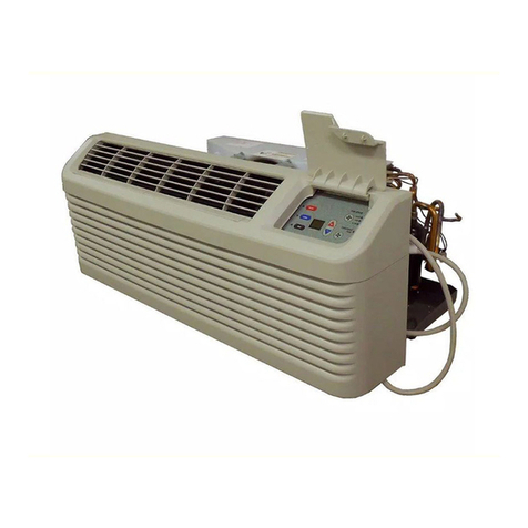
Amana PTAC 24" Service manual
Amana
Amana AAC051FRB User manual
Amana
Amana PBC123B00 Quick start guide

Amana
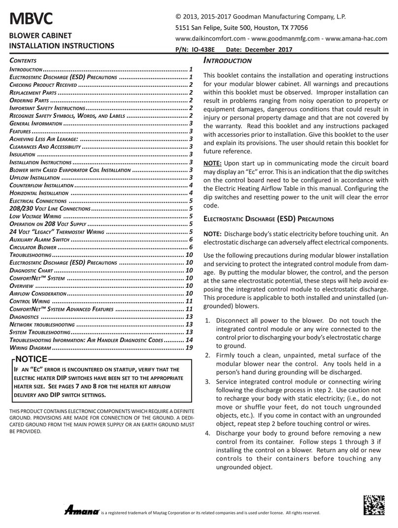
Amana RCA User manual
Amana
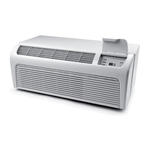
Amana MBVC Series Service manual
Amana
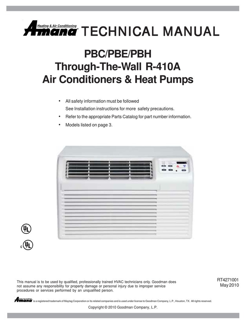
Amana PTH models Installation instructions
Amana
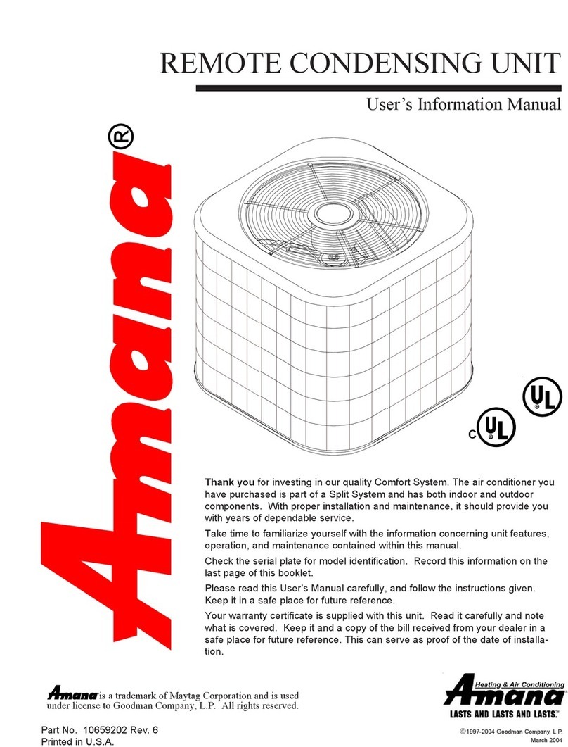
Amana R-410A User manual
Amana
Amana REMOTE CONDENSING UNIT Guide

Amana
Amana ASX 14 SEER User manual

Amana
Amana PTH123G25AXXX Service manual
Amana
Amana ACB06JE User manual

Amana
Amana Quiet Zone Room Air Conditioner User manual
Amana
Amana RSC Ultron User manual
Popular Air Conditioner manuals by other brands

CIAT
CIAT Magister 2 Series Installation, Operation, Commissioning, Maintenance

Bestron
Bestron AAC6000 instruction manual

Frigidaire
Frigidaire FFRE0533S1E0 Use & care guide

Samsung
Samsung AS09HM3N user manual

Frigidaire
Frigidaire CRA073PU11 use & care

Soleus Air
Soleus Air GB-PAC-08E4 operating instructions
