2
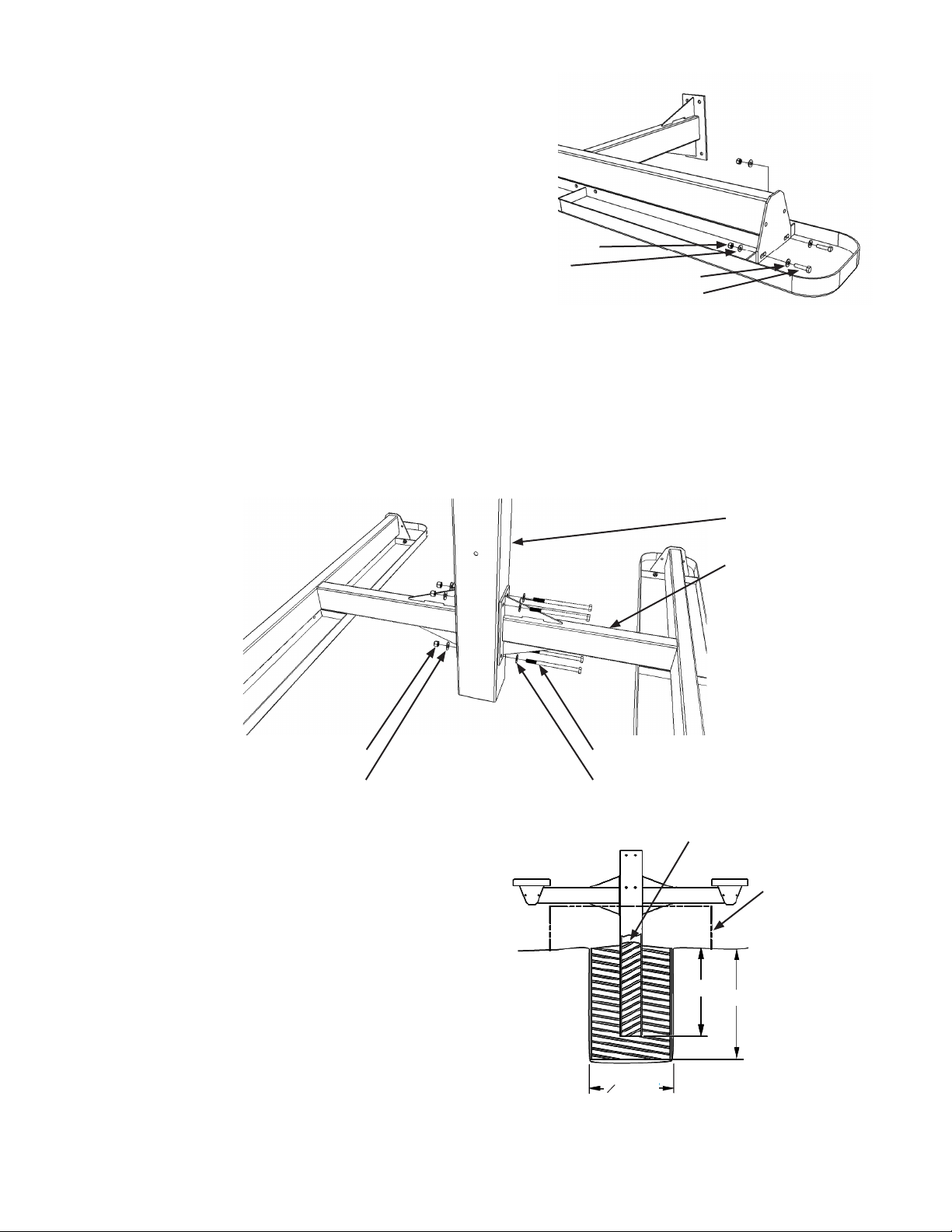
3. Locate one of the seats and seat supports. Align the mounting holes
in the seat support with the holes in the seat frame. Install one of the
5/16” at washers onto one of the 1 1/4” hex head bolts and insert the
bolt through both parts. Place a 5/16” at washer and 5/16” nylock nut
on the end of the bolt. Then tighten the hardware nger tight.
Repeat this for the remaining mounting holes on the opposite side of
the seat.
Repeat this step with the remaining seat and seat support.
4. Locate the in ground support and set it on the work surface with the end with the mounting holes down. Position the seat
support assemblies on either side of the in ground support. The seat support assemblies attach to the sides of the in ground
support with only 4 holes.
Place one of the 1/2” at washers onto one of the 7 1/2” hex head bolts. Align the mounting holes in the seat supports with the
mounting holes in the in ground support and install the bolt through the set of mounting holes all three parts.
Place a 1/2" at washer and a 1/2" nylock nut on the end of the 7 1/2" hex head bolt. Then tighten the hardware nger tight.
Repeat this for each of the remaining 7 1/2” hex head bolts and mounting holes. Aer all four bolts are installed, use the
3/4”-ratchet and 3/4”- open or box-end wrench to tighten the hardware.
5. Determine the location for the table
6. The walls of the concrete base should be vertical and smooth
to minimize the eects of frost upheaval. This can be achieved
with the use of concrete forms, such as Sonotube®. Consider
extending the concrete base below the frost line. Consult a
professional for loose or unusual soil conditions.
8.
Create a temporary structure that will be used to support the in
ground support assembly, at the desired height and level, while
the concrete is curing.
5/16" - 18 x 1 1/4”
Hex Head Bolt
5/16" Flat Washer
5/16" Flat Washer
5/16" - 18 Nylock Nut
1/2" - 13 x 7 1/2" Hex Head Bolt
1/2" Flat Washer1/2" Flat Washer
1/2" - 13 Nylock Nut
24.00"
O 24.00"
30.00" MIN
Drain Hole
Temporary structure
to hold the assembly
vertical, level, and at
the correct height
IMPORTANT: Locate underground utilities and avoid them
while digging the hole for the concrete base.
Fill the form with concrete and insert the in ground support
assembly, centered in the concrete, until the seat supports are
supported by the temporary structure. Allow the interior of
the in ground support to ll with concrete up to the drain hole.
Crown the concrete cap to optimize drainage. Allow the concrete
to cure before attaching the table top supports.
Aer the concrete has cured, the installation hole is backlled, and the temporary structure is removed, use the ratchet with
1/2” socket and the 1/2” open or box end wrench to tighten the seat hardware. Check with a level and adjust the seats as
needed while tightening.
9.
7.
In Ground Support
Seat Support


