AnyTone AT-500M User manual

Qixiang Electon Science & Technoloyg Co.,Ltd.
www.anytone.net
A1.190716

10 METER RADIO
AT-500M
Instruction Manual

1AT-500M
Down UP
Microphone cable
Mic
PTT
Connector
1. KNOW ABOUT THIS RADIO
1 Mode/Keypad lock
2 Squelch control, SQ, ASQ switch key
3 Microphone Jack
4 Channel up selector
5 Channel down selector
6 Emergency channel
7 Power On/Off Volume control
8 External speaker Jack
9 Antenna Jack
ANT
POWER
EXT.SP
8
9
EMG
MENU
VOL
CH
SQ/AQ
AM/FM
1
26
7
3
4
5
HI-CUT
RF Gain
Automatical Squelch
Noise Blanker
TALKBACK
Roger Beep
TX
PA/AM/FM mode
TX/RX S-meter
Channel/Frequency
Offset Direction
Offset Direction
CTCSS DCS VOX
-5K
Alpha channel
High power
Middle power
Key lock
Beep sound
Emergency channel
BAND name
Channel
/Menu
Function and Features
7 COLOR DISPLAY
1.
OFFSET FUNCTION
2.
3.
4.
AM/FM/PA MODE
5.
6.
7.
8.
9.
SQ, ASQ FUNCTION
10.
RF GAIN FUNCTION
11.
12.
SCAN FUNCTION
13.
RB FUNCTION
14.
NB FUNCTION
15.
DUAL-WATCH FUNCTION
16.
BEEP SOUND
17.
18.
TOT FUNCTION
HI-CUT FUNCTION
EMG CALL
CTCSS/DCS CODE ( OPTIONAL)
KEY LOCK FUNCTION
BUILT IN 12/24V CONVERTOR (OPTIONAL)
VOX FUNCTIONS( TRANSMIT WITHOUT PRESS PTT)
19.
20.
SUIT DYMATIC AND ELECTRONIC MICROPHONE
BACKLIGHT BRIGHTLESS ADJUSTABLE
-5KHZ FUNCTION

AT-500M 2
2. LCD
HI-CUT
RF Gain
Automatical Squelch
Noise Blanker
TALKBACK
Roger Beep
TX
PA/AM/FM mode
TX/RX S-meter
Channel/Frequency
Offset Direction
Offset Direction
CTCSS DCS VOX
-5K
Alpha channel
High power
Middle power
Key lock
Beep sound
Emergency channel
BAND name
Channel
/Menu
Function and Features
7 COLOR DISPLAY
1.
OFFSET FUNCTION
2.
3.
4.
AM/FM/PA MODE
5.
6.
7.
8.
9.
SQ, ASQ FUNCTION
10.
RF GAIN FUNCTION
11.
12.
SCAN FUNCTION
13.
RB FUNCTION
14.
NB FUNCTION
15.
DUAL-WATCH FUNCTION
16.
BEEP SOUND
17.
18.
TOT FUNCTION
HI-CUT FUNCTION
EMG CALL
CTCSS/DCS CODE ( OPTIONAL)
KEY LOCK FUNCTION
BUILT IN 12/24V CONVERTOR (OPTIONAL)
VOX FUNCTIONS( TRANSMIT WITHOUT PRESS PTT)
19.
20.
SUIT DYMATIC AND ELECTRONIC MICROPHONE
BACKLIGHT BRIGHTLESS ADJUSTABLE
-5KHZ FUNCTION

3
3. HOW TO USE THIS RADIO
3.1 Power On/Off the Radio.................................................................
3.3 Channel Control ..............................................................................
3.2 Volume Control ...............................................................................
※Squelch level Control (short press)
※ASQ Control (long press)
(1) Turn VOL switch clockwise to power on the radio, the LCD displays the
Norms and then displays channel number.
(2) Turn VOL switch anti-clockwise, until hear Ka Ta, the radio is powered
off.
(1) Short press [UP]/[DN] key to change channel by one step.
(2) Hold [UP]/[DN] can fast changed channel.
Note: The standard version support 12V DC power supply. optional version
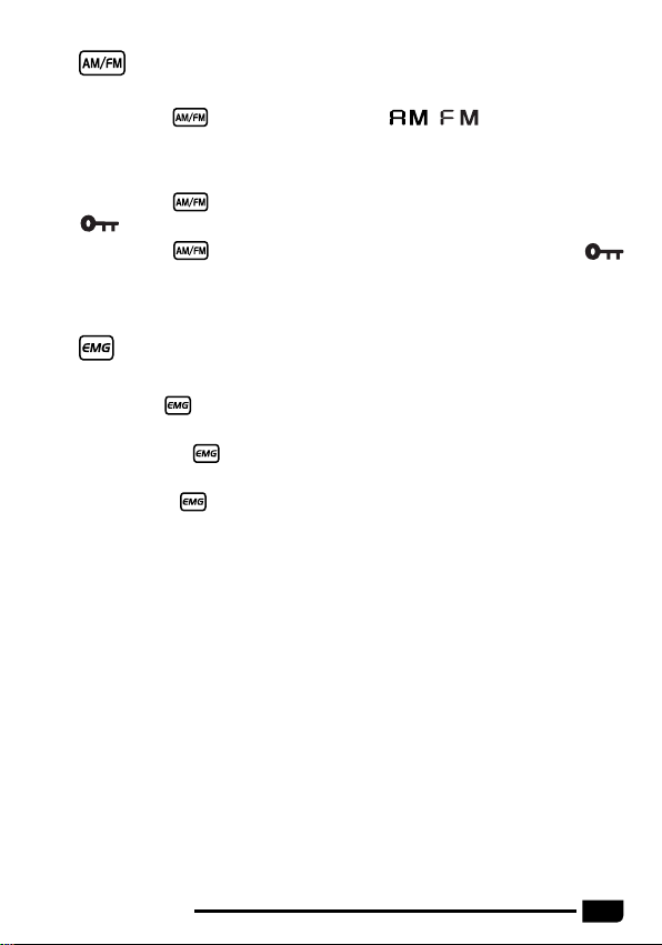
(1) Short press
SQ/AQ
, until LCD displays " ", " " stands for
SQ/AQ level, the bigger value stands for high squelch level.
(2) Short press microphone [ UP ] or [ DN ] to change SQ/AQ level.
(3) Long press microphone [ UP ] or [ DN ] can fast change SQ/AQ level.
(4) Short press
SQ/AQ
or wait for 10 seconds to store and exit.
Note: The higher SQ level selected, the stronger signal required to open
speaker and hear the calling.
(1) Long press , until LCD displays "AQ", the ASQ function turned on.
(2) Short press , until LCD displays " ", " " stands for ASQ
level, the bigger value stands for high squelch level.
(3) Short press [UP]/[DN] to change ASQ level.
(4) Hold [UP]/[DN] can fast change ASQ level.
(5) Short press or wait for 10 seconds to store and exit.
(6) Long press key again to turn on SQL function.
Note: The higher ASQ level selected, the stronger signal required to open
speaker and hear the calling.
Turn clockwise to increase volume, anti-clockwise to decrease volume.
3.4
SQ/AQ
...................................................................................................
support 12+24V check your version before connect power supply.
AT-500M

4
※Mode Control (short press)
※Emergency Channel (short press)
※Functions (long press)
※Keypad Lock (long press)
(1) Short press , key to switch between / mode.
(2) The LCD displays the selected mode.
(1) First press , key to choose the first programmed emergency channel,
LCD displays EMG1.
(2) Second press , key to choose the second programmed emergency
channel.
(3) Third press , key to return to last normal channel, LCD displays
EMG2.
Note: The default emergency channel are channel 9 and channel 19.
See menus Emergency Channel Set page 8 for the emergency channel
configuration.
(1) Hold [UP ]/[DN] for over 5 seconds, when you hear /di di/, scan started.
(2) Short press [UP ]/[DN] key to change scan direction.
(3) Short press [AM]/[FM] to change mode, short press EMG or [PTT] to exit
scan.
Long press key to enter in memu and set different function.
(1) Long press key for over 2 seconds to lock the keys, LCD displays
.
(2) Long press key for over 2 seconds again to unlock the keys
disappears form LCD.
Note: In lock Mode all keys except PTT is valid.
3.5 ..................................................................................................
3.6 .....................................................................................................
3.7 Scan Function...................................................................................
AT-500M

5
The VOX function allows transmitting by speaking into the original
microphone without pressing the PTT switch.
Press [PTT] + [EMG] key to activate VOX function, LCD displays
microphone icon, and then press [PTT] + [EMG] key to disable VOX
function. The microphone icon disappeared.
Note: When turn on VOX, the mic icon flashes, VOX sensitivity and time
setting refer to page 6.
This function allows you to select the mode of operation for public
broadcasting.
Turn on PA mode: "PA" and modulation mode (AM/FM) flicker alternately.
The volume switch knob is used to adjust the audio level of mode PA.
This function allows you to adjust the volume of your walkie-talkie.
(1) Start the intercom function (see "intercom" on page 8).
(2) Hold down the PTT switch, then the [up] key increases or the [down] key
decreases the Talkback Level
(3) Release PTT switch and save Talkback Level.
Choose a 8Ω external speaker with 3.5 mm mono connector.
(1) Long press key to enter menu list.
(2) Short press microphone [ UP ] or [ DN ] or or to choose menu
to be.
(3) Short press key to enter function setting parameter of the chosen
function, the parameter blinks on LCD.
(4) Short press microphone [ UP ] or [ DN ] or or to choose
wanted setting.
(1) Hold to power on radio, until LCD displays the norms.
(2) Short press or or microphone [UP ]/[DN].
(3) Power off and power on again.
3.12 Install External Speaker ..............................................................
3.13 Menu Operations ..........................................................................
3.8 VOX function.....................................................................................
3.9 PA Function.......................................................................................
3.10 Talkback Level ...............................................................................
3.11 Norms Control ................................................................................
AT-500M

6
(5) Short press key to validate the mode and exit setting.
(6) Long press key or wait 10 seconds to store exit MENU.
NO. LCD display Function detail Setting details
1CTCSS/DCS
encode/decode
: CTCSS/DCS is OFF;
CT: 67.0Hz~250.3Hz;
DT: D023N~D754N;
Note: This function is optional.
2Beep sound
: turn on beep sound
: turn off beep sound
Default:
3 RF power setting
LO: low power
nI: middle power
HI: high power
Default: LO
Note: This function is valid only when the
radio work in HF model or HAM model.
4 Scan type setting
Sq: squelch scan
tI: time scan
Default:
5 HI-CUT setting
: turn off HI-CUT function
: turn on HI-CUT function
Default:
6Microphone gain 1~9, Total 9 levels
Default: 6
7Microphone type
EL: Electronic
dy: Dynamic
Default: EL
8VOX Sensitivity 1~9: total 9 levels
Default: 3
9 VOX Time 1~9: Total 9 levels
Default: 4
10 Talkback level
control
, 1~9
Default:
Note: Speak into microphone and watch
the S-meter to choose wanted mic gain .
AT-500M

7
NO. LCD display Function detail Setting details
11 Noise blanker
: turn off ANL/NB function
: turn on ANL/NB function
Default:
12 Offset direction
: Turn off offset;
-: negative offset, TX frequency low than RX
frequency;
+: minus offset, TX frequency high than RX
frequency;
13 RF gain level
control
Level AU 03,06,09~48
Default: oF
Note: If the AUTO RFG function is on,
the radio will turn on the automatic
RFG function.
14 RB sound setting
, 1-5
: turn off RB sound function.
Default:
15 Backlight color
setting
OR: Orange
gr: Green
bL: Blue
Cy: Cyan
yE: Yellow
PU: Purple
CL: White
Default: OR
16 Backlight
brighless
Level 1~6
Default: 4
17 Time out timer , 1~10Min
Default: 1
18 Frequency
-5KHz function
:turn on -5KHz function
:turn off -5KHz function
Default:
Note: This function is only valid for
radio operating in HAM mode.
Note: Valid only in HF or HAM mode.
AT-500M

8
(1) Choose a band to be modified.
(2) Long press key to enter menu list.
(3) Short press microphone [ UP ] or [ DN ] or or to choose BAND
name function memu, LCD displays .
(4) Short press key, the first digit blinks on LCD.
(5) Short press microphone [ UP ] or [ DN ] or or to choose the
character of the first digit.
(6) Short press key to validate the first digit. The second digit blinks on
LCD.
(7) Short press microphone [ UP ] or [ DN ] or or to choose the
character of the second digit.
(8) Short press key to validate the second digit and exit setting.
(9) Long press key or wait 10 seconds to store exit MENU.
(1) Long press key to enter menu list.
(2) Short press microphone [ UP ] or [ DN ] or or to choose EMG
function memu, LCD displays EMG1--09 on or EMG2--19 on.
(3) Short press EMG key, the character "on" or character "oF" blinks on
LCD.
(4) Short press microphone [ UP ] or [ DN ] or or to choose the
emergency channel is valid.
: stands for turn off current emergency channel.
(5) Short press key, the band name blinks on LCD.
(6) Short press microphone [ UP ] or [ DN ] or or to choose the
frequency band.
Note: This frequency band selection is valid only when the radio work in HF
model or HAM model.
3.14 Band Name Setting ......................................................................
3.15 Emergency Channel Setting .......................................................
AT-500M

9
(1) Long press key to enter menu list.
(2) Short press microphone [ UP ] or [ DN ] or or to choose reset
function memu, LCD displays .
(3) Short press key to enter menu selection, falshes in the
LCD.
(4) Long press key key until LCD only displays .
(5) Release key, the radio automatically reseted.
3.16 Resume Factory Default ............................................................
(7) Short press key to validate the frequency band,and the channel
blinks on LCD.
(8) Short press microphone [ UP ] or [ DN ] or or to choose the
channel.
(9) Short press key to validate the channel,and the mode blinks on LCD.
(10) Short press microphone [ UP ] or [ DN ] or or to choose the
mdoe AM or FM.
(11) Short press key to validate the mode and exit setting.
(12) Long press key or wait 10 seconds to store exit MENU.
Note: Choose the frequency band is valid only when the radio work in HF
model or HAM model.
AT-500M

10
4. SPECIFICATION
GENERAL
Modulation Mode AM/FM
Frequency Range 28-29.7MHz
Frequency Tolerance ±5.0ppm
Input Voltage 13.8V
Dimensions 185x124x38mm
Weight 620g
Operating Temperature Range -20℃ to +50℃
Current Drain
Transmit 5A MAX
Receive Squelched 0.3A
VOL Max 0.7A
Antenna Connector UHF, SO-239
TRANSMITTER
Power Output AM 7W, FM15W
Transmission interference inferior to 4nW
Frequency Response 300-3000Hz
Modulated signal distortion inferior to 5%
Output Impedance 50 ohms
RECEIVER
Sensitivity Less than 1uV for 10dB(S+N)/N
Image Rejection 70dB
Adjacent Channel Rejection 60dB
IF Frequencies 1st 10.695MHz
2nd 455KHz
Automatic Gain Control(AGC) Less than 10dB change in audio
Output for inputs from 10 to 50000uV
Squelch less than 1uV
Audio Output Power 2Watts at 8Ω less than 10% distortion
Frequency Response 300-3000Hz
AT-500M

11 AT-500M
This device complies with Part 15 of the FCC Rules. Operation is subject
to the following two conditions: (1) this device does not cause any harmful
interference; and (2) this radio must accept any interference that may
cause undesired operations.
Note: This equipment has been tested and found to comply with the limits for a
Class B digital device, pursuant to part 15 of the FCC Rules. These limits are
designed to provide reasonable protection against harmful interference in a
residential installation. This equipment generates, uses and can radiate radio
frequency energy and, if not installed and used in accordance with the instructions,
may cause harmful interference to radio communications. However, there is no
guarantee that interference will not occur in a particular installation. If this equipment
does cause harmful interference to radio or television reception, which can be
determined by turning the equipment off and on, the user is encouraged to try to
correct the interference by one or more of the following measures:
—Reorient or relocate the receiving antenna.
—Increase the separation between the equipment and receiver.
—Connect the equipment into an outlet on a circuit different from that to which
the receiver is connected.
—Consult the dealer or an experienced radio/TV technician for help.
Licensing Information
Use our radio in USA is subject to the rules & regulations of FCC. Changes or
modifications not expressly approved by our may void the user authority granted by
the FCC to operate this radio and should not be made. To comply with FCC
requirements, transmitter adjustments should be made only by or under the
supervision of a person certified as technically qualified to perform transmitter
maintenance and repairs in the private land mobile and fixed services as certified by
an organization representative of the user of those services. Replacement of any
transmitter component (crystal, semiconductor, etc) not authorized by the FCC
equipment authorization for this radio could violate FCC rules.
Note: Use of this radio outside the country where it was intended to be distributed is
subject to government regulations and may be prohibited.
Important: Any changes or modifications not expressly approved by the party
responsible for compliance could void the user's authority to operate this device. Your
radio is set up to transmit a regulated signal on an assigned frequency. It is against
the law to alter or adjust the settings inside the radio to exceed those limitations. Any
adjustments to your radio must be made by qualified technicians.
WARNING: MODIFICATION OF THIS DEVICE TO RECEIVE CELLULAR RADIOTELEPHONE
SERVICE SIGNALS IS PROHIBITED UNDER FCC RULES AND FEDERAL LAW.
WARNING
Table of contents
Other AnyTone Radio manuals

AnyTone
AnyTone AT 778 User manual

AnyTone
AnyTone AT888 User manual

AnyTone
AnyTone AT-300M User manual

AnyTone
AnyTone AT-588UV User manual

AnyTone
AnyTone 868 User manual

AnyTone
AnyTone SMART User manual

AnyTone
AnyTone Ares User manual

AnyTone
AnyTone SMART II User manual

AnyTone
AnyTone AT-588 User manual

AnyTone
AnyTone DORIS User manual

AnyTone
AnyTone AT-D578UV User manual

AnyTone
AnyTone GRACES User manual

AnyTone
AnyTone AT- 778UV User manual

AnyTone
AnyTone DMR AT-D878U User manual

AnyTone
AnyTone AT-598 User manual

AnyTone
AnyTone AT-5189 User manual

AnyTone
AnyTone APOLLO I User manual

AnyTone
AnyTone ARES II User manual

AnyTone
AnyTone AT-318UV User manual

AnyTone
AnyTone Dual Band FM Transceiver User manual