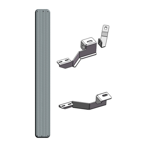
APS iBoard IB-014A-B User manual
Other APS Automobile Accessories manuals
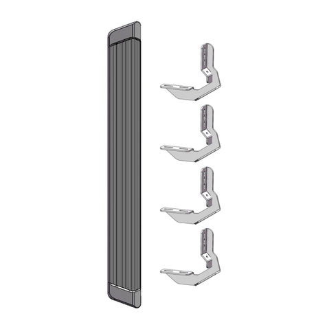
APS
APS iBoard IB-R004 User manual
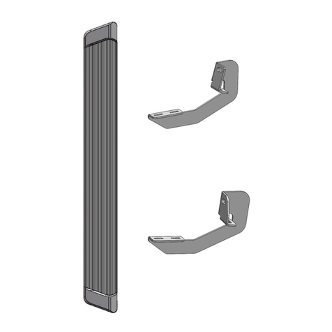
APS
APS iBoard IB-R009 User manual

APS
APS IA06SJD4B User manual
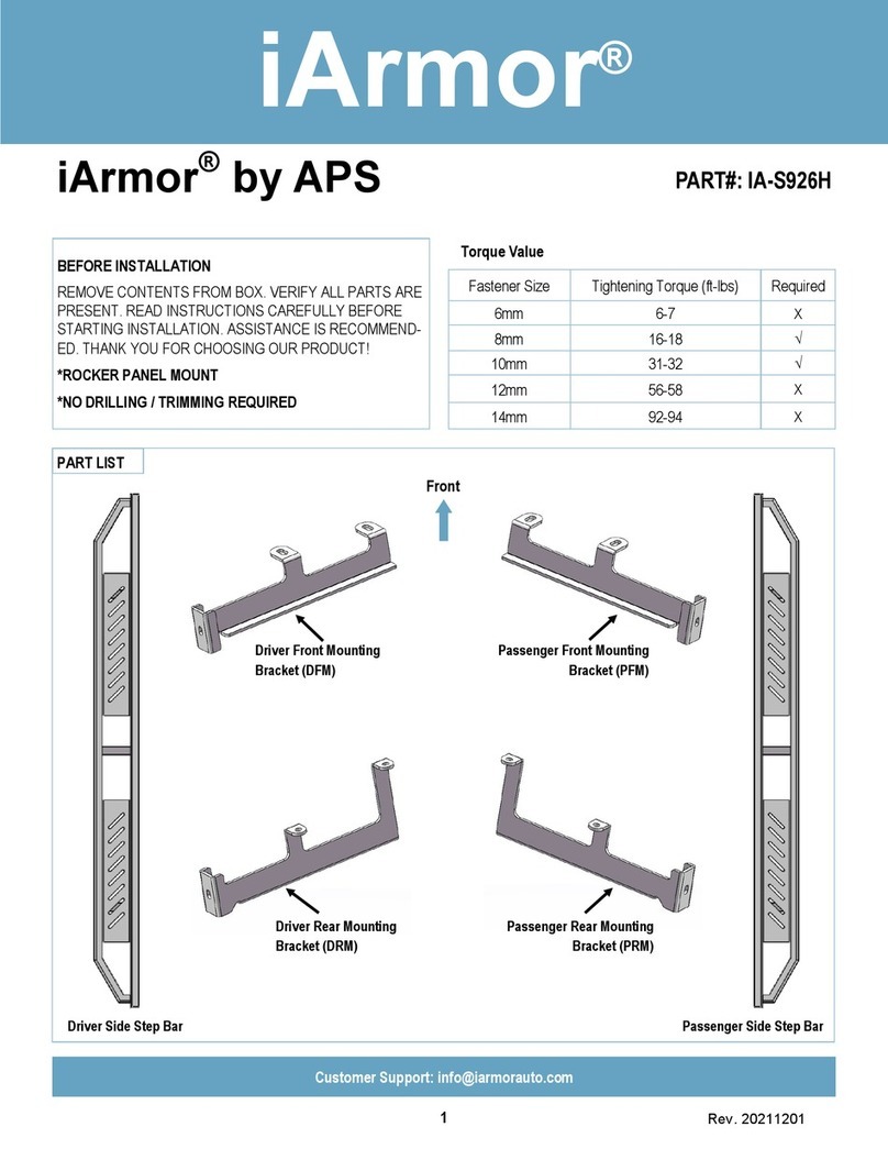
APS
APS iArmor IA-S926H User manual
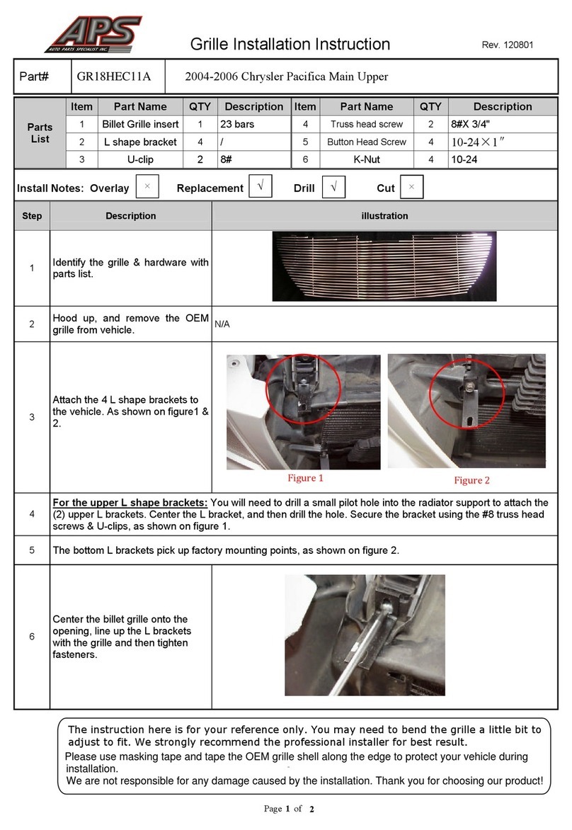
APS
APS GR18HEC11A User manual
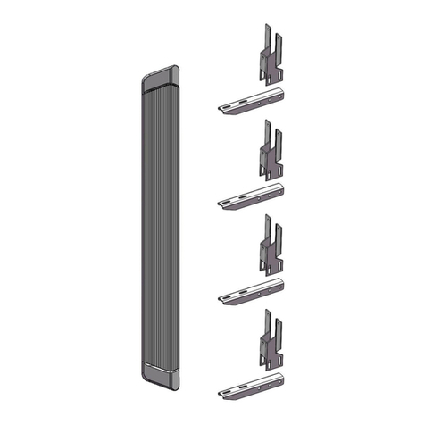
APS
APS iBoard IB-R911 User manual
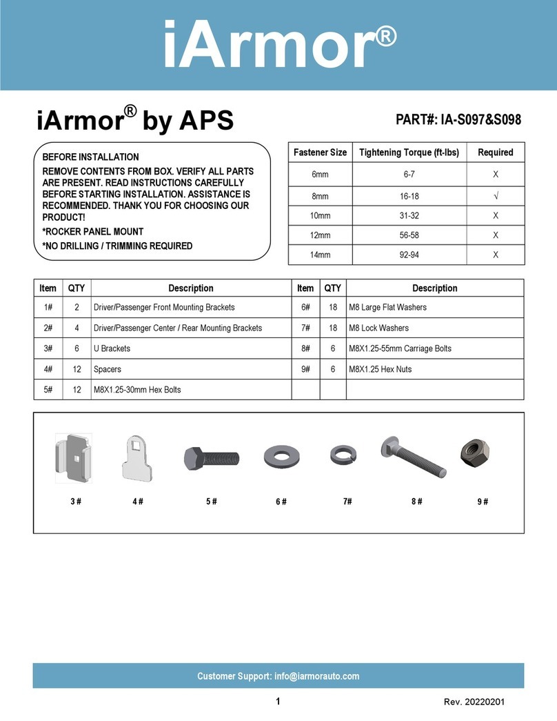
APS
APS iArmor User manual
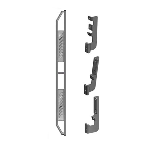
APS
APS iArmor IA-S002H User manual
APS
APS ELM205-V10 User manual
APS
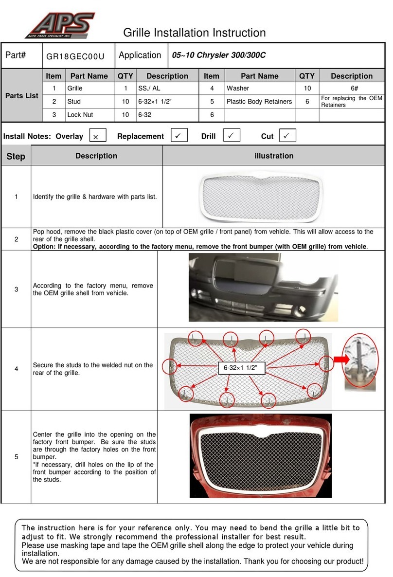
APS GR18GEC00U User manual
APS
APS iBoard IB-R934 User manual

APS
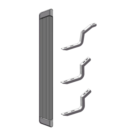
APS iBoard IB-R961 User manual
APS
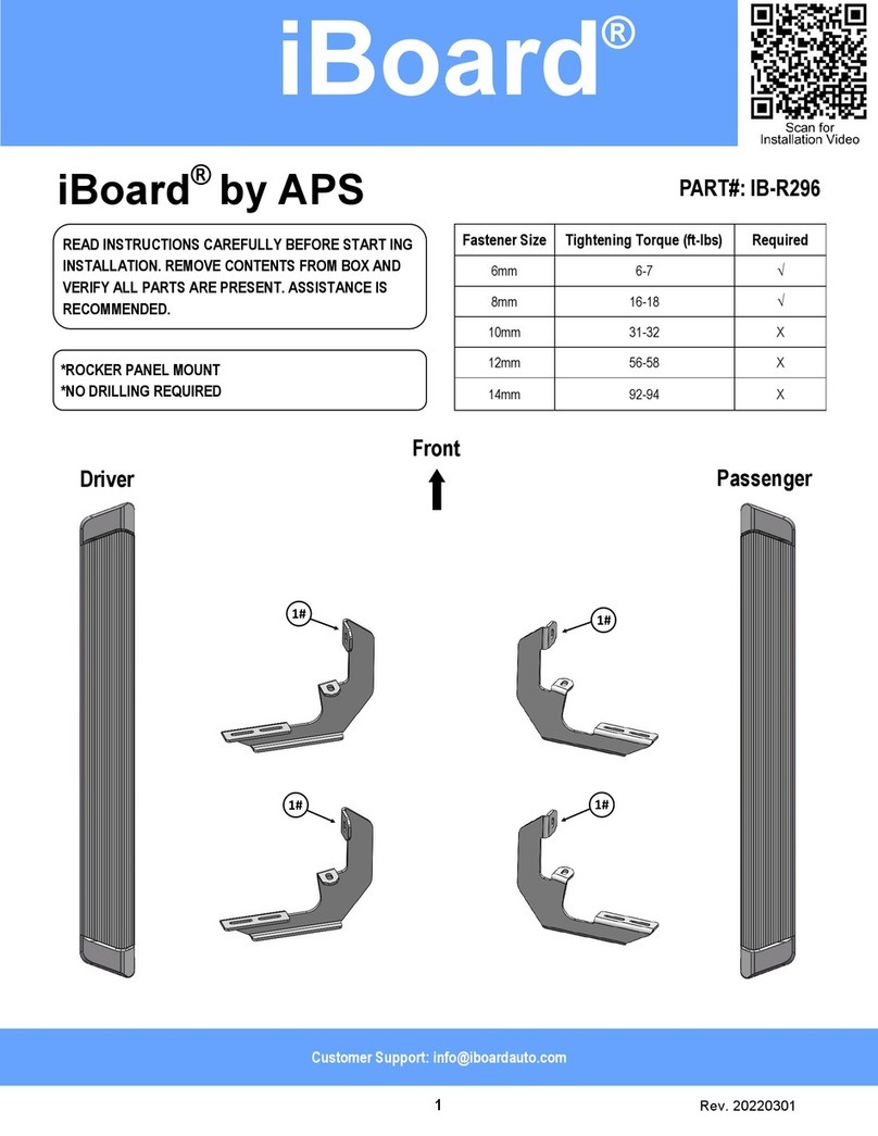
APS iBoard IB-R296 User manual
APS
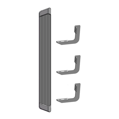
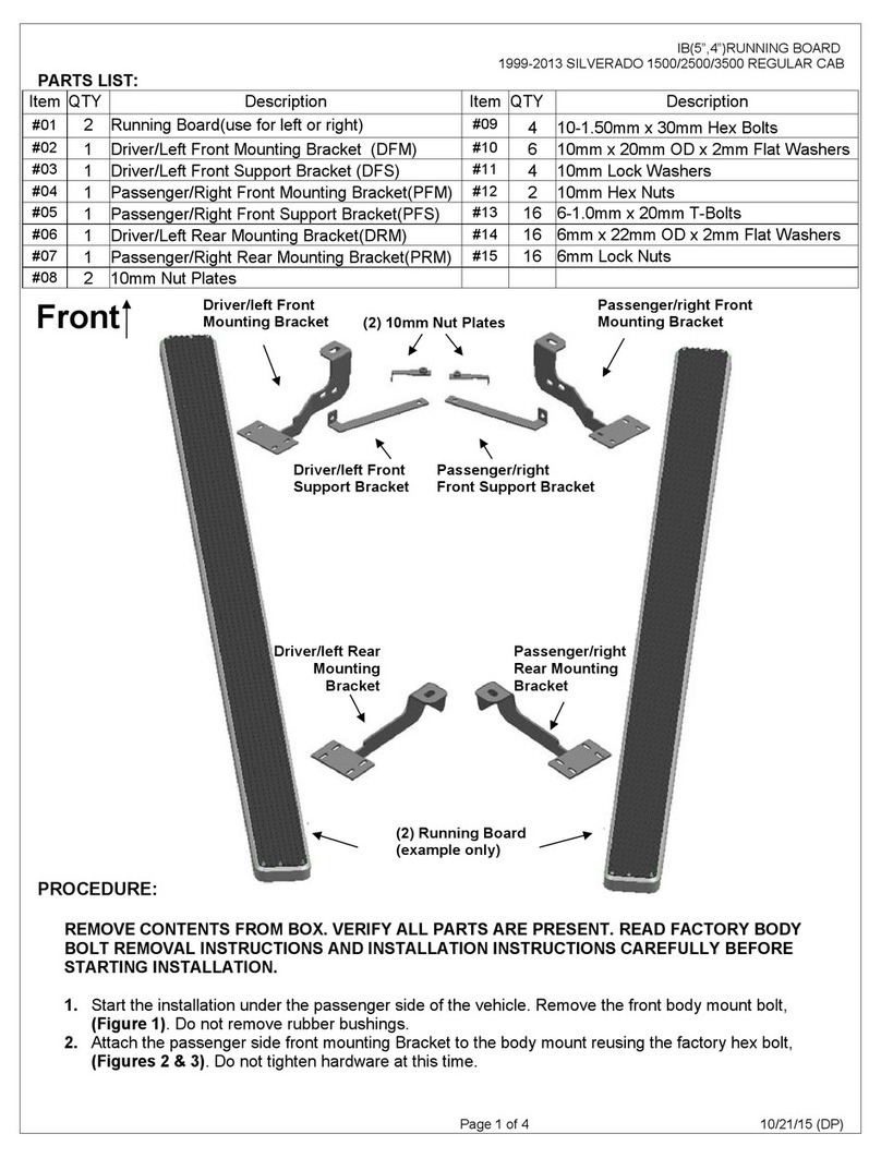
APS iBoard IB-R094 User manual
APS
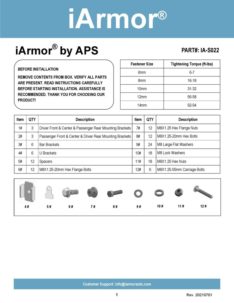
APS IB03DJJ7A User manual
APS
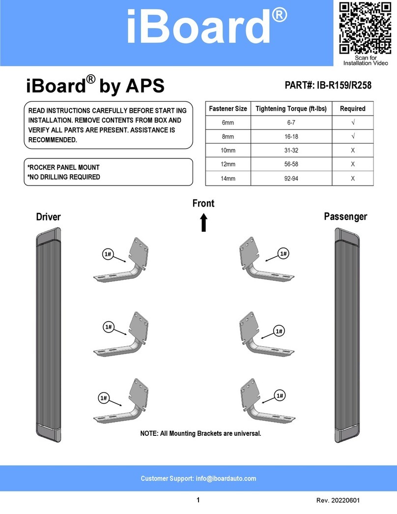
APS iArmor IA-S022 User manual
APS
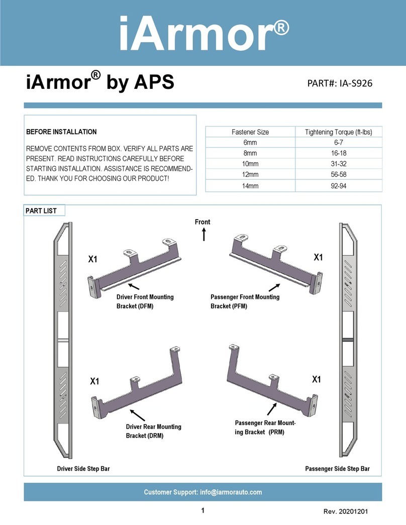
APS iBoard IB-R159 User manual
APS
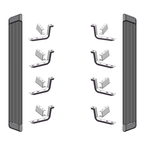
APS iArmor IA-S926 User manual
APS
APS iBoard IB-R922 User manual
APS
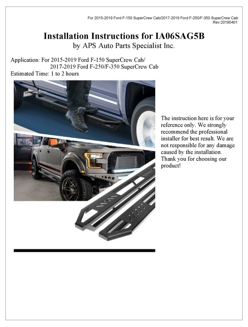
APS IA06SAG5B User manual
Popular Automobile Accessories manuals by other brands

ULTIMATE SPEED
ULTIMATE SPEED 279746 Assembly and Safety Advice

SSV Works
SSV Works DF-F65 manual

ULTIMATE SPEED
ULTIMATE SPEED CARBON Assembly and Safety Advice

Witter
Witter F174 Fitting instructions

WeatherTech
WeatherTech No-Drill installation instructions

TAUBENREUTHER
TAUBENREUTHER 1-336050 Installation instruction
