manuals.online logo
Brands
  1. Home
  2. •
  3. Brands
  4. •
  5. Argos
  6. •
  7. Indoor Furnishing
  8. •
  9. Argos Cheval 147/8985 User manual

Argos Cheval 147/8985 User manual

This manual suits for next models

3

Other Argos Indoor Furnishing manuals

Argos 501-3298 User manual

Argos

Argos 501-3298 User manual

Argos Franklin Recliner 2493567 User manual

Argos

Argos Franklin Recliner 2493567 User manual

Argos CANVAS 214/6601 User manual

Argos

Argos CANVAS 214/6601 User manual

Argos 832/8076 User manual

Argos

Argos 832/8076 User manual

Argos Jenson 937/8032 User manual

Argos

Argos Jenson 937/8032 User manual

Argos Dalton 617/3601 User manual

Argos

Argos Dalton 617/3601 User manual

Argos OI WOW Eclipse 147/9726 User manual

Argos

Argos OI WOW Eclipse 147/9726 User manual

Argos Matrix 609/0739 User manual

Argos

Argos Matrix 609/0739 User manual

Argos HOME 466/3175 User manual

Argos

Argos HOME 466/3175 User manual

Argos 149113 User manual

Argos

Argos 149113 User manual

Argos Malibu 621/3310 User manual

Argos

Argos Malibu 621/3310 User manual

Argos Swanley 120 307/0013 User manual

Argos

Argos Swanley 120 307/0013 User manual

Argos 737/8876 User manual

Argos

Argos 737/8876 User manual

Argos Oslo Oak Table 603/3071 User manual

Argos

Argos Oslo Oak Table 603/3071 User manual

Argos Verona Beech User manual

Argos

Argos Verona Beech User manual

Argos Vince 697/1470 User manual

Argos

Argos Vince 697/1470 User manual

Argos Capella 615/6831 User manual

Argos

Argos Capella 615/6831 User manual

Argos salisbury 338/4400 User manual

Argos

Argos salisbury 338/4400 User manual

Argos Arizona 461/6366 User manual

Argos

Argos Arizona 461/6366 User manual

Argos Dalton 246/6422 User manual

Argos

Argos Dalton 246/6422 User manual

Argos 1866968 User manual

Argos

Argos 1866968 User manual

Argos Islington Installation guide

Argos

Argos Islington Installation guide

Argos 831/9418 User manual

Argos

Argos 831/9418 User manual

Argos 346/0348 User manual

Argos

Argos 346/0348 User manual

Popular Indoor Furnishing manuals by other brands

Regency LWMS3015 Assembly instructions

Regency

Regency LWMS3015 Assembly instructions

Furniture of America CM7751C Assembly instructions

Furniture of America

Furniture of America CM7751C Assembly instructions

Safavieh Furniture Estella CNS5731 manual

Safavieh Furniture

Safavieh Furniture Estella CNS5731 manual

PLACES OF STYLE Ovalfuss Assembly instruction

PLACES OF STYLE

PLACES OF STYLE Ovalfuss Assembly instruction

Trasman 1138 Bo1 Assembly manual

Trasman

Trasman 1138 Bo1 Assembly manual

Costway JV10856 manual

Costway

Costway JV10856 manual

moss DESIGN Caisson Credenza Assembly instructions

moss DESIGN

moss DESIGN Caisson Credenza Assembly instructions

Aquaglide FULL DECK 15.0 owner's manual

Aquaglide

Aquaglide FULL DECK 15.0 owner's manual

AREBOS AR-HE-SW30 user manual

AREBOS

AREBOS AR-HE-SW30 user manual

Till-Hilft Fulda 87005.330 Assembly instructions

Till-Hilft

Till-Hilft Fulda 87005.330 Assembly instructions

Twoey Outside 2010 quick start guide

Twoey Outside

Twoey Outside 2010 quick start guide

Hettich Easys 200 operating instructions

Hettich

Hettich Easys 200 operating instructions

The bedboss RELAX 404 Series owner's manual

The bedboss

The bedboss RELAX 404 Series owner's manual

Oeseder Möbelindustrie Bern 991 720 Assembly instructions

Oeseder Möbelindustrie

Oeseder Möbelindustrie Bern 991 720 Assembly instructions

Costway HW68469 user manual

Costway

Costway HW68469 user manual

Next ALIX A27743 Assembly instructions

Next

Next ALIX A27743 Assembly instructions

BROSA Hans Assembly guide

BROSA

BROSA Hans Assembly guide

Prodigg MINIKA PBA015T-FUR installation manual

Prodigg

Prodigg MINIKA PBA015T-FUR installation manual

manuals.online logo
manuals.online logoBrands
  • About & Mission
  • Contact us
  • Privacy Policy
  • Terms and Conditions

Copyright 2025 Manuals.Online. All Rights Reserved.

MADE IN
BRITAIN
Dimensions
Width - 69cm
Depth - 49.5cm
Height - 200cm
Cheval - 2 Door Mirror Robe
Assembly Instructions - Please keep for future reference
If you need help or have damaged or missing parts, call the Customer Helpline: 08456 400800
Issue 1 - 31/01/14
Important - Please read these instructions fully before starting assembly
ALR2965
147/8985
151/7626
147/4549
151/3091
Safety and Care Advice
Important - Please read these instructions fully before starting assembly
• Warning: This unit weighs
approximately 52kgs.
Please lift with care.
• Check you have all the
components and tools listed on
pages 2 and 3.
• Remove all fittings from the
plastic bags and separate them
into their groups.
• Keep children and animals
away from the work area, small
parts could choke if swallowed.
• Parts of the assembly will be
easier with 2 people.
• Make sure you have enough
space to layout the parts before
starting.
• Do not stand or put weight on
the product, this could cause
damage.
• Assemble the item as close to
its final position (in the same
room) as possible.
• Assemble on a soft level
surface to avoid damaging the
unit or your floor (use opened
out unit carton).
1
Care and maintenance
• Only clean using a damp cloth
and mild detergent, do no use
bleach or abrasive cleaners.
• From time to time check that
there are no loose screws on
this unit.
• This product should not be
discarded with household
waste. Take to your local
authority waste disposal centre.
Note: If required the next page can be
cut out and used as reference throughout
the assembly. Keep this page with these
instructions for future reference.
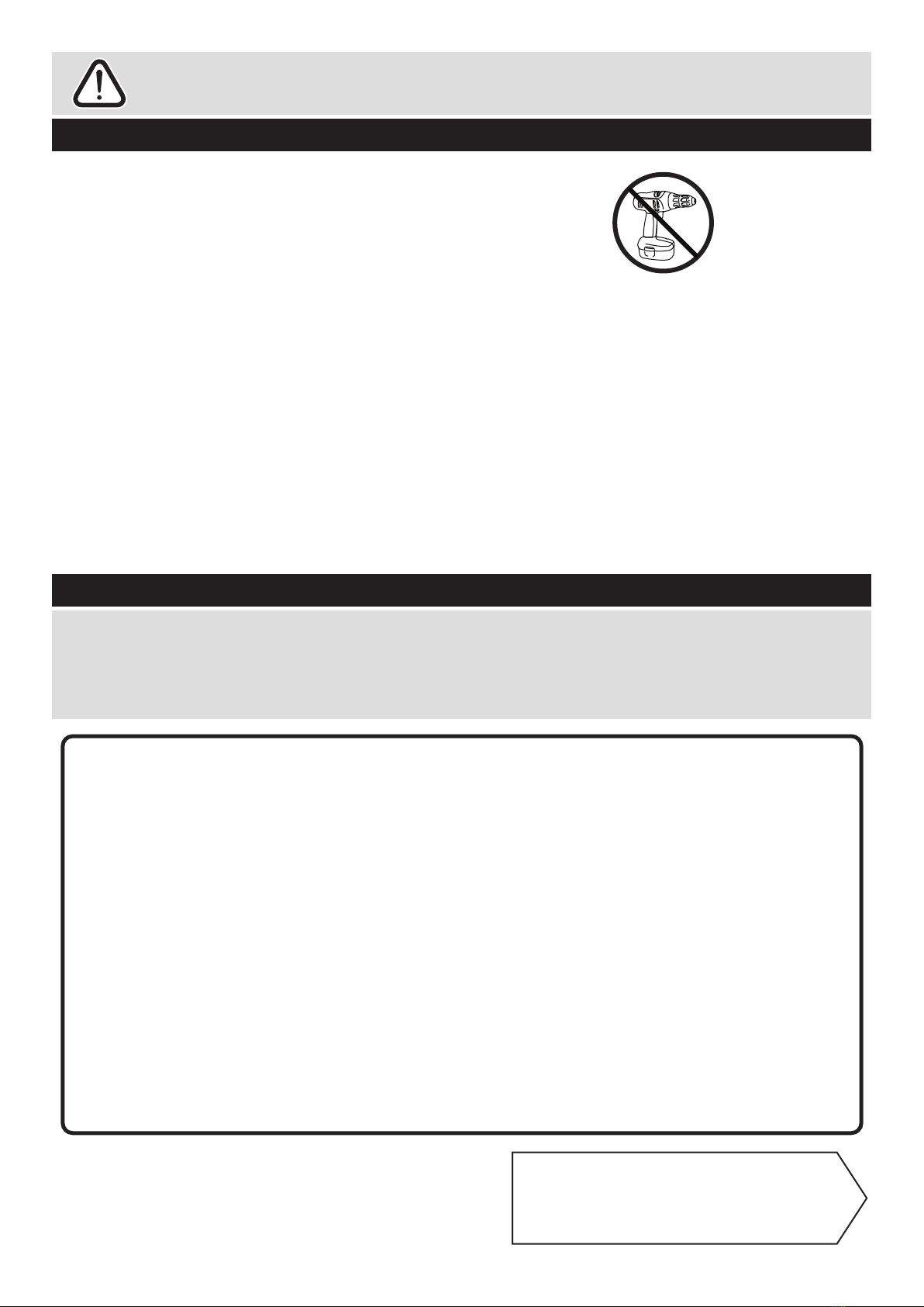
• We do not
recommend the
use of power
drill/drivers for
inserting screws,
as this could damage the unit.
Only use hand screwdrivers.
• Safety note: It is
recommended that this unit is
secured to a wall using the
bracket supplied.
• Dispose of all packaging
carefully and responsibly.
IMPORTANT INFORMATION ABOUT THIS PRODUCT
This product complies with the requirements of BS 7449:1991 and has been manufactured by
DECORATIVE PANELS FURNITURE LTD, TEESSIDE INDUSTRIAL ESTATE,
THORNABY-ON-TEES, CLEVELAND, TS17 9LT
.
The product code for this unit and the item code(s) for the glass components are listed in the Assembly
Instructions along with a description of the type of glass used. All clear/tinted glass complies with the
requirements of BS 6206 Class A. All mirrors comply with the requirements of BS 6206 Class C. If the
glass component contained in this unit is chipped or broken consult the furniture manufacturer, retailer,
or agent with regard to obtaining a manufacturing specification and shape for replacement glass
quoting the unit description and batch number or date of manufacture.
Do not place very hot or very cold items against or in close proximity to glass surface(s) unless
adequately thick insulating material is used to prevent such items coming in contact with the glass.
Do not strike the glass with hard or pointed items.
Do not sit or stand upon horizontal glass surfaces.
When cleaning glass panels use a damp cloth or leather with washing up liquid or soft soap if
necessary - do not use washing powders or any other substance containing abrasives since these
substances scratch glass.
If stated in the instruction leaflet, it is essential that this unit is fixed to a wall.
KEEP THESE INSTRUCTIONS FOR FUTURE USE
Components - Panels
Please check you have all the panels listed below
2
1 2
80%
x 3
If you have damaged or missing components, call the
Customer Helpline: 08456 400800 quoting the reference
numbers below
4
3Top (D2721A)
(690 x 494mm)
5
Horizontal (D2722A)
(654 x 456mm) x 2
Back (X1890-674)
(1890 x 674mm)
Plinth (D2723A)
(654 x 86mm)
6
89
Hanging Rail (FHR646)
(646mm long)
7
Right Side (D2719A)
(1981 x 458mm)
Left Side (D2720A)
(1981 x 458mm)
Rail (D2724A)
(654 x 86mm) x 2
Mirror Door (D2725MA)
(1888 x 337mm) x 2
(Mirror - SG24
1817 x 260mm
Safety Back SAR)
Please check you have all the fittings listed below
3
Components - Fittings If you have damaged or missing components, call the
Customer Helpline: 08456 400800 quoting the reference
numbers below
Note: The quantities below are the correct amount to complete the assembly. In some cases
more fittings may be supplied than are required.
A
Wooden dowel (F22) x 18
B
Metal dowel (F901) x 14
C
D E
Large locking
nut (F900) x 14
F
G H I
L
Nail (F51) x 35
Ruler - Use this ruler to help correctly identify the screws
mm 10 20 30 40 50 60 70 80 90 100 110 120 130 140 150 160 170
J
M
K
see malibu fitment mk2 for large number of panels and fittings
Rail Holder
(F891) x 2
19mm Screw (F461) x 4
13mm Screw (F63) x 1613mm Screw (F79) x 1
Bracket (F327) x 1
Handle (F274) x 2
Tools required
Rule
Scissors
Spirit
level
Hammer Bradawl
Eye protection
(when using a
hammer or drill)
Cross-head
screwdriver
Step
ladder
Electric drill
(only use
when drilling
into walls)
Square
mm 10 20 30 40 50 60 70 80 90 100
40mm Screw (F910) x 4
Hinge (F518) x 6
Hinge plate
(F523) x 6
N
Plastic Nail (F91) x 4
Finished
front edge
A
A
A
A
Assembly Instructions
4
If you have damaged or missing components, call the
Customer Helpline: 08456 400800 quoting the reference
numbers below
Step 1
Step 2
Prepare the left side
Tap 2 wooden dowels
into the left side .
Note: Wooden dowels
must not stick out from
the edge by more than
10mm or they may
damage other panels.
Screw 7 metal dowels
into the left side .
Note: Tighten the metal
dowels up fully against
the panels.
Fit 3 hinge plates onto
the left side , making
sure that the slot is
facing towards the
finished front edge.
Fit the rail holder to
the left side using 2
screws .
To fit the rail holder, screw
through its top hole and into the
shallow mark hole drilled in the
panel. Make sure that it is fitted
straight, in line with the panel
edges and then fit another
screw using the lower hole.
Prepare the right side
Tap 2 wooden dowels
into the right side .
Screw 7 metal dowels
into the right side .
Fit 3 hinge plates onto
the right side , making
sure that the slot is
facing towards the
finished front edge.
Fit the rail holder to
the right side using 2
screws .
A
10mm
A
K
B
B
1
1
1
K
A
B
2
2
2
K
K
K
K
B
B
B
B
B
B1
K
K
K
K
B
B
B
B
B
Finished
front edge
2
H
I
H
I
I
1
H
I
2
H
I
HH
I
HH
B
B
B
Finished
front edge
Finished
top edge
A
Finished
front edge
Finished
front edge
A
Assembly Instructions
5
Step 3
Step 4
Finished
front edge A
A
A
C
C
C
C
Prepare the 2
horizontals
Tap 4 wooden dowels
into each horizontal .
Insert 4 large locking
nuts into each
horizontal .
Note: The arrow on the
locking nut must point
towards the hole in the
edge of the panel.
A
4
4
C
Cx 2
4
4
4
Fit the 2 horizontals
to the right side
Push the 2 horizontals
onto the right side .
Use a screwdriver to
tighten the 2 large
locking nuts fitted
each horizontal .
Note: Turn the large
locking nuts as far as
they will go - more than
1/2 a turn.
Step 5
2
4
C
C
4
2
A
C
C
A
A
C
C
Prepare the plinth and
the 2 rails
Tap 2 wooden dowels
into the plinth and
each of the 2 rails .
Insert 2 large locking
nuts into the plinth
and each of the 2 rails
. .
Note: The plinth and the
2 rails can have a plain
chipboard surface.
A
5
6
6
5
C
5
6
B
C
Note: The rails have a finished top edge.
Plain
chipboard
surface
x 2
Plain
chipboard
surface
Finished
front edge
Assembly Instructions
6
Step 6
2
Finished
top edge
5
6
Fit the plinth and rails
Push the plinth onto
the right side .
Use a screwdriver to
tighten the large locking
nut fitted to the plinth
. .
Push the 2 rails onto
the right side .
Use a screwdriver to
tighten the large locking
nuts fitted to the 2
rails .
2
C
5
5
2
C
6
6
Note: Support the plinth
and the rails until the left
side has been fitted in
the next step.
5
6
Step 7
Fit the left side
Push the left side
onto the assembly.
Use a screwdriver to
tighten the 7 large
locking nuts fitted to
the horizontals , the
plinth and the 2 rails
. .
1
C
4
5
6
Note: The 2 rails have
a finished top edge.
1
4
4
Finished
top edge
6
6
E
E
E
E
Assembly Instructions
7
Step 8
Step 9
Fit the top and the
plastic nails
Push the top onto
the assembly and secure
it to the sides and
using 4 screws .
Tap 2 plastic nails
into the bottom edge of
each of the sides and
. as shown.
3
1 2
E
2
b:
Fit the back
a: Square up the unit by
making sure that
measurement x to x
equals y to y.
b: Place the back
onto the unit, making
sure it is pushed up
against the top .
Nail around the
outside edges of the
back .
Note: Nails should be
spaced about 150mm
apart.
Stand the unit up for
the next step.
9
3
D
The measurement from top corner X to bottom corner X must be
equal to the measurement from top corner Y to bottom corner Y
a:
y
y
x
D
Warning: The
unit is heavy.
Lift with care.
3
9
1
3
Finished
front edge
9
N
N
N
1
2
N
N
x
Assembly Instructions
8
Step 10
Step 11
7
I
Fit the hanging rail
Push the hanging rail
. into the rail holders
fitted to the side panels.
7I
L
HH
90
L
L
HH
L
HH
Prepare the 2 doors
Push fit 3 hinges into
each of the doors .
Secure each hinge with
2 screws .
Note: Before securing
with the screws, make
sure that the hinges are
positioned at 90 degrees
with the edge of the
door.
H
L
8
8
x 2
7
Warning:
Glass! Handle
with care
Assembly Instructions
9
Step 12
Fit doors and handles
Note: The easiest way to
attach each door is
to fit the top hinge first,
then align and fit the
other hinges.
a: Push the hinge
onto the front part of the
hinge plate .
The recess at the bottom
of screw B goes into the
slot in the hinge plate.
b: Keep the hinge
FLAT against the hinge
plate as you slide it
across as far as it will go.
Tighten screw A.
c: The hinge must be
flat against the hinge
plate prior to any
adjustment.
d: The hinge must
NOT be AT AN ANGLE
to the hinge plate
when assembled.
This would indicate that
the recess at the bottom
of screw B had not
located in the slot in the
hinge plate and the hinge
would not be secure.
Remove the hinge from
the hinge plate and then
re-assemble being
careful to follow
instructions a-c.
e: Attach a handle to
each door using 2
screws .
L
L
L
K
K
K
L
K
M
F
8
8
e:
a: b:
c: d:
K
L
K
K
B
K
L
L
L
A
L
K
B
F
M
F
8
M
8
Warning:
Glass! Handle
with care
Assembly Instructions
10
Step 13
Adjust the doors if
needed
a: Before adjusting the
doors, use a spirit level
to check the base (or
top) of the unit is level,
front-to-back and
side-to-side in the 3
positions shown.
Use suitable packing
pieces (not supplied) to
make the unit level
BEFORE making any
adjustment to the hinges,
as shown.
b: Height adjustment.
Loosen screws A on
hinge plates and move
door up or down as
required.
Retighten screw A.
c: Forward and Back
adjustment.
Loosen screw B on hinge
plate and move door in
or out as required.
Retighten screw B.
d: Sideways
adjustment.
To move door ‘out’
loosen screw C.
To move door ‘in’ tighten
screw C.
b:
c:
d:
a:
A
A
B
C
Assembly Instructions
11
If you need help or have damaged or missing parts, call the Customer Helpline: 08456 400800
and quote the reference numbers on the component pages.
Argos Ltd, 489-499 Avebury Boulevard, Central Milton Keynes, MK9 2NW
ALR2965
Step 14
Top of Unit
WALL
WALL
Back of Unit
Fit the bracket
To prevent possible
overbalancing, we
recommend that this unit
is secured to a suitable
wall by use of the
bracket fitted to the
top of the unit.
Fixings are not supplied,
as they will need to suit
the wall type and the
length of screw will
depend on the distance
from the back of the unit
to the wall.
Fix the bracket
loosely onto the top of
the unit using screw
and mark the wall for the
wall fixing.
Swivel the bracket
away from the wall and
drill a hole in the wall
using a suitable drill bit
and fit your wall fixing.
Swivel the bracket
back and fix the bracket
to the wall, then tighten
screw .
Note: Take care when
drilling the wall that you
do not drill into any
pipes, wires etc.
If in doubt, consult an
expert.
Warning: The
unit is heavy.
Lift with care.
Assembly is complete
J
J
G
J
J
G
J
G
J
J
IMPORTANT
If you have purchased the Cheval Overbed
Cupboards, you will need to fix them to the
wall BEFORE you fix the Robe to the wall.