ARRI Orbiter User manual

Arnold & Richter Cine Technik GmbH & Co. Betriebs KG, Arriweg 17, D-83071 Stephanskirchen, Germany | www.arri.com
L5.0033503
Short Instruction
Kurzanleitung
Guide Rapide
⡆ㄝ᭩
08 / 2020
⡆ㄝ᭩

2
1Yoke 9Antenna (wireless DMX) 17 Control Panel 25 DMX out
2Spigot (28 mm Junior Pin) 10 Communication Interface
(Lemo 5-pin) 18 Focus Handle 26 Ethernet Connector (RJ45)
3Upper Handle 11 Digital Optics Interface
(5-pin) 19 Mains in and out 27 Ethernet Connector (RJ45)
4Protective Cap 12 Light Aperture with
protection glass 20 Battery Connector
48 - 52 V ៑ 28 Status LED
5Rubber Feet 13 Guide for Locking Pin 21 Tilt Lock 29 SYNC Connector (SMA)
6Locking Slider 14 Safety Loop Attachment 22 SD Card Slot 30 Reset Button
7Quick Release Lever 15 Ambient Light Sensor 23 USB Ports
8Yoke Bracket 16 Connector for Control Panel
Extension Cable 24 DMX in
1Haltebügel 9Antenne für drahtloses DMX17 Steuerung 25 DMX Ausgang
228 mm Aufhängezapfen 10 Kommunikationsanschluss
(Lemo 5-pol.) 18 Einstellgriff 26 Netzwerkanschluss RJ45
3Tragegriff 11 Digitale Optikschnittstelle
(5-polig) 19 Netzspannungseingang und
-ausgang 27 Netzwerkanschluss RJ45
4Schutzkappe 12 Lichtaustrittsöffnung mit
Schutzscheibe 20 Akkupack-Anschluss
48 - 52 V ៑28 Status-LED
5Standfüsse 13 Aufnahme Sicherungsstift 21 Bügelklemmung 29 SYNC-Anschluss (SMA)
6Verriegelung für Zubehör 14 Aufnahme Sicherungsseil 22 Einschub für SD-Karte 30 Reset-Taste
7Schnellspannverschluss 15 Umgebungslichtsensor 23 USB-Anschlüsse
8Bügelaufnahme 16 Anschluss für die Leitung
der Steuerung 24 DMX Eingang

3
3
4
5
6
9
Orbiter (delivery state)
Orbiter (Lieferzustand)
7
8
11
10
12
Quick Lighting Mount QLM
13
27
23 25 26
19
24
20
22
29
28 30
Connector Panel
Anschlussfeld
2
114
16
17
18
19
20
15
21
Orbiter with manual yoke & control panel*
Orbiter mit man. Bügel und Steuerung*
*Yoke & control panel must be ordered separately
*Bügel und Steuerung müssen separat bestellt werden
Safety Loop Attachment
Aufnahme Sicherungsseil
ARRI, the ARRI Logo, ARRIMAX, ARRISUN, EB, LiOS, L-Series, MAX Technology, M-Series, Orbiter, POCKETPAR,
Quick Lighting Mount, True Blue, SkyPanel, SKYPANEL, T 12 and T 24 are registered trademarks of the Arnold & Richter
Cine Technik GmbH & Co. Betriebs KG.

4
Intended use
This product is intended to illuminate persons and objects. It is
conditionally weatherproof.
Yoke, control panel, optics and mains cables are not included
and must be ordered separately.
Always follow the safety information.
Any usage other than described above is not permitted and can
damage the product and lead to associated risks such as short-
circuit, fire, electric shock, etc. You are not allowed to modify the
product.
Safety Instruction
NOT FOR HOUSEHOLD USE
The Orbiter luminaire is intended for professional use
and may only be operated by qualified persons.
READ THE MANUAL
Please read all instructions carefully before using the
product for the first time. The following text contains
important information for safe handling.
DANGER OF LIFE – MAINS VOLTAGE!
Unplug the mains cable before any service or main-
tenance work or when the fixture is not in use.
• Do not open the housing of the Orbiter. For safe operation,
the housing must be completely closed at all times.
• Always earth the fixture electrically. Only use TN- or TT one
phase power supplies and a power plug according to IEC
60309-1 or a similar national standard.
• Use suitable, genuine ARRI mains cables only. The use of
third-party mains cables is on your own risk.
• Always follow the instructions of the connector manufactur-
er when installing a connector on the mains cable.
• Do not use any cable to hold, move or suspend the device.
• Check the mains cable prior to every operation for damage.
• In case of visible damage to cables or housings, the device
may not be operated any longer. Damaged components of
the housing must be replaced by a certified ARRI service
center.
• Do not cover the ventilation slots of the device. Unobstruct-
ed airflow is required for effective cooling.
• Avoid direct illumination by other luminaires or other heat
sources.
CAUTION – HIGH BEAM INTENSITY!
Do not look into the active light source of the Orbiter.
CAUTION - OPTICAL RADIATION
The fixture emits optical radiation during operation.
Always observe the minimum distance to persons
and objects.
CAUTION - HOT SURFACE
The fixture becomes up to 75° C (167° F) hot during
operation. Do not touch the fixture during operation.
Let the fixture cool down completely before handling.
CAUTION - BREAKING GLASS
Protection glass: Replace a broken pro-
tection glass immediately. Do not use a
lamphead with broken protection glass.
Always observe the minimum distances to persons and flamma-
ble objects given on the type plate. Always observe the maxi-
mum tilt angle.
GENERAL NOTES
• For your personal safety, please observe the safety
instructions and warnings given here and in the „Safety and
Installation Manual“ (L5.0021114). The manual is available
for download free of charge on the website www.arri.com.
• Observe all common and local safety regulations.
• Please keep these instructions for possible subsequent
owners.
• Please dispose the packing material at your local recycling
center for environmental protection.
• Defective products shall be disposed appropriately. For fur-
ther information please ask your ARRI dealer or your local
authorities.
• Use only original ARRI spare parts and accessories.
To Secure the Device and its Accessories
• When mounted in a hanging position or above persons, use
a suitable safety cable to prevent the Orbiter and the
attached accessories against falling when the primary
mounting method fails.
• The safety cable and its connecting elements must be rated
at a minimum load of 10 times the weight of the device and
all attached accessories.
• Lead the safety cable through the safety loop attachment
(14) and the structure the device is mounted to.
• The safety cable must be kept short.
• The locking slider (6) must snap in the guide hole of the
changeable optic or the optical accessory.
• Attach an appropriate rated safety cable to the safety hole
in the changeable optic or optical accessory. Affix the safety
cable to the structure the fixture is mounted to or the upper
handle (3) of the Orbiter.
• Tripods must be set up in a stable way and must be rated to
carry the required load. Please observe the weight of the
accessories and the cables. Please refer also to the leaflet
„Operating your ARRI Lampheads Safely“ L5.40731.E.
Basic Functions
MOUNTING
The Orbiter must be mounted on its yoke (1) in perpendicular
standing position or hanging position. Never apply lateral load to
the stirrup. Always insert the 28 mm spigot (2) into the bushing
of a suitable stand or a suitable clamping system and fix and se-
cure the spigot afterwards.
ENGLISH

5
5
PAN AND TILT
• Swivel the Orbiter after loosening the screw of the stand or
the clamping system. The tilt angle can be adjusted by
releasing both tilt locks (21). After the adjustment of the pan
angle and the tilt angle, the screws respectively clamps
must be fastened again.
TO ADJUST THE BEAM ANGLE
• The beam angle can be adjusted by using different change-
able optics which are available separately from ARRI.
USE OF CHANGEABLE OPTICS
Changeable optics like open face, domes and softboxes can be
connected to the device using the Quick Lighting Mount. The
communication port identifies the optics that been connected to
the luminaire.
There is no light output with mounted protective cap (4) or when
no optic or optical accessory is mounted to the Orbiter.
To mount a changeable optic or optical accessory to the Orbiter:
• Switch the Orbiter off. Remove the protective cap (4) or the
accessory as described below.
• Align the bayonet catch of the accessory with the recesses
of the quick lighting mount ring and insert the accessory.
• Turn the accessory clockwise until the accessory locking
tab audibly engages. Check that the accessory is securely
fastened by turning it counterclockwise. It must not be pos-
sible to turn the accessory.
To remove an optical accessory from the Orbiter:
• Switch the Orbiter off.
• Hold the accessory firmly. Press the locking slider (6) in-
wards.
• Turn the accessory counterclockwise and remove it from
the Quick Lighting Mount.
• Mount another accessory or the protective cap as described
above.
DMX INTERFACE
The Orbiter is equipped with two locking, 5-pin XLR connectors
(24 and 25) for the DMX / RDM data input and throughput.
USB INTERFACE
The Orbiter is equipped with two USB A ports (23, load capacity
1500 mA and 500 mA) and one USB C port. The USB A port can
be used for uploading new firmware using a FAT32 formatted
USB 1.0 / 2.0 memory stick.
The USB C port can be used for service purpose.
ETHERNET CONNECTOR
The Orbiter is equipped with two RJ45 Ethernet connectors (26
and 27).
The Ethernet signal can be daisy-chained as the Orbiter acts like
a switch in an Ethernet network. The interface can be used for
control, uploading new firmware, setting parameters and service
purpose using the ARRI lighting service manager.
SD CARD SLOT
The SD card slot (22) accepts standard SD / SDHC cards.
WIRELESS DMX INTERFACE
The Orbiter equipped with a LumenRadio wireless DMX (CRMX)
receiver. It can communicate DMX and RDM.
POWER-ON AND OPERATION
By applying the mains power to the Orbiter, the Orbiter starts
lighting after a short startup time with the same setting which had
been active at its last switch off.
The Orbiter can now be controlled over the DMX interface, the
Ethernet interface or by the removable control panel (17).
Operating Modes
WHITE LIGHT
The Orbiter generates white light with an optimized color
rendition or high output with reduced color rendition. The color
temperature and the green / magenta point can be continuously
adjusted.
COLORED LIGHT
The Orbiter generates colored light. The color tone (hue) and the
color saturation can be adjusted continuously. At very low color
saturation, the Orbiter generates white light without an optimized
color rendition.
The full spectrum operating modes can be found in the Orbiter
user manual.
Control Panel
The Orbiter can be equipped with a removable control panel
which must be ordered separately. The user interface is very in-
tuitive and easy to understand.
CAUTION - DANGER OF INJURY
Always check the proper seat of the control panel af-
ter applying it to the Orbiter. A control panel falling off
could cause severe injury and damages.
The control panel user manual contains more detailed informa-
tion about the features and functionalities of the control panel
and is available on the website www.arri.com.
Firmware
The latest firmware and the ARRI Lighting Service Manager
(ALSM) software tool are located in the download area of our
website www.arri.com for free download.
Check regularly on the ARRI Orbiter website if a new firmware
version is available for the Orbiter. For best performance we
strongly recommend to use the luminaire with the latest firmware
available.
To Replace the Light Source
The light source contained in this luminaire is replaceable by a
service agent or a similar qualified person. If the light source has
reached the end of its operational life or if the light source fails
before it reached the end of its specified operational life, please
contact the manufacturer or his service agent or a similar quali-
fied person.
User Manual
The Orbiter user manual contains more detailed information
about the features and functionalities of the device. Please visit
the website www.arri.com to download the user manual and
much more information about the Orbiter free of charge.
ENGLISH
Design and specifications are subject to change without notice
ARRI Service
In case of technical problems please visit us at
www.arri.com
Arnold & Richter Cine Technik GmbH & Co. Betriebs KG
Global Application & Services
Arriweg 17
D-83071 Stephanskirchen
Germany

6
Bestimmungsgemäße Verwendung
Das Produkt dient zur Beleuchtung von Personen und
Gegenständen. Es ist eingeschränkt witterungsbeständig.
Haltebügel, Steuerung, Optik und Netzkabel sind nicht im Liefer-
umfang enthalten und müssen separat bestellt werden.
Befolgen Sie unbedingt die Sicherheitshinweise!
Eine andere als die beschriebene Verwendung führt zur Be-
schädigung dieses Produktes. Dies ist mit Gefahren, wie z.B.
Kurzschluss, Brand, elektrischer Schlag etc. verbunden. Das
Produkt darf nicht geändert bzw. umgebaut werden.
Sicherheitshinweise
NUR FÜR PROFESSIONELLEN GEBRAUCH
Der Orbiter LED-Scheinwerfer ist für den professio-
nellen Einsatz bestimmt. Er darf nur von befähigten
Personen betrieben werden.
BEACHTEN SIE DIE ANLEITUNG
Bitte lesen Sie alle Anleitungen sorgfältig vor der ers-
ten Inbetriebnahme. Der folgende Text enthält wich-
tige Hinweise für die sichere Handhabung.
VORSICHT NETZSPANNUNG –
LEBENSGEFAHR!
Trennen Sie das Gerät allpolig vom Netz, bevor Sie
Reparatur- oder Wartungsarbeiten ausführen oder
das Gerät nicht in Betrieb ist.
• Öffnen Sie das Gehäuse des Orbiters nicht. Der sichere Be-
trieb des Scheinwerfers ist nur bei vollständig geschlosse-
nem Gehäuse gewährleistet.
• Das Gerät muss elektrisch geerdet werden und darf nur als
Einphasen-Betriebsmittel an einem TN- oder TT-Stromver-
sorgungssystem mit einen Stecker nach IEC 60309-1 oder
vergleichbarer nationaler Norm angeschlossen werden.
• Verwenden Sie original ARRI Netzleitungen. Die Verwen-
dung anderer Netzleitungen geschieht auf eigene Gefahr.
• Beachten Sie bei der Montage eines Netzsteckers immer
die Montagehinweise des Steckerherstellers.
• Verwenden Sie keine Leitungen zum Halten, Bewegen
oder Aufhängen des Orbiters.
• Prüfen Sie die Netzleitung des Scheinwerfers vor jedem
Gebrauch auf sichtbare Schäden.
• Verwenden Sie den Scheinwerfer bei sichtbaren Beschädi-
gungen nicht. Schäden müssen durch ein zertifiziertes
ARRI Service-Center behoben werden.
• Decken Sie die Lüftungsöffnungen des Scheinwerfers nie-
mals ab. Der Orbiter muss frei umströmt werden können,
um die Kühlung zu gewährleisten.
• Vermeiden Sie die Bestrahlung durch andere Scheinwerfer
und andere Wärmequellen.
VORSICHT – HOHE LICHTSTÄRKE!
Nicht in die aktive Lichtquelle des Orbiters
starren.
VORSICHT - OPTISCHE STRAHLUNG
Das Gerät emittiert während des Betriebes optische
Strahlung. Beachten Sie immer die Sicherheitsab-
stände zu Personen und Objekten.
VORSICHT - HEISSE OBERFLÄCHE
Das Gerät wird während des Betriebes bis zu 75° C
warm. Berühren Sie das Gerät während des Betrie-
bes nicht. Lassen Sie es vollständig abkühlen, bevor
Sie es berühren.
VORSICHT - GLASBRUCH
Schutzscheibe: Eine zersprungene
Schutzscheibe ist unverzüglich zu erset-
zen. Geräte mit zersprungener Schutz-
scheibe dürfen nicht verwendet werden.
Halten Sie die auf dem Typenschild beschriebenen Mindest-
abstände zu Personen und brennbaren Werkstoffen ein. Beach-
ten Sie die zulässigen Neigungswinkel.
Allgemeine Hinweise
• Beachten Sie die Sicherheits- und Warnhinweise in dieser
Anleitung und den „Sicherheits- und Installationshinweisen“
(L5.0021113). Sie stehen zum kostenlosen Download auf
der Webseite www.arri.com zur Verfügung.
• Beachten Sie alle allgemeinen und örtlichen Sicherheits-
vorschriften.
• Bewahren Sie diese Anleitung für Nachbesitzer auf.
• Entsorgen Sie das Verpackungsmaterial der Umwelt
zuliebe bei einer geeigneten Entsorgungsstelle.
• Auch defekte Geräte müssen sachgerecht entsorgt werden.
Weitere Informationen hierzu erhalten Sie von Ihrem
ARRI-Händler und Ihrer Gemeinde- oder Stadtverwaltung.
• Verwenden Sie nur Originalersatzteile und Original-
Zubehör von ARRI.
Sicherung des Scheinwerfers und Zubehörs
• Bei hängendem Betrieb und beim Betrieb über Personen
müssen Sie den Orbiter und das verwendete Zubehör mit-
tels eines zugelassenen Sicherungsseils gegen Herabfal-
len sichern.
• Das Sicherungsseil und seine Verbindungselemente
müssen mindestens für das 10-fache Gewicht der zu
sichernden Geräte ausgelegt sein.
• Führen Sie das Sicherungsseil durch die Aufnahme für das
Sicherungsseil (14) und um die den Scheinwerfer tragende
Struktur.
• Halten Sie das Sicherungsseil so kurz wie möglich.
• Der Verriegelungsstift (6) muss in die Führungsbohrung des
optischen Zubehörs einrasten.
• Jedes Zubehör muss mit einem geeigneten Sicherungsseil
gesichert werden. Führen Sie das Sicherungsseil durch den
Ankerpunkt des Zubehörs zur den Scheinwerfer tragenden
Struktur oder um den oberen Tragegriff (3) des Orbiter.
• Stative müssen standsicher aufgestellt und für die Last
ausgelegt sein. Beachten Sie hierbei das Gewicht des
Zubehörs und der Kabel. Lesen Sie hierzu auch die
Hinweise im „Sicherheitsmerkblatt für ARRI-Scheinwerfer“
L5.40731.E.
Grundfunktionen
BEFESTIGUNG
Der Orbiter darf nur an seinem Haltebügel (1) senkrecht stehend
oder hängend befestigt werden. Schieben Sie den 28 mm Auf-
hängezapfen (2) in die Hülse eines passenden Stativs oder ei-
ner passenden Haltevorrichtung und klemmen Sie ihn fest.
Sichern Sie den Zapfen gegen Herausfallen.
DEUTSCH

7
7
DREHEN UND NEIGEN
Sie können den Orbiter nach Lösen der Schraube am Stativ
oder der Haltevorrichtung drehen. Verändern Sie die Neigung
nach Lösen beider Bügelklemmungen (21). Ziehen Sie alle
Schrauben und die Bügelklemmungen nach dem Einrichten des
Orbiters fest an.
EINSTELLEN DES STREUWINKELS
Der Streuwinkel kann durch Verwendung verschiedener
Optiken, die als Zubehör erhältlich sind, eingestellt werden.
VERWENDUNG VON WECHSELOPTIKEN
Wechseloptiken, wie Open Face, Dome Optiken sowie Softbo-
xen werden in den Quick Lighting Mount (QLM) Ring eingesetzt
und verriegelt. Ein Kommunikationsport informiert den Orbiter,
welches Zubehör eingesetzt wurde.
Mit montierter Schutzkappe (4) oder ohne montierte Wechselop-
tik oder optisches Zubehör erzeugt der Orbiter kein Licht.
Montage einer Wechseloptik oder eines optischen Zubehörs:
• Schalten Sie den Orbiter aus. Entfernen Sie die Schutz-
kappe (4) oder das Zubehör, wie unten beschrieben.
• Richten Sie den Bajonettring des Zubehörs zu den Aus-
sparungen der Zubehöraufnahme aus und setzen Sie das
Zubehör ein.
• Drehen Sie das Zubehör im Uhrzeigersinn, bis die Verriege-
lung hörbar einrastet. Prüfen Sie den sicheren Sitz durch
Drehen des Zubehörs gegen den Uhrzeigersinn. Dies darf
nicht möglich sein.
Entfernen einer Wechseloptik oder eines optischen Zubehörs:
• Schalten Sie den Orbiter aus.
• Halten Sie das Zubehör gut fest. Drücken Sie die Verriege-
lungslasche nach innen.
• Drehen Sie das Zubehör bis zum Anschlag gegen den Uhr-
zeigersinn. Nehmen Sie es aus der Zubehöraufnahme.
• Montieren Sie ein anderes Zubehör oder die Schutzkappe,
wie oben beschrieben.
DMX-SCHNITTSTELLE
Der Orbiter verfügt über zwei 5-polige XLR-Verbinder (24 und
25) für den DMX / RDM Datenein- und -ausgang.
USB-SCHNITTSTELLE
Der Orbiter besitzt zwei USB A-Schnittstellen (23, Belastbarkeit
1500 mA und 500 mA) und eine USB C-Schnittstelle. Die USB
A-Schnittstellen dienen zum Aufspielen von Firmware über ei-
nen FAT32 formatierten USB 1.0 / 2.0 Memorystick.
Die USB C-Schnittstelle dient für Servicezwecke.
NETZWERKANSCHLUSS
Der Orbiter hat zwei RJ45 Netzwerkanschlüsse (26, 27).
Das Netzwerksignal kann durchgeschleift werden. Der Orbiter
verhält sich wie ein Switch in einem Ethernet-Netzwerk. Das In-
terface kann zur Steuerung des Orbiters, für das Aufspielen von
Firmware, die Einstellung von Betriebsparametern und für Ser-
vicezwecke mit Hilfe des ARRI Lighting Service Managers
ALSM verwendet werden.
SD KARTENEINSCHUB
Der SD Karteneinschub (22) akzeptiert SD / SDHC Karten.
DRAHTLOSES DMX INTERFACE
Der Orbiter ist mit einem LumenRadio Wireless DMX (CRMX)
Empfänger ausgestattet. Er unterstützt DMX und RDM.
EINSCHALTEN UND BETRIEB
Nach dem Anlegen der Netzspannung beginnt der Orbiter nach
kurzer Verzögerung mit derjenigen Einstellung zu leuchten, die
bei der letzten Abschaltung aktiv war.
Der Orbiter kann nun über die DMX-Schnittstelle, die RJ45-
Schnittstelle oder über die Steuerung (17) gesteuert werden.
Betriebsarten
WEISSLICHT
Der Orbiter erzeugt weißes Licht mit optimierter Farbwiederga-
be oder maximaler Helligkeit mit reduzierter Farbwiedergabe.
Die Farbtemperatur und die Grün / Magenta-Sättigung können
stufenlos eingestellt werden.
FARBIGES LICHT
Der Orbiter erzeugt weißes oder farbiges Licht. Der Farbton
(Hue) und die Farbsättigung (Saturation) können stufenlos ein-
gestellt werden. Bei sehr geringer Farbsättigung wird weißes
Licht mit nicht optimierter Farbwiedergabe erzeugt.
Die gesamte Bandbreite aller Betriebsarten ist in der Orbiter
Bedienungsanleitung aufgeführt.
Bedienteil
Der Orbiter kann mit herausnehmbarer Steuerung ausgestattet
werden. Diese ist nicht im Lieferumfang enthalten. Die Bedie-
nung ist sehr intuitiv und leicht verständlich.
VORSICHT - VERLETZUNGSGEFAHR
Prüfen Sie immer den korrekten Sitz der Steuerung
im Orbiter. Eine herausfallende Steuerung kann Ver-
letzungen und Sachschaden verursachen.
Weitere Informationen zu den Funktionen und Eigenschaften
des Bedienteils finden Sie in der Bedienungsanleitung für die
Steuerung. Sie steht zum kostenfreien Download auf der ARRI
Website www.arri.com zur Verfügung.
Firmware
Die neueste Firmware sowie den ARRI Lighting Service
Manager ALSM finden Sie im Download-Bereich der ARRI Web-
site www.arri.com zum kostenlosen Download.
Prüfen Sie regelmäßig auf der ARRI Orbiter Website, ob neue
Firmware für den Orbiter verfügbar ist. Für beste Leistung emp-
fehlen wir, den Scheinwerfer immer mit der neuesten Firmware
zu verwenden.
Hinweis zum Ersetzen des Leuchtmittels
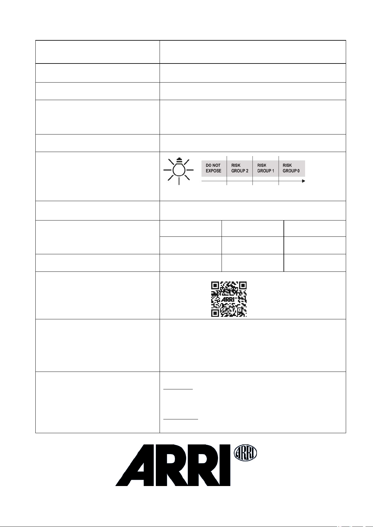
Die Lichtquelle dieser Leuchte darf nur durch den Hersteller der
Leuchte oder einen von ihm beauftragten Service-Techniker
oder einer vergleichbar qualifizierten Person ersetzt werden.
Wenn die Lichtquelle ihre Lebensdauer erreicht hat oder die
Lichtquelle vor Erreichen der angegebenen durchschnittlichen
Lebensdauer ausfällt, wenden Sie sich bitte an den Hersteller
der Leuchte oder einen von ihm beauftragten Service-Techniker
oder eine vergleichbar qualifizierte Person.
Bedienungsanleitung & weitere Information
Die Bedienungsanleitung enthält ausführliche Informationen
über die Merkmale und Funktionen des Gerätes. Diese und viele
weitere Informationen stehen zum kostenfreien Download auf
der ARRI Website www.arri.com zur Verfügung.
DEUTSCH
Technische Änderungen vorbehalten.
ARRI Service
Bei technischen Problemen besuchen Sie bitte
www.arri.com
Arnold & Richter Cine Technik GmbH & Co. Betriebs KG
Global Application & Services
Arriweg 17
D-83071 Stephanskirchen
Deutschland

Specification / Technische Daten Orbiter
Mains Input - AC Input
Netzspannungseingang
100 - 240 V~, 50/60 Hz
max. throughput current 15 A
max. Belastbarkeit des Netzspannungsausgangs 15 A
DC Input
Batteriespannungseingang Input DC 48 V - 52 V៑
Spannungseingang 48 V - 52 V៑
Power Consumption
Leistungsaufnahme 400 W nom.
500 W max.
Ingress Protection
Schutzart
IP24 with Orbiter rain cover, acceptable inclination +75° to -90°
IP20 without Orbiter rain cover, acceptable inclination +90° to -90°)
IP24 mit Orbiter Regenhaube, zul. Neigungswinkel +75° bis -90°
IP20 ohne Orbiter Regenhaube, zul. Neigungswinkel +90° bis -90°)
Protection Class
Schutzklasse I
Risk Group (blue light emission)
Risikogruppe (Blaulichtgefährdung)
Operating temperature
Zulässige Umgebungstemperatur
ta = - 4° F to +113° F
ta = -20° C - + 45° C
Dimensions (WxHxD)
Abmessungen (BxHxT)
State of delivery
Lieferzustand MAN P.O.
309 x 330 x 410 mm³
12.2 x 13.0 x 16.1 in³ 451 x 670 x 410 mm³
17.8 x 26.4 x 16.1 in³ 405 x 670 x 410 mm³
15.9 x 26.4 x 16.1 in³
Weight
Gewicht 11,7 kg
25.8 lbs 14,2 kg
31.3 lbs 14.9 kg
32.9 lbs
Firmware
The latest firmware can be found at www.arri.com/lios.
Certifications & Declarations of Conformity
Zertifizierungen & Konformitätserklärungen
CE, ICES, CB, ENEC, cNRTLus, FCC
pending: PSE, KC, SRRC and more
Note: This equipment has been tested and found to comply with the limits for a Class A digi-
tal device, pursuant to Part 15 of the FCC Rules. These limits are designed to provide rea-
sonable protection against harmful interference when the equipment is operated in a
commercial environment. This equipment generates, uses, and can radiate radio frequency
energy and, if not installed and used in accordance with the instruction manual, may cause
harmful interference to radio communications. Operation of this equipment in a residential
area is likely to cause harmful interference in which case the user will be required to correct
the interference at his own expense.
Packed items
Lieferumfang
Orbiter with antenna and protective cap, short instruction, leaflet „Operating your
ARRI Lampheads Safely“.
Not included: Yoke, control panel, optical accessories, cables.
Please find more information in the Orbiter Accessories Guide and on the Orbiter
website on www.arri.com.
Orbiter mit Antenne und Schutzkappe, Kurzanleitung, Broschüre „Allgemeine
Hinweise für ARRI Scheinwerfer“.
Nicht enthalten: Haltebügel, Steuerung, optisches Zubehör, Kabel.
Weitere Informationen finden sie im Orbiter Accessories Guide sowie auf der
Orbiter Website unter www.arri.com.
Distance 1.6 ft 15 ft 51.2 ft
Abstand 0,5 m 4,5 m 15,6 m
Other manuals for Orbiter
8
Table of contents
Other ARRI Lighting Equipment manuals

ARRI
ARRI Orbiter User manual

ARRI
ARRI Orbiter L2.0039421 User manual

ARRI
ARRI ARRISUN 12 Plus User manual

ARRI
ARRI M Series User manual

ARRI
ARRI M Series User manual

ARRI
ARRI L1.31230TA User manual

ARRI
ARRI DAYLIGHT 18/12 PLUS User manual

ARRI
ARRI L1.0009652 User manual

ARRI
ARRI ARRI D 5 User manual

ARRI
ARRI Orbiter L2.0039438 User manual

ARRI
ARRI SkyPanel User manual

ARRI
ARRI Orbiter How to use

ARRI
ARRI L7 User manual

ARRI
ARRI ARRIMAX 18/12 User manual

ARRI
ARRI SkyPanel S30 User manual

ARRI
ARRI Orbiter User manual

ARRI
ARRI L1.0001764 User manual

ARRI
ARRI EB MAX 1.8 User manual

ARRI
ARRI SkyPanel X Preliminary User manual

ARRI
ARRI ARRISUN 5 User manual