manuals.online logo
Brands
  1. Home
  2. •
  3. Brands
  4. •
  5. ARTHUR HOLM
  6. •
  7. Monitor
  8. •
  9. ARTHUR HOLM Dynamic DB2 Installation instructions manual

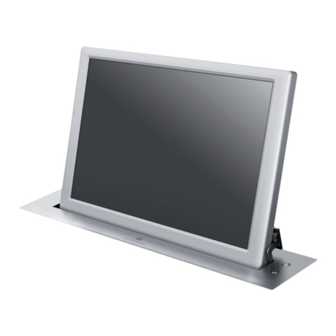
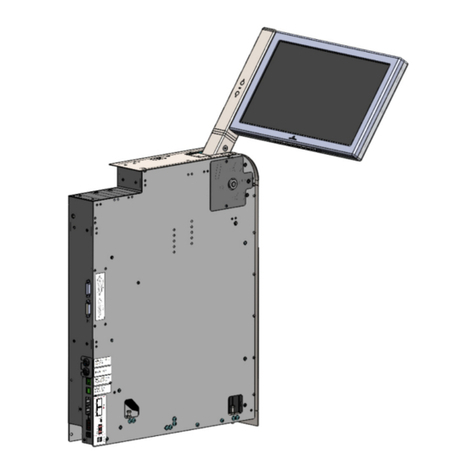
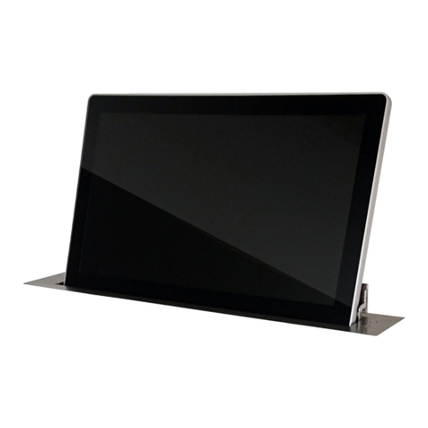
ARTHUR HOLM Dynamic DB2 Installation instructions manual

Mounting guide Dynamic DB2
638DOC001-01
- Mounting Guide Pg. 2-8
- Veneer Guide (Optional) Pg.9-12
Information
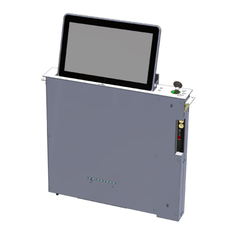
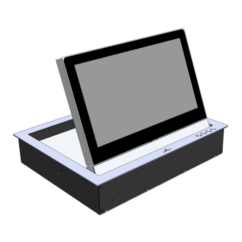
The DB2 monitor is prepared to be mounted from below the table.
Included in this version are all necessary brackets.
INTRODUCTION
2
ATTENTION
Manipulation of the product should be avoided, no stress should be applied to the product except from the
instructions given in this document. Cutting, drilling, soldering, adding of electrical and mechanical
components can cause danger and should be avoided by all mean. Not complying with these direction will
result in a lost of the Arthur Holm warranty. Albiral Display Solution S.L. shall not be held liable for any loss
or injury incurred as a result of modifications made to goods by anyone other than the supplier or the
supplier's authorised representative without the supplier's written permission. Such modifications shall be
deemed to terminate any further guarantee obligations. Compensation will not be paid for wages, loss of
profit, waste of time, packing and transport or any financial liability resulting from defects in the goods.
(Albiral Display Solutions shall not be liable for any loss or injury caused by negligence.)
PATTERN HOLE
Pattern hole dimensions for milling are specified in the corresponding drawing.
The milling of the furniture has to be done from bellow.
Mounting table brackets
Table Bracket
“A”
Front Side
Front Side
Mount the table brackets below the table using the holes indicated on the corresponding Pattern
Hole drawing. The screws (x6) are not supplied; The weight of the monitor is up to 25Kg.
PAY ATTENTION THAT THE BRACKETS ARE MOUNTED IN THEIR CORRESPONING SIDE
Front Side
3
View from below the table
Table Bracket
“B”
View from below the table
Mounting the monitor brackets
Mount the monitor brackets on their corresponding side using the supplied screws
Mount the vertical adjustment screws (2+2) on to the monitor bracket so that the tip of the screw is flushed with
the upper side of the monitor bracket.
4
(x4) Vertical Adjustment
Screws
Right Monitor bracket
“1”
Left Monitor bracket
“2” Front Side
(X4 Screw M6x20)
(X4 washer)
Checking assembly
Dimensions A and B in table brackets and in monitor brackets must be the same (+ 1mm).
If adjustment is necessary loosen 3+3 Table bracket screws, keeping always symmetry regarding to the
monitor hole in the table. Subsequently, tighten the table bracket screws.
Front Side
View from below the
table
View from above the
monitor
5
Front Side
Hanging the monitor
Mount 2+2 nuts on to both table
brackets as indicated on the
drawing.
Hang the monitor above nuts
6
Front Side
Centring the monitor
Air gap around the monitor have
to be 2mm [0,08]. Otherwise the
monitor could come in contact
with the table while opening and
be damaged
Tighten each nut gradually until
the monitor surface is levelled with
the table surface.
Front Side
View from above the
table
7
Front Side
Fine centring of the monitor
For adjusting the monitor closer or
further away from the table edge
loosen the four nuts half a turn
and move the monitor. When the
monitor is centred tighten the four
nuts.
IMPORTANT:
To secure the monitor tighten the four vertical adjustment screws.
Front Side
For adjusting the monitor to the
left or right loosen the table
screws half a turn and centre the
monitor. When the monitor is
centred tighten the six screws.
8
In case fine centering of the monitor is necessary
View from below the table
Veneer Guide (Optional)
The DB2 device is available in a special version that is prepared to be
mounted from below the table with a Veneer finishing on the top of the
monitor to match the table. The Veneer is not supplied
The Veneer can be placed in three ways (Dimensions are specified in the corresponding “Pattern Hole” document):
VENEER
INTRODUCTION
9
Veneer: The veneer thickness must be
5mm [0,16 –0,19]. A mechanized
blind hole will be necessary to hide
the touch button copper cylinder.
Veneer + Distance Plate: For Veneers
Thickness of 1mm [0,04] or less. It will be
necessary a Distance Plate to hide the
touch button copper cylinder.
Veneer
Distance Plate
Option2: Option3:
Option1:
Veneer: In order to adjust the plastic
touch button height, Venneer +
Glue/tape thickness must be previously
communicated.
Veneer
10
OPTION 1
- Veneer thickness must be accorded with factory
2. Clean the top surface of the metal monitor housing and the
bottom surface of the Veneer.
3. Glue the Veneer. Double-side tape or glue can be used
(depending on the kind of materials are going to be jointed).
1. Check if the Veneer fits perfectly with the monitor. To join both parts correctly it is important that the two surfaces
are touching each other in the whole length.
The pressure applied
must not exceed 1 Kg
evenly distributed on
monitor surface.
Veneer Guide (Optional)
INFORMATION 11
OPTION 2
-Distance Plate thickness must be the specified in the “Pattern Hole” document.
-Distance Plate material can’t be metallic. Wood or DM are advisable.
-Veneer material can’t be metallic.
2. Clean the top surface of the metal monitor housing and the bottom
surface of the Distance Plate.
3. Glue the Distance Plate. Double-side tape or glue can be used
(depending on the kind of materials are going to be jointed). The total
thickness of the Distance Plate + glue used can’t be thicker than
4,25mm [0,17].
1. Check if the Distance Plate fits perfectly with the monitor. The copper
cylinder can’t project outwards from the Distance Plate surface. If so,
the copper cylinder can be gently filed down till aligns with the
Distance Plate surface.
4. Clean the top surface of the Distance Plate and the
bottom surface of the Veneer.
5. Glue the Veneer. Double-side tape or glue can be
used (depending on the kind of materials are going to
be joint).
The total thickness of Veneer + glue used can’t be
thicker than 1mm [0,04].
The pressure applied
must not exceed 1 Kg
evenly distributed on
monitor surface.
Veneer Guide (Optional)
12
OPTION 3
-Veneer thickness and machining must be the specified in the “Pattern Hole” document.
-Veneer material can’t be metallic.
2. Clean the top surface of the metal monitor housing and the
bottom surface of the Veneer.
3. Glue the Veneer. Double-side tape or glue can be used
(depending on the kind of materials are going to be jointed).
The total thickness of the Veneer + glue used can’t be thicker
than 5,25mm [0,2].
1. Check if the Veneer fits perfectly with the monitor. To join both parts correctly it is important that the two surfaces
are touching each other in the whole length. If there is a gap between the Veneer and the monitor, check if the hole
depth in the Veneer is correct. To adjust them better the head of the cyllinder can be gently filed
The pressure applied
must not exceed 1 Kg
evenly distributed on
monitor surface.
Veneer Guide (Optional)
w w w. a r t h u r h o l m . c o m

Other ARTHUR HOLM Monitor manuals

ARTHUR HOLM AH1 Series User manual

ARTHUR HOLM

ARTHUR HOLM AH1 Series User manual

ARTHUR HOLM RISE AH12RI Wide User manual

ARTHUR HOLM

ARTHUR HOLM RISE AH12RI Wide User manual

ARTHUR HOLM AH 18D3 RHDGA RV User manual

ARTHUR HOLM

ARTHUR HOLM AH 18D3 RHDGA RV User manual

ARTHUR HOLM Dynamic3 AH15D3HDGA User manual

ARTHUR HOLM

ARTHUR HOLM Dynamic3 AH15D3HDGA User manual

ARTHUR HOLM Dynamic3 User manual

ARTHUR HOLM

ARTHUR HOLM Dynamic3 User manual

ARTHUR HOLM AH24DB2 User manual

ARTHUR HOLM

ARTHUR HOLM AH24DB2 User manual

ARTHUR HOLM DynamicX2Talk User manual

ARTHUR HOLM

ARTHUR HOLM DynamicX2Talk User manual

ARTHUR HOLM AH17D1HDA2F User manual

ARTHUR HOLM

ARTHUR HOLM AH17D1HDA2F User manual

ARTHUR HOLM AH10DB2 User manual

ARTHUR HOLM

ARTHUR HOLM AH10DB2 User manual

ARTHUR HOLM AH17S HDGA User manual

ARTHUR HOLM

ARTHUR HOLM AH17S HDGA User manual

ARTHUR HOLM AH24DB2 User manual

ARTHUR HOLM

ARTHUR HOLM AH24DB2 User manual

ARTHUR HOLM AH12D 2A User manual

ARTHUR HOLM

ARTHUR HOLM AH12D 2A User manual

ARTHUR HOLM DB2Share User manual

ARTHUR HOLM

ARTHUR HOLM DB2Share User manual

ARTHUR HOLM AH15D X2HDA User manual

ARTHUR HOLM

ARTHUR HOLM AH15D X2HDA User manual

ARTHUR HOLM AH12TX16GA User manual

ARTHUR HOLM

ARTHUR HOLM AH12TX16GA User manual

ARTHUR HOLM Dynamic 1H User manual

ARTHUR HOLM

ARTHUR HOLM Dynamic 1H User manual

ARTHUR HOLM Dynamic3Reverse User manual

ARTHUR HOLM

ARTHUR HOLM Dynamic3Reverse User manual

ARTHUR HOLM Gooseneck AH22NTT16 User manual

ARTHUR HOLM

ARTHUR HOLM Gooseneck AH22NTT16 User manual

ARTHUR HOLM Dynamic2 AH12D216A User manual

ARTHUR HOLM

ARTHUR HOLM Dynamic2 AH12D216A User manual

ARTHUR HOLM AH15D X2HDGA User manual

ARTHUR HOLM

ARTHUR HOLM AH15D X2HDGA User manual

ARTHUR HOLM DynamicX2 AH22DX216DGA User manual

ARTHUR HOLM

ARTHUR HOLM DynamicX2 AH22DX216DGA User manual

ARTHUR HOLM AH10 DA User manual

ARTHUR HOLM

ARTHUR HOLM AH10 DA User manual
ARTHUR HOLM DB2 Series User manual

ARTHUR HOLM

ARTHUR HOLM DB2 Series User manual

ARTHUR HOLM DB2 Series User manual

ARTHUR HOLM

ARTHUR HOLM DB2 Series User manual

Popular Monitor manuals by other brands

Sodiff SDM-1901S user manual

Sodiff

Sodiff SDM-1901S user manual

MAXFREE X2 user guide

MAXFREE

MAXFREE X2 user guide

Planar PL201M manual

Planar

Planar PL201M manual

Zenith ZVM-1380 Service manual

Zenith

Zenith ZVM-1380 Service manual

LG M4212C user guide

LG

LG M4212C user guide

Samsung U32J590UQ Series user manual

Samsung

Samsung U32J590UQ Series user manual

Iiyama ProLite TF1634MC user manual

Iiyama

Iiyama ProLite TF1634MC user manual

LG Flatron L1922P user guide

LG

LG Flatron L1922P user guide

Eiki EFD-52 owner's manual

Eiki

Eiki EFD-52 owner's manual

AOC 831S Specifications

AOC

AOC 831S Specifications

JVC DT-E17L4G instructions

JVC

JVC DT-E17L4G instructions

Dell E157FPT Environmental Data Sheet

Dell

Dell E157FPT Environmental Data Sheet

LG 34UM88 owner's manual

LG

LG 34UM88 owner's manual

Sony LMD1951MD features and benefits

Sony

Sony LMD1951MD features and benefits

ViewSonic PT770 - 17" CRT Display Schematic diagrams

ViewSonic

ViewSonic PT770 - 17" CRT Display Schematic diagrams

Tanita InnerScan BC-543 instruction manual

Tanita

Tanita InnerScan BC-543 instruction manual

Dell UltraSharp 1905FP Setting up

Dell

Dell UltraSharp 1905FP Setting up

ViewSonic ViewBoard IFP70 Series quick start guide

ViewSonic

ViewSonic ViewBoard IFP70 Series quick start guide

manuals.online logo
manuals.online logoBrands
  • About & Mission
  • Contact us
  • Privacy Policy
  • Terms and Conditions

Copyright 2025 Manuals.Online. All Rights Reserved.