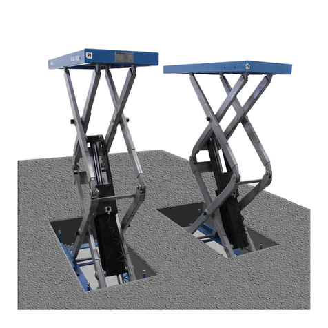
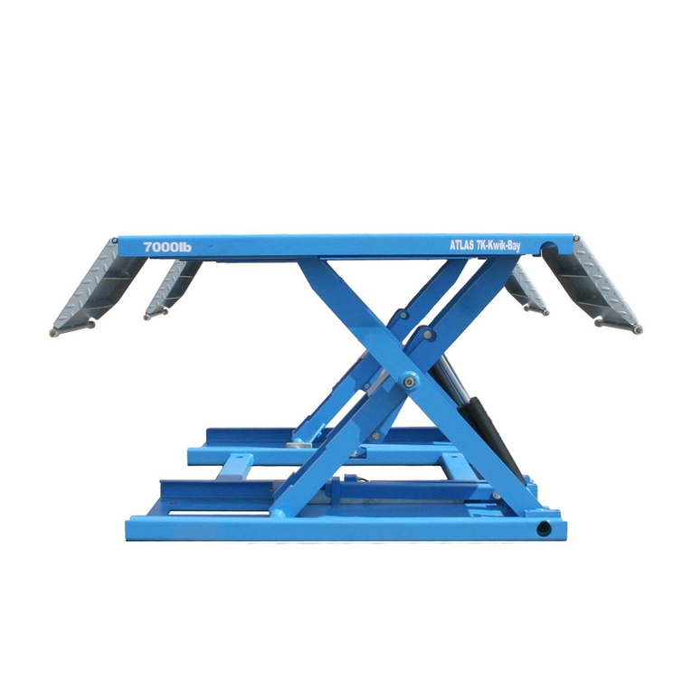
Atlas LR10 User manual

1
CONTENTS
Product Features and Specifications ........................................................... 2
Installation Requirement .............................................................................. 3
Exploded View ............................................................................................. 9
Parts List ...................................................................................................... 15

2
ĉ
PRODUCT FEATURES AND SPECIFICATIONS
LR10 Portable Low-rise Lift Features
gAutomatic safety lock :3 position safety lock .
gAutomatic safety lock release.
gPortable unit is easy to move with the power unit stand .
gHigh speed: From 0-600 mm (23-5/8
ʾ
) in just 33 seconds.
gStandard rubber pads included.
Specification
Model
Lifting
capacity
Overall
Raised
Height
Lifting Time
Overall
Length
Overall
Width
Min.Height Platform
Width
Space
Between
Platform
Gross
Weight Motor
LR10 4.5T 600mm 33s 1938m
m
1780m
m105mm 456mm 868mm 450kg 2HP/3HP
Fig.1

3
. INSTALLATION REQUIREMENT
1
ǃ
Tools Requirement
3Screw Set
3Socket Head Wrench ą
3Wrench sets˖ʿǃʿǃʿǃʿ
Fig.2
3Pliers
3Grease gun

4
2
ǃ
Power Requirement
Power source must be over 2.2kw,source cable size must be over 2.5mm² and in good condition
of contacting with floor.
III. STEPS OF INSTALLATION
A. Check the Parts Before Assembly & make sure all the parts are completed.
1ǃPackaged lift, Parts box, Power Unit and Power Unit Stand. Move aside the parts, Open the
outer packing and check the parts according to the shipment parts list.(See Fig. 3).
2ǃOpen the parts boxˈcheck the parts according to the part list (See Fig. 4).
Fig. 3
Fig.4

5
3ǃCheck the parts of the parts bag according to the parts bag list (See Fig. 5).
B.Install Hydraulic Power Unit (See Fig. 6)
Fig. 5
Fig.6

6
C. Install Connecting , Needle Valve, and Oil Hose.(See Fig.7)
Fig.7
Pay attention to the mounting of winding PTFE thread
seal tape and direction of needle valve

7
12 12
$$
$
7
7
7/
/
/
t
*
1
/
ཆ
᧕
⭥
Ⓚ
᤹䫞ᔰޣ
᤹䫞ᔰޣ
9
.0
46
/1
6%83
.0
$ $
ཆ
᧕
⭥
Ⓚ
/
1
*
t
᤹䫞ᔰޣ
D. Install Electric System
Refer to electric schenatic diagram, connect the power supply according to the
requirement of motor nameplate. Note: The lift must be good grounding and pay
attention to the direction of motor rotation when using 380V motor.
PEAK Wire connection for single phase hydraulic power unit motor (Fig.8)
1. Power supply wires (Live wire L and Zero wire N) connected with the two wires on
A.C.contactor terminal marked L1ǃL2 respectively.
2. Two wires on hydraulic power unit motor connected with A.C.contactor terminal marked
T1ǃT2 respectively.
3. A.C. contactor A2 connected with L2.
4. Two wire on button switch connected with A.C. contactor terninal marked A1ǃL1.
SPX Wire connection for single phase
hydraulic power unit motor(See Fig.9)
ˊPower supply live wire L connected with button switch wire 4ʿ.
ˊButton switch wire 3ʿconnected with motor wire 6#.
ˊMotor wire 5# connected with power supply zero wire (N).
A.C. connector
Electric schematic diagram
PEAK hydraulic power unit motor wiring
Fig.8
G
N
L
Connected with
earth wire
ƻ
6
ƻ
5
ƻ
3
ƻ
4
Spx Wire connection for single phase
hydraulic power unit motor Fig.9
P
O
W
E
R
Push button
Push button
P
O
W
E
R
Push button

8
*
᤹䫞ᔰޣ
$$
$
7
7
7
1212
/
/
/
t
/
/
/
ཆ
᧕
⭥
Ⓚ
.0
6%83
///
46
.0
9
᤹䫞ᔰޣ
$ $
Wire connection for three phase hydraulic power unit motor
1. Electric schematic diagram (See Fig.10)
2. Steps for connection (See Fig.11)
ƻ
1ǃThree Power supply wires marked (L1ǃL2ǃL3) connected with A.C.contactor terminal
marked L1ǃL2ǃL3 respectively.
ƻ
2ǃA.C. contactor terminal marked L1connected with button switch terminal marked 4#, L2
connected with A2, terminal marked A1 connected with button switch terminal marked 3#.
A1
3#
4#
L1
L2
L3
Fig.10
Connection diagram
Fig. 11
Push button
Push button

9
IV. EXPLODED VIEW
Model
˖
LR10
CYLINDER
Fig.12
Fig.13

10
Roller Assy.
Single Phase Power Unit
SPX
Single Phase
Power Unit
PEAK
Single Phase
Power Unit
Fig.14
Fig.15

11
SPX&PEAK Hydraulic power unit valve
SPX Single Phase Power Unit
(Fig.16)
PEAK Single Phase Power Unit
(Fig.17)
Release Valve
Release Valve
handle
check valve
Relif Valve
Technology
Hole
Oil outlet
Technology Hole
Return port
retaining
wire sets
Release Valve
Release Valve
handle
check valve
Relif Valve
Throttle
valve
Oil outlet
Return port
retaining
wire sets
Fig.16
Fig.17
Capacitor
Start Capacitor
Running Capacitor

12
. OPERATION INSTRUCTIONS
1. Install the oil hose between oil cylinder and power unit, connect with the power supply wire
well. The machine can be ready to use.
2. The roller assy must be disengage when lifting vehicle (See Fig.20).
3. To raise and lock the lift: Press the button up till the lift is raised to the required height and the
locks are in engaged (See Fig.18),then push release handle of the power unit, the lift would be
locked.
4. To lower lift˖Press the button UP,until the safety lock is in the released position (See Fig.19 ),
lower lift by pushing lowering handle.
5.Move lift: Pull up roller bracket, lock two roller assy to the lift with roller shaft.
(See Fig. 20 & 21 ). Moving the lift by the power unit stand.
5. Needle Valve adjustment˖
Loosen lock nut, adjust the knob in clockwise for lowering the lift slowly;Adjust the
knob in anticlockwise for lowering the lift faster. Lock the nut for suitable lowering speed.
Fig.22
)LJ )LJ
Fig.20 Fig.21
Adjust knob in clockwise Adjust knob in anticlockwise
Lock nut
Adjusted knob
Fig.22
Roller Assy. disengaged Roller Assy. engaged

13
6. There are four fixed holes in the machine, can fix the machine on ground by
3/4 X 43/4anchor bolts. See Fig.23
. MAINTENANCE SCHEDULE
Monthly:
1. Maintance all the running friction parts with grease˗Fig.24
2. Check all the joint,bolt or pin to make sure good connection.
3. Visual check if all the hydraulic holes are weared and leaking.
Every six months:
1. Visual check the posibility wared, interference and damaged of all the running parts.
2. Check and fasten if the fastener parts are loosened.
Fig.23

14
VII. TROUBLE SHOOTING
1R
Trouble
CAUSE
REMEDY
1Motor does not run
Button does not workReplace button
Wiring connections are not in
good condition or
disconnection
Repair all wiring connection
Motor burned outRepair or replace motor
AC Contactor in damage Replace AC contactor
2Motor runs but the
lift is not raised
Motor runs in reverse rotation Reverse two power wire
Release valve in damageRepair or replace
The Gear Pump in damageRepair or replace
Relief valve Valve or check
valve in damage
Repair or replace
Low oil levelFill tank
Overload or system low
preasure
Turn up the preasure of hydraulic
system
3Raising but falling
down automatic
Release valve in damageRepair or replace
Relief valve Valve or check
valve in damageRepair or replace
Cylinder or connection leaking
Replace cylinder oil seal or
connection
4Raising slowly
Oil line jamClean oil line
Insufficient power supplyCheck circuit
Air in hydraulic oilFill tank
The Gear Pump leakingReplace Gear Pump
overloadCheck the car weight
5Lift can not lower
safety lock closeOperate again
Release valve in damageReplace relif valve
Oil line system jamClean oil line

15
VIII. PARTS LIST
Item Part No. Description QTY. Note
1 630001A Platform 1
2 206019 Snap ring 19 24
3 630003 Pin for Drive-thru Ramp 19*452 2
4 630106 Bracket Pin 19*410 2
5 630107 Bracket 2
6 630108 Ramp 2
7 630109 Connecting pin for cylinder 25*92 2
8 630006 Cylinder 2
9 630007 Cylinder cover connecting pin 25*132 2
10 206032 Snap ring 25 10
11 630008 Lifting arms connecting pin 19*356 4
12 630009 Drive-in living arms 2
13 630010 Lifting arms connecting pin 19*405 4
14 630011 Supporting Lifting arms 2
15 630100 Socket Bolt M10*40 1
16 630013 Safety Lock 1
17 630014 Safety Bar 1
18 630105 Pin For Safety Bar 25*142 1
19 630012 Baseframe 1
20 640024 Roller Assy. 2
21 630102 Rubber Pad 438*1350*5 2
22 620034 Rubber Pad100*165*38 4
23 610070 Rubber Pad100*120*70 4
24 420020 Hex Bolt M10*115 2
25 630015 Compressed spring 15*12*55 2
26 209022 Washer 10 2
27 209056 Nylok Nut M10 3
28 209002 Power Unit 1
29 209003 Hex Bolt M8*25 4
30 209005 Nylok Nut M8 4
31 640021 Stand 1
32 206006 Washer 12 2
33 420046 Split Pin 3*20 2
34 630101 1/4*2650 Cylinder 1
35 630103 Transition Straight Fitting 1
36 209062 T-fitting 1
37 630104 1/4*550 Cylinder 1
38 209064 Cylinder Straight Fitting 1
39 420097 90qFitting 1
40 440011 Needle valve 1
41 440009 Power Unit Straight Fitting 1

16
LR10 Hydraulic Cylinder
Item Part No. Description QTY.
Note
Cylinder tube
Piston Rod
Silencer
Head cap
Dust ring
O - Ring
O - Ring
Piston
O-Ring
O-Ring
Y-Ring OSI
wear ring
Nut
Zerk
Roller Assy.
Item Part No. Description QTY.
Note
5ROOHUV%UDFNHW
¶Snap Ring
Connecting Shaft 
Roller Shaft 
5HGUXEEHUUROOHU
SPX Single Phase Hydraulic Power Unit
Item Part No. Description QTY.
Note
0RWRU
retaining wire sets
&RQQHFWLQJ3LQIRU0RWRU
Valve Body
5HOLHI9DOYH
:DVKHU
Socket Bolt
,QOHW3LSH
2ULQJ
)LOWHU
+H[%ROW
5HVHUYLRU
Bolt

17
ItemPart No.DescriptionQTY.
Note
Cover of Capacitor
&DSDFLWRU
5XEEHU3DG
Hex Bolt
Cover of Motor Terminal Box
6ZLWFKEXWWRQ
5HWXUQ2SHQLQJ
Oil Outlet
Release Valve
Release Valve Handle
:DVKHU
Hex Nut
Check Valve
Gear Pump
Oil Return Pipe
Filler Cap
PEAK Single Phase Hydraulic Power Unit
Item Part No. Description QTY.
Note
28A-1 209082A Motor 1
28A-2 209109 retaining wire sets 1
28A-3 209112 A.C.Connector 1
28A-4 209083A Connecting Pin for Motor 1
28A-5 209084A Valve Body 1
28A-6 209085A Relief Valve 1
28A-7 209113 Throttle Valve 1
28A-8 209086A Washer 4
28A-9 209087A Socket Bolt 4
28A-10 209088A Inlet Pipe 1
28A-11 209089A O-ring 1
28A-12 209090A Filter 1
28A-13 209091A Hex Bolt 4
28A-14 209092A Reservior 1
28A-15 209093A Cup Head Bolt and washer 4
28A-16 209094A
Cover of Capacitor 2
28A-17 209095A Start Capacitor 1
28A-17A 209095B running Capacitor 1
28A-18 209096A Rubber pad 2
28A-19 209097A Cup Head Bolt and washer 2
28A-20 209098A
Cover of Motor Terminal Box 1
28A-21 209099A
Switch Button 1
28A-22 209110A Oil Return Pipe 1

18
Item Part No. Description QTY.
Note
28A-23 209100A
Oil Outlet 1
28A-24 209105A Check Valve 1
28A-25 209101A
Release Valve 1
28A-26 209102A
Release Valve Handle 1
28A-27 209103A Washer 1
28A-28 209104A
Hex Nut 1
28A-29 209106A
Gear Pump 1
28A-30 209107A
Oil Return Pipe 1
28A-31 209108A
Filler Cap 1
Table of contents
Other Atlas Lifting System manuals
Popular Lifting System manuals by other brands

warequip
warequip P2GOUltiMate instruction manual

Atlas Equipment
Atlas Equipment BP12000X Installation & operating manual

VEVOR
VEVOR JX50 quick start guide

TECHNOLIFT
TECHNOLIFT SL-9L Installation, operation & maintenance manual

MBM
MBM LEOWORK instruction manual

AMGO Hydraulics
AMGO Hydraulics BP-12 Installation and service manual