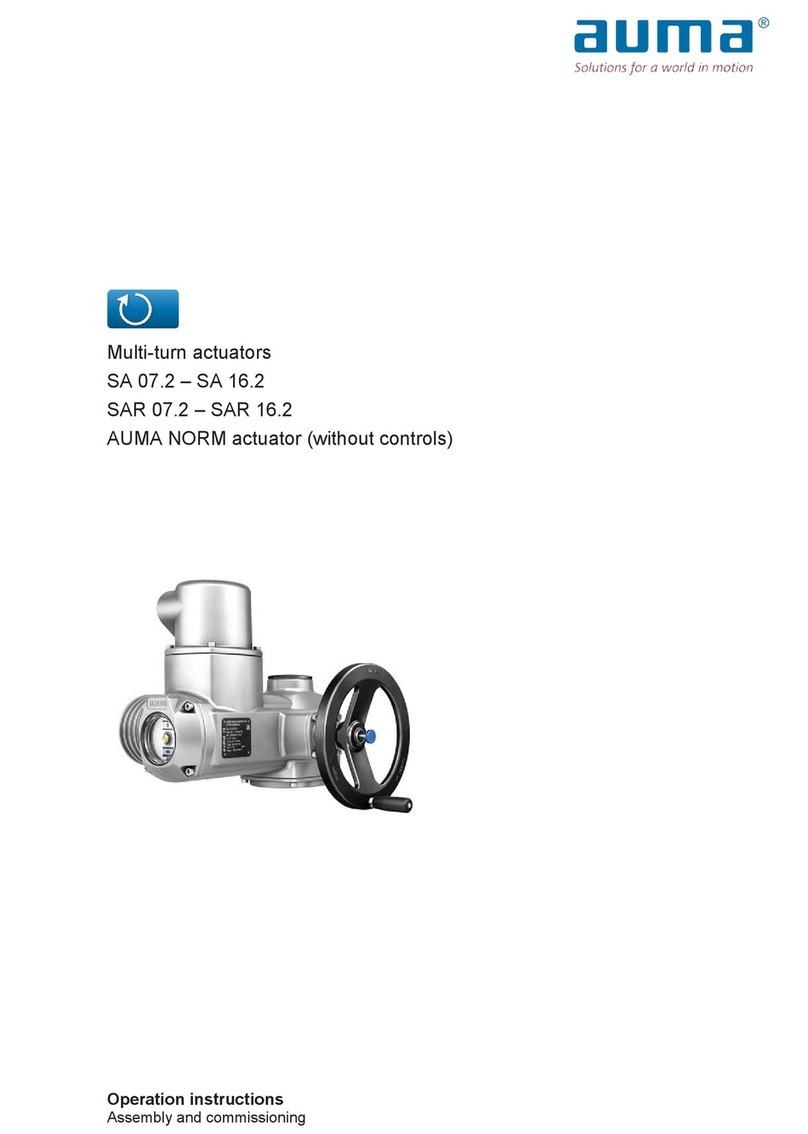
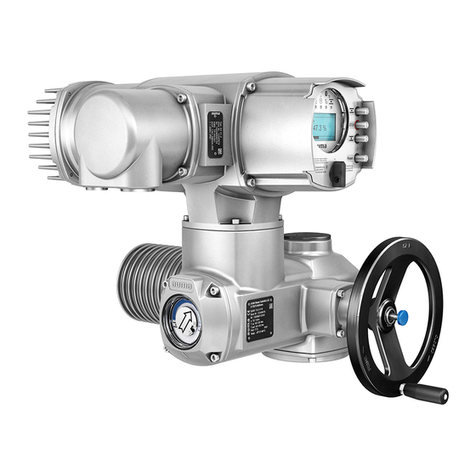
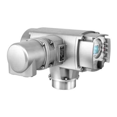
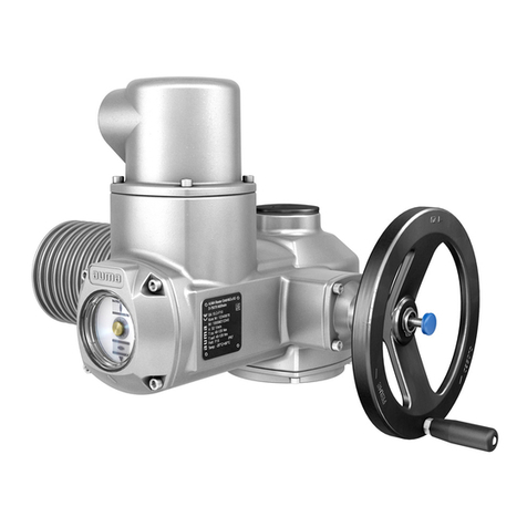
AUMA SAM Ex 07.1 User manual

Multi-turn actuators
SAM Ex 07.1 - SAM Ex 16.1
SARM Ex 07.1 - SARM Ex 16.1
AUMA MATIC Ex
Operation instructions

2
Multi-turn actuators SAM Ex 07.1 - SAM Ex 16.1 / SARM Ex 07.1 - SARM Ex 16.1
AUMA MATIC Ex Operation instructions
Scope of these instructions: These instructions are valid for explosion-proof multi-turn actuators
SA(R)M Ex 07.1 - SA(R)M Ex 16.1 with controls AUMA MATIC Ex.
These operation instructions are only valid for ”clockwise closing”, i.e. driven
shaft turns clockwise to close the valve.
Table of contents Page
1. Safety instructions . . . . . . . . . . . . . . . . . . . . . . . . . . . . . . . . . . . . . . . . . . . . . 3
1.1 Range of application . . . . . . . . . . . . . . . . . . . . . . . . . . . . . . . . . . . . . . . . . . . 3
1.2 Short description . . . . . . . . . . . . . . . . . . . . . . . . . . . . . . . . . . . . . . . . . . . . . 3
1.3 Commissioning (electrical connection) . . . . . . . . . . . . . . . . . . . . . . . . . . . . . . . . . . 3
1.4 Maintenance . . . . . . . . . . . . . . . . . . . . . . . . . . . . . . . . . . . . . . . . . . . . . . . 4
1.5 Warnings and notes. . . . . . . . . . . . . . . . . . . . . . . . . . . . . . . . . . . . . . . . . . . . 4
1.6 Further notes . . . . . . . . . . . . . . . . . . . . . . . . . . . . . . . . . . . . . . . . . . . . . . . 4
2. Technical data . . . . . . . . . . . . . . . . . . . . . . . . . . . . . . . . . . . . . . . . . . . . . . . 5
2.1 Multi-turn actuators SA(R)M Ex 07.1 -SA(R)M Ex 16.1. . . . . . . . . . . . . . . . . . . . . . . . . . 5
2.2 Controls AUMA MATIC Ex . . . . . . . . . . . . . . . . . . . . . . . . . . . . . . . . . . . . . . . . 5
3. Additional information to the legend for wiring diagrams. . . . . . . . . . . . . . . . . . . . . . . .6
4. Transport and storage . . . . . . . . . . . . . . . . . . . . . . . . . . . . . . . . . . . . . . . . . . . 7
5. Mounting to valve / gearbox . . . . . . . . . . . . . . . . . . . . . . . . . . . . . . . . . . . . . . . . 7
6. Manual operation . . . . . . . . . . . . . . . . . . . . . . . . . . . . . . . . . . . . . . . . . . . . . . 9
7. Electrical connection . . . . . . . . . . . . . . . . . . . . . . . . . . . . . . . . . . . . . . . . . . . 10
7.1 Wiring diagram. . . . . . . . . . . . . . . . . . . . . . . . . . . . . . . . . . . . . . . . . . . . . . 10
7.2 Type of seating . . . . . . . . . . . . . . . . . . . . . . . . . . . . . . . . . . . . . . . . . . . . . 10
8. Setting of limit switching: . . . . . . . . . . . . . . . . . . . . . . . . . . . . . . . . . . . . . . . . 11
8.1 Setting for end position CLOSED (black section) . . . . . . . . . . . . . . . . . . . . . . . . . . . . 11
8.2 Setting for end position OPEN (white section). . . . . . . . . . . . . . . . . . . . . . . . . . . . . . 12
9. Setting of DUO-limit switching (Option) . . . . . . . . . . . . . . . . . . . . . . . . . . . . . . . . . 12
9.1 Setting for direction CLOSE (black section) . . . . . . . . . . . . . . . . . . . . . . . . . . . . . . . 12
9.2 Settings for direction OPEN (white section) . . . . . . . . . . . . . . . . . . . . . . . . . . . . . . . 12
10. Setting of torque switching . . . . . . . . . . . . . . . . . . . . . . . . . . . . . . . . . . . . . . . 13
11. Test run . . . . . . . . . . . . . . . . . . . . . . . . . . . . . . . . . . . . . . . . . . . . . . . . . . 14
12. Setting of mechanical position indicator (option) . . . . . . . . . . . . . . . . . . . . . . . . . . . 14
13. Setting of the potentiometer (option) . . . . . . . . . . . . . . . . . . . . . . . . . . . . . . . . . . 15
14. Setting of the electronic position transmitter RWG (option). . . . . . . . . . . . . . . . . . . . . . 16
14.1 Setting for 2-wire system 4 - 20 mA and 3- /4-wire system 0 - 20 mA. . . . . . . . . . . . . . . . . . 17
14.2 Setting for 3- / 4- wire system 4 - 20 mA . . . . . . . . . . . . . . . . . . . . . . . . . . . . . . . . 18
15. Programming AUMA MATIC Ex . . . . . . . . . . . . . . . . . . . . . . . . . . . . . . . . . . . . . 19
15.1 Functions of the diagnosis LEDs on the interface board (standard version) . . . . . . . . . . . . . . 19
15.2 Programming of the logic board . . . . . . . . . . . . . . . . . . . . . . . . . . . . . . . . . . . . . 20
15.3 EMERGENCY-OPEN and EMERGENCY-CLOSE signal (option) . . . . . . . . . . . . . . . . . . . 21

1. Safety instructions
1.1 Range of application AUMA actuators are designed for the operation of industrial valves, e.g.
globe valves, gate valves, butterfly valves and ball valves.
For other applications, please consult us. AUMA is not liable for any
possible damages resulting from use in other than the designated
applications. Such risk lies entirely with the user.
Observance of these operation instructions is considered as part of the
actuator’s designated use.
1.2 Short description AUMA multi-turn actuators type SA(R)M Ex 07.1 - SA(R)M Ex 16 .1 have a
modular design. The actuators are driven by an electric motor and
controlled with the electronic controls AUMA MATIC Ex, which are included
in the scope of supply. The limitation of travel is realised via limit switches in
both end positions. Torque seating is also possible in both end positions.
The type of seating is stated by the valve manufacturer.
1.3 Commissioning
(electrical connection)
For work carried out in hazardous areas, special regulations (European
standard EN 60079-17) must be observed.
Work at the open actuator under voltage must only be performed if it is
assured that for the duration of the work there is no danger of explosion.
Pay attention to national regulations.
During electrical operation certain parts inevitably carry lethal voltages.
Work on the electrical system or equipment must only be carried out by a
skilled electrician himself or by specially instructed personnel under the
control and supervision of such an electrician and in accordance with the
applicable electrical engineering rules.
3
Multi-turn actuators SAM Ex 07.1 - SAM Ex 16.1 / SARM Ex 07.1 - SARM Ex 16.1
Operation instructions AUMA MATIC Ex
Page
16. Electronic positioner (option) . . . . . . . . . . . . . . . . . . . . . . . . . . . . . . . . . . . . . . 21
16.1 Technical data . . . . . . . . . . . . . . . . . . . . . . . . . . . . . . . . . . . . . . . . . . . . . . 21
16.2 Setting . . . . . . . . . . . . . . . . . . . . . . . . . . . . . . . . . . . . . . . . . . . . . . . . . . 21
16.3 Positioner adjustment end position CLOSED (standard version) . . . . . . . . . . . . . . . . . . . . 23
16.4 Positioner adjustment end position OPEN (standard version). . . . . . . . . . . . . . . . . . . . . . 24
16.5 Setting of the sensitivity . . . . . . . . . . . . . . . . . . . . . . . . . . . . . . . . . . . . . . . . . 25
16.6 Positioner adjustment end position OPEN (inverse operation) . . . . . . . . . . . . . . . . . . . . . 25
16.7 Positioner adjustment end position CLOSED (inverse operation). . . . . . . . . . . . . . . . . . . . 26
16.8 Positioner in Split Range version (option) . . . . . . . . . . . . . . . . . . . . . . . . . . . . . . . . 27
16.8.1 Split Range: description of functions . . . . . . . . . . . . . . . . . . . . . . . . . . . . . . . . . . 27
16.8.2 Programming . . . . . . . . . . . . . . . . . . . . . . . . . . . . . . . . . . . . . . . . . . . . . . 27
16.8.3 Positioner adjustment for Split Range . . . . . . . . . . . . . . . . . . . . . . . . . . . . . . . . . . 27
17. Timer (option) . . . . . . . . . . . . . . . . . . . . . . . . . . . . . . . . . . . . . . . . . . . . . . . 28
17.1 Function of the diagnosis LEDs (timer) . . . . . . . . . . . . . . . . . . . . . . . . . . . . . . . . . 28
17.2 Setting of the timer. . . . . . . . . . . . . . . . . . . . . . . . . . . . . . . . . . . . . . . . . . . . 29
18. Fuses . . . . . . . . . . . . . . . . . . . . . . . . . . . . . . . . . . . . . . . . . . . . . . . . . . . 29
19. Maintenance . . . . . . . . . . . . . . . . . . . . . . . . . . . . . . . . . . . . . . . . . . . . . . . . 30
20. Declaration of conformity and declaration of incorporation . . . . . . . . . . . . . . . . . . . . . . 31
21. PTB-Certificate of Conformity . . . . . . . . . . . . . . . . . . . . . . . . . . . . . . . . . . . . . . 32
Index . . . . . . . . . . . . . . . . . . . . . . . . . . . . . . . . . . . . . . . . . . . . . . . . . . . . 34
Addresses of AUMA offices and representatives. . . . . . . . . . . . . . . . . . . . . . . . . . . . 35

1.4 Maintenance The maintenance instructions (refer to page 30) must be observed,
otherwise a safe operation of the actuator is no longer guaranteed.
1.5 Warnings and notes Non-observance of the warnings and notes may lead to serious injuries or
damages. Qualified personnel must be thoroughly familiar with all warnings
and notes in these operation instructions.
Correct transport, proper storage, mounting and installation, as well as
careful commissioning are essential to ensure a trouble-free and safe
operation.
The following references draw special attention to safety-relevant
procedures in these operation instructions. Each is marked by the
appropriate pictograph.
This pictograph means: Note!
”Note” marks activities or procedures which have major influence on the
correct operation. Non-observance of these notes may lead to
consequential damage.
This pictograph means: Electrostatically endangered parts (ESD)!
If this pictograph is attached to a printed circuit board, it contains parts
which may be damaged or destroyed by electrostatic discharges. If the
boards need to be touched during setting, measurement or for exchange, it
must be assured that immediately before a discharge through contact with
an earthed metallic surface (e.g. the housing) has taken place.
This pictograph means: Warning!
”Warning” marks activities or procedures which, if not carried out correctly,
can affect the safety of persons or material.
1.6 Further notes This pictograph means: Procedure may have been performed by
valve manufacturer !
If actuators are delivered mounted to a valve, this step has been done in the
valve manufacturer’s plant.
Setting must be checked during commissioning!
4
Multi-turn actuators SAM Ex 07.1 - SAM Ex 16.1 / SARM Ex 07.1 - SARM Ex 16.1
AUMA MATIC Ex Operation instructions
MOV
M

2. Technical data
2.1 Multi-turn actuators SA(R)M Ex 07.1 -SA(R)M Ex 16.1
2.2 Controls AUMA MATIC Ex
5
Multi-turn actuators SAM Ex 07.1 - SAM Ex 16.1 / SARM Ex 07.1 - SARM Ex 16.1
Operation instructions AUMA MATIC Ex
Explosion protection:
(according to EN 50 014, 50 018, 50 19) EEx de IIB T4
Types of duty: SAM Ex:
(acc. to IEC 34-1/ VDE 0530) SARM Ex:
Standard: Short-time duty S2 - 15 min
Standard: Intermittent duty S4 - 25 % ED. Permissible number of starts
refer to Technical data sheet for SAR Ex / name plate
Limit switching: Counter gear mechanism for end positions CLOSED / OPEN
Torque switching: Adjustable torque switching for closing and opening direction
Speeds: Refer to Technical data sheets for SA Ex and SAR Ex
Heater in switch compartment: Approx. 5 W, 24 V, internally supplied
Motor: 3-phase AC motor.
Motor protection: 3 PTC-thermistors and tripping device with reset possibility via selector switch
at local controls
Electrical connection: Terminals
Wiring diagram: Refer to name plate on AUMA MATIC Ex
Ambient temperature: Standard: −20 °C to +40 °C
Option: −20 °C to +60 °C (special sizing)
Enclosure protection:
(according to 60 529): Standard: IP 67
Option: IP 68
Explosion protection:
(according to EN 50 014, 50 018, 50 019) EEx d IIB T4
Types of protection: Motor and switch compartment: EEx d
Terminal compartment: EEx e(optional EEx d)
Corrosion protection: Standard: KN
Option: KS, KX
Integral controls AUMA MATIC Ex, type AM Ex 01.1 and AM Ex 02.1
Explosion protection: See multi-turn actuator
Voltage supply Refer to name plate
Motor controls Reversing contactors Mechanical, electrical, electronically interlocked, max. 690 V AC, max. 7,5 kW
External control voltage Standard: 24V DC, (galvanically isolated from internal voltage supply)
Binary inputs (input signals)
Galvanic isolation
Nominal voltage
Current input
Standard: OPEN-STOP-CLOSE
Option: Switch-over AUTOMATIC-MANUAL1) for input signals OPEN-CLOSE
Opto-isolators
24 V DC, from internal power supply (max. 50 mA load) or from external source
10 - 15 mA per input
Analogue inputs (option) See positioner
Relay outputs –Collective fault signal:
Phase failure/ motor protection tripped/ torque fault: Torque switch operated
in mid-travel (can be separated, see table 3, page 20)
–4 signal relays:
End position OPEN / End position CLOSED / selector switch LOCAL /
selector switch REMOTE
Monitor relay (diagnosis LEDs) –Phase failure, motor protection tripped
–Torque fault: Torque switch operated in mid-travel
Analogue output (Option) Position actual value (galvanically isolated) E2 = 0/4 - 20 mA
Positioner (Option) –Input range (position nominal value) E1 = 0/4 - 20 mA
Input resistance 250 Ohm
–Feedback E2 (position actual value): 0/4 - 20 mA
Emergency operation (EMERGENCY)
(option) Effective in all 3 selector switch positions LOCAL, OFF and REMOTE (see page 21):
–End position OPEN
–End position CLOSED
Timer (option) Parameters Running time/ off time independently adjustable (1-30 seconds)
Local controls Standard: Selector switch LOCAL-OFF-REMOTE, reset motor protection,
lockable
Push-buttons OPEN-STOP-CLOSE
Option: Indication lights for end position OPEN, FAULT, end position
CLOSED
Enclosure protection Standard: IP 67
Option: IP 68
Temperature
range Standard: −20 °C to + 40 °C
Option: −20 °C to + 60 °C (special sizing)
Electrical connection see clause 7, page 10
1) Only in conjunction with the positioner

3. Additional information to the legend for wiring diagrams
Information A: A running indication is possible with blinker transmitter (S5) installed
(opening and closing of contacts)
Direction CLOSE: Connections XK6 - XK7
Direction OPEN: Connections XK6 - XK8
The contacts remain closed in the end positions.
When connected to an external PLC the blinking signal can be switched off
via the DIP-switches (table 3, page 20).
Information B: The type of seating in the end positions is determined by the valve
manufacturer. Setting is possible at the programming switches S1-2 and
S3-2 (see subclause 15.2, page 20). The tripping of a torque switch in an
intermediate position switches off the actuator and gives a fault signal.
The limit switches serve for signalisation when switching off by torque
seating. They need to be set so that the appropriate switch is tripped shortly
before reaching the end position. If the torque switch trips before the limit
switch, the actuator is switched off and a fault signal is given.
For further programming possibilities, e.g. self-retaining in operation mode
REMOTE, see table 3, page 20.
Information D: The following faults are registered and can be transmitted to the control
room as a potential-free collective fault signal:
- Power failure
- Phase failure
- Motor protection tripped
- Torque switch tripped in mid-travel.
This signal can be switched off in the programming, refer to table 3,
page 20.
Information E: Input signals according to DIN 19 240.
The nominal current of the inputs XK2; XK3 and XK4 is 10-15 mA. If internal
voltage 24 V DC is used for remote control, it must only be connected via
potential-free contacts.
Information F: In case of wrong phase sequence the rotating field is automatically
corrected. In case of a phase failure the actuator stops. This fault is
indicated at LED V14 on the interface board. For collective fault signal see
information D.
Information G: Potential-free contacts are available for signals. The internal control voltage
(XK11 / + 24 V and XK5 / - 24V) must not be used for external lamps,
relays etc.
6
Multi-turn actuators SAM Ex 07.1 - SAM Ex 16.1 / SARM Ex 07.1 - SARM Ex 16.1
AUMA MATIC Ex Operation instructions

4. Transport and storage
.
Transport to place of installation in sturdy packing.
.
Do not attach ropes or hooks to the handwheel for the purpose of lifting
by hoist.
.
if multi-turn actuator is mounted on valve, attach ropes or hooks for the
purpose of lifting by hoist to valve and not to multi-turn actuator.
.
Store in well-ventilated, dry room.
.
Protect against floor dampness by storage on a shelf or on a wooden
pallet.
.
Cover to protect against dust and dirt.
.
Apply suitable corrosion protection agent to bright surfaces.
If multi-turn actuators are to be stored for a long time (more than 6 months),
the following points must be observed additionally:
.
Prior to storage: Protect bright surfaces, in particular the output drive
parts and mounting surface, with long-term corrosion protection agent.
.
Check for corrosion approximately every 6 months. If first signs of
corrosion show, apply new corrosion protection.
After mounting, connect actuator immediately to electrical system, so that
condensation is prevented by the heater.
5. Mounting to valve / gearbox
.
Prior to mounting the multi-turn actuator must be checked
for any damage.
.
Damaged parts must be replaced by original spare parts.
Mounting is most easily done with the valve shaft / gearbox shaft pointing
vertically upward. But mounting is also possible in any other position.
The multi-turn actuator leaves the factory in position CLOSED (limit switch
CLOSED tripped).
.
Check if mounting flange fits the valve/gearbox.
Spigot at flanges should be loose fit!
The output drive types B1, B2, B3 or B4 (figure A) are delivered with bore
and keyway (usually according to ISO 5210).
7
Multi-turn actuators SAM Ex 07.1 - SAM Ex 16.1 / SARM Ex 07.1 - SARM Ex 16.1
Operation instructions AUMA MATIC Ex
MOV
M
O
utput drive type B 1
/
B2
plug sleeve
O
utput drive type B 3
/
B4
bore with keyway
Figure A

For output drive type A (figure B), thread must match the thread of the valve
stem. If not ordered explicitly with thread, the stem nut is unbored or with
pilot bore when delivered. Finish machining of stem nut see below.
.
Check whether bore and keyway match the input shaft of valve/gearbox.
.
Thoroughly degrease mounting faces of multi-turn actuator and valve /
gearbox.
.
Apply a small quantity of grease to input shaft of valve / gearbox.
.
Place actuator on valve / gearbox and fasten with bolts (at least quality
8.8, refer to table 1) evenly crosswise.
Finish machining of stem nut (output drive type A):
The output drive flange does not have to be removed from the actuator.
.
Remove spigot ring (80.2, figure B) with the help of a wrench or similar
tool from the mounting flange.
.
Take off stem nut (80.3) together with thrust bearing (80.01) and thrust
bearing races (80.02).
.
Remove thrust bearing and thrust bearing races from stem nut.
.
Drill and bore stem nut and cut thread
When fixing in the chuck, make sure stem nut runs true!
.
Clean the machined stem nut.
.
Apply ball bearing grease to thrust bearing and races, then place them on
stem nut.
.
Re-insert stem nut with thrust bearings into the mounting flange. Ensure
that dogs are placed correctly in the slots of the hollow shaft.
.
Screw in spigot ring until it is firm against the shoulder.
.
Press a few squirts of grease into the grease nipple with a grease gun.
Protection tube for rising valve stem
.
Protection tubes may be supplied loose. Wrap thread with hemp or Teflon
tape.
.
Screw protection tube into thread and tighten it firmly.
.
For corrosion protection KS/ KX, push down the seal to the housing.
.
Touch up possible defects in painting.
.
Check, wether sealing cap is available and without damage.
8
Multi-turn actuators SAM Ex 07.1 - SAM Ex 16.1 / SARM Ex 07.1 - SARM Ex 16.1
AUMA MATIC Ex Operation instructions
80.3
80.2
80.01/ 80.02
O
utput drive type A
stem nut
Figure B
8.8 TA(Nm)
M 6 10
M 8 25
M 10 50
M 12 87
M 16 220
Table 1

6. Manual operation Manual operation should only be engaged when motor is
not running. Switching over while motor is running may lead
to damage at multi-turn actuator (figure C)!
.
Lift change-over lever in the center of the handwheel up to max. 85°,
while slightly turning the handwheel back and forth until manual drive
engages (figure D).
Manual force is sufficient for operating the change-over
lever. The use of an extension is neither necessary nor
permitted. Excessive force may damage the change-over
mechanism.
.
Release change-over lever (should snap back into initial position by
spring action). If change-over lever does not snap back, assist with hand
to assure that the lever comes to the initial position
(figure E).
.
Manual operation remains engaged until motor is started again. Then
motor operation is engaged automatically.
.
Turn handwheel into desired direction (figure F).
Only operate manually when change-over lever is in its
initial position!
.
Manual operation is automatically disengaged when motor is started
9
Multi-turn actuators SAM Ex 07.1 - SAM Ex 16.1 / SARM Ex 07.1 - SARM Ex 16.1
Operation instructions AUMA MATIC Ex
Figure DFigure C
Figure E Figure F

Plug cover
Contact conduit
Switch compartment
cover
AUMA MATIC Ex
Name plate AUMA MATI
C
Ex
Name plate multi-turn actuator
Actuator
SA/ SAR
7. Electrical connection When working in potentially explosive areas, observe the
standard EN 60079-17 ”Inspection and Maintenance of
Electrical Installations in Hazardous Areas”.
Work on the electrical system or equipment must only be
carried out by a skilled electrician himself or
by specially instructed personnel under the control and
supervision of such an electrician and in accordance with
the applicable electrical engineering rules.
AUMA actuators SA(R)M Ex are operated by the electronic con-
trols AUMA MATIC Ex. These controls are mounted to the actua-
tor and form one unit together with the switch compartment of the
actuator. This unit is designed as a flameproof enclosure ”EEx d”
(see Techn. data, page 5).
The electrical connection to the power supply is made at a
plug/socket connector with terminal connection as standard. It is
designed for explosion protection ”EEx e” (increased safety) and
separated from the flameproof compartment by flameproof con-
tact conduits. A plug/socket connector is situated in the
flameproof compartment, which makes an easy separation from
the mains possible.
Before pulling the plug/socket connec-
tor, disconnect actuator from the mains.
.
Check whether type of current, supply voltage and
frequency correspond to motor data (refer to
name plate at motor and AUMA MATIC Ex).
.
Remove plug cover (figure G).
.
Insert cable glands with ”EEx e”-approval and of size
suitable for connecting cables.
.
Enclosure protection IP 67 or IP 68 is only ensured if
suitable cable glands are used.
Cross sections: control cables max. 1,5 mm2, power cables max. 6 mm2.
.
Remove cable sheating in a length of 120 - 140 mm.
.
Strip wires: controls max. 8 mm, motor max. 12 mm
.
For flexible cables use wire end sleeves according to DIN 46228
7.1 Wiring diagram
.
Connect cables according to order related wiring diagram MSP. . . KMS
TP . . .. The wiring diagram applicable to the actuator is attached to the
handwheel in a weather-proof bag, together with the operation
instructions. In case the wiring diagram is not available, it can be obtained
from AUMA (state commission no., refer to name plate) or downloaded
directly from the internet (see page 34).
Additional notes to the references mentioned in the wiring diagram,
e.g. >Information A< see clause 3, page 6
.
Heater for prevention of condensation is internally supplied, unless
ordered differently.
.
Only the same potential can be switched on the two circuits of the
switches. Different potentials require tandem switches.
Switches with gold plated contacts (option) may only be loaded with low
voltage (< 50 V DC / 400 mA).
.
For the connection of position transmitters (potentiometers, RWG)
screened cables must be used
7.2 Type of seating
.
The valve manufacturer specifies whether switching off in the end
positions should be by limit switch (limit seating) or torque switch (torque
seating). In case type of seating is to be changed, see programming
AUMA MATIC Ex, subclause 15.2, page 20.
.
Clean sealing faces at cover and check whether O-ring is o.k. Apply a thin
film of non-acidic grease (e.g. Vaseline) to the sealing faces.
10
Multi-turn actuators SAM Ex 07.1 - SAM Ex 16.1 / SARM Ex 07.1 - SARM Ex 16.1
AUMA MATIC Ex Operation instructions
Figure G
MOV
M

.
Replace cover and fasten 4 bolts evenly crosswise
.
Fasten cable glands firmly to ensure appropriate enclosure protection.
8. Setting of the limit switching:
These operation instructions are only valid for ”clockwise closing”, i.e. driven
shaft turns clockwise to close the valve.
.
Engage manual operation as described under clause 6
on page 9.
Ensure that actuator is not connected to
the mains.
.
Remove switch compartment cover and, if provided, pull
off indicator disc (figure H1). Open end spanner (ca. 10
mm) may be used as lever.
8.1 Setting for end position CLOSED (black section)
.
Turn handwheel clockwise until valve is closed.
.
Press down and turn setting spindle A (figure H2) with screw driver (5
mm) in direction of arrow, thereby observe pointer B. While a ratchet is
felt and heard, the pointer B moves 90° every time.
When pointer B is 90° from mark C, continue turning slowly. When pointer
B has reached the mark C, stop turning and release setting spindle.
In case of having turned too far, continue turning and approach
mark C anew.
11
Multi-turn actuators SAM Ex 07.1 - SAM Ex 16.1 / SARM Ex 07.1 - SARM Ex 16.1
Operation instructions AUMA MATIC Ex
Mark
Cove
r
Indicator disc (Option)
Figure H1
MOV
M
D
F
Figure H2

8.2 Setting for end position OPEN (white section)
.
Turn handwheel counter-clockwise until valve is open, then turn back
approximately 1/2 a turn.
.
Press down and turn setting spindle D (figure H3) with screw driver (5
mm) in direction of arrow, thereby observe pointer E. While a ratchet is felt
and heard, the pointer E moves 90° every time.
When pointer E is 90° from mark F, continue turning slowly. When pointer
E has reached the mark F, stop turning and release setting spindle.
In case of having turned too far, continue turning and approach mark F
anew.
Red test buttons T and P (figure H2, page 11) serve for operating the
microswitches of torque and limit switching.
9. Setting of the DUO-limit switching (option)
For setting, the switching point (intermediate position) must
be approached from the same direction as afterwards in
electrical operation.
Any application can be switched on or off via the two intermedia-
te position switches.The switch-on / switch-off function is realised
by connecting of the appropriate NC and NO contacts.
.
Move valve to desired intermediate position.
9.1 Setting for direction CLOSE (black section)
.
Turn setting spindle G (figure H3) with screw driver (5 mm) in direction of
arrow, thereby observe pointer H. While a ratchet is felt and heard, the
pointer H moves 90° every time.
When pointer H is 90° from mark C, continue turning slowly. When pointer
H has reached the mark C, stop turning and release setting spindle.
In case of having turned too far, continue turning and approach mark C
anew.
9.2 Settings for direction OPEN (white section)
.
Turn setting spindle K (figure H3) with screw driver (5 mm) in direction of
arrow, thereby observe pointer L. While a ratchet is felt and heard, the
pointer L moves 90° every time.
When pointer L is 90° from mark F, continue turning slowly. When pointer
L has reached the mark F, stop turning and release setting spindle. In
case of having turned too far, continue turning and approach mark F
anew.
12
Multi-turn actuators SAM Ex 07.1 - SAM Ex 16.1 / SARM Ex 07.1 - SARM Ex 16.1
AUMA MATIC Ex Operation instructions
MOV
M
MOV
M

10. Setting of the torque switching
.
Set torque must suit the valve!
.
When multi-turn actuator is delivered by a valve
manufacturer, setting was made during testing.
.
This setting should only be changed with the consent of
the valve manufacturer!
.
Loosen both lock screws O at the torque dial (figure J).
.
Turn torque dial P to set it to the required torque (1 da Nm = 10 Nm).
Example:
Figure J shows the following setting:
3,5 da Nm = 35 Nm for direction CLOSE
3,5 da Nm = 35 Nm for direction OPEN
.
Tighten lock screws O again
.
The torque switches can also be operated in manual
operation. With corresponding electrical controls, the
tripping of a torque switch is stored and thus a re-starting
in a specific direction prevented.
.
The torque switching acts as overload protection over full
travel, also when stopping in the end positions by limit
switch.
.
If applicable, press indicator disc on shaft and perform setting as
described under clause 12, page 14.
.
Clean sealing faces at cover and housing; check whether O-ring is in
good condition. Apply a thin film of non-acidic grease to the sealing faces.
.
Replace cover on switch compartment and fasten bolts evenly crosswise.
13
Multi-turn actuators SAM Ex 07.1 - SAM Ex 16.1 / SARM Ex 07.1 - SARM Ex 16.1
Operation instructions AUMA MATIC Ex
*) Option
Figure H3
MOV
M
P
O
OP
Setting CLOSED
S
etting
O
PEN
Figure J

11. Test run Work at the open actuator under voltage must only be
performed if it is assured that for the duration of the work
there is no danger of explosion.
.
Set selector switch to position OFF (0) (figure K).
.
Switch on the mains voltage.
.
Engage manual operation as described under clause 6 on page 9.
.
Move actuator manually into both end positions of the valve.
.
Check whether limit switching is set correctly. Hereby observe that the
appropriate switch is tripped in each end position and released again after
the direction of rotation is changed. If this is not the case, the limit
switching must first be set, as described under clause 11 on page 8.
When limit switching is set correctly:
.
Perform test run at local controls with selector switch in position Local (I)
via push-buttons (figure K).
Red test buttons T and P (figure M, page 15) serve for operating the
microswitches of torque and limit switching.
The current input is not interrupted in position OFF.
12. Setting of mechanical position indicator (option)
Indicator disc rotates approximately 180° at full travel from OPEN to CLOSE
or vice versa.
A suitable reduction gearing was installed in our works. If the turns per
stroke are changed at a later date, the reduction gearing may have to be
exchanged, too.
.
Move valve to end position CLOSED.
.
Turn lower indicator disc until symbol CLOSED is in alignment with the
mark on the cover (figure L).
.
Move actuator to end position OPEN.
.
Hold lower indicator disc in position and turn upper disc with
symbol OPEN until it is in alignment with the mark at the cover.
14
Multi-turn actuators SAM Ex 07.1 - SAM Ex 16.1 / SARM Ex 07.1 - SARM Ex 16.1
AUMA MATIC Ex Operation instructions
Indication lights
(
o
OPEN
Fault
CLOSED
ption
)
:
Push-buttons
OPEN
STOP
CLOSE
Selector switch position
0: OFF
: Operation by local controls
: Operation by remote controls
: Reset motor protection
I
II
III
Figure K: Local controls
MOV
M

13. Setting of the potentiometer (option)
.
Move valve to end position CLOSED.
.
Remove switch compartment cover and, if provided, pull off indicator disc
as described under clause 8, page 11.
.
Turn potentiometer (R2) clockwise to initial position.
End position CLOSED corresponds to 0 %, end position OPEN to 100 %.
Due to the ratio of the reduction gearings for the position
transmitter the complete resistance range is not always
utilized for the whole travel. Therefore an external possibility
for adjustment (setting potentiometer) must be provided.
.
Perform fine-tuning of the zero point at external setting potentiometer.
.
If applicable, press indicator disc on shaft and perform setting as
described under clause 12.
.
Clean sealing face, check O-Ring, apply a thin film of non-acidic grease to
sealing face.
.
Fit and fasten switch compartment cover.
15
Multi-turn actuators SAM Ex 07.1 - SAM Ex 16.1 / SARM Ex 07.1 - SARM Ex 16.1
Operation instructions AUMA MATIC Ex
Mark
Cove
r
Indicator disc
Figure L
DOL
WOL
WDL
WSR
DSR
WDR
Cover
plate
R2
P
T
Figure M

14. Setting of the electronic position transmitter RWG (option)
– For a remote indication or external control –
The electronic position transmitter is set in the factory according to the
signal range stated in the purchase order. Perform a subsequent
adjustment according to subclauses 14.1 or 14.2.
After mounting the actuator to the valve, check the setting by measuring the
output current at the designated measuring points (see subclause 14.1 or
14.2) and re-adjust, if necessary.
For inverse operation interchange the connections 7 (red/RD) and 5
(black/BK) at position transmitter board (figure N).
16
Multi-turn actuators SAM Ex 07.1 - SAM Ex 16.1 / SARM Ex 07.1 - SARM Ex 16.1
AUMA MATIC Ex Operation instructions
Technical
data RWG 4020
Wiring
diagrams
MSP... KMS TP . . 4 / . . .
(requires 2 external wires)
3-/ 4-wire system
MSP... KMS TP . 4 . / . . .
MSP... KMS TP . 5 . / . . .
2-wire system
Output current I 0 - 20 mA, 4 - 20 mA 4 - 20 mA
Supply
voltage Uv
internal supply
24 V DC
external supply
14 V DC + (I x RB),
max. 30 V
Max. input
current
I 24 mA at 20 mA
output current
20 mA
Max. load RB600 Ω(Uv - 14 V) / 20 mA
Table 2
Measuring
point 1
+
3- and 4- wire system
R2N M
max
(20 mA)
(0/4 mA)
2- wire system
For change-over wiring also needs to be changed
0/4 - 20 mA
Measuring-
point 2
-
Figure N: Position transmitter board

14.1 Setting for 2-wire system 4 - 20 mA and 3- /4-wire system 0 - 20 mA
.
Connect voltage to MATIC Ex.
.
Move valve to end position CLOSED.
.
Remove switch compartment cover (observe safety note on
page 10) and, if provided, pull off indicator disc as described
under clause 8, page 11.
.
For actuators with measuring points not accessible, remove
cover plate (figure O1).
.
Connect ammeter for 0 - 20 mA to measuring points (figure N,
page 16 or figure O1).
In end position CLOSED of 3- or 4-wire system, the value
after setting must be 0 mA, for 2-wire system it must be 4 mA.
The circuit (external load) must be connected (observe
max. external load RB), or the appropriate poles at the
connecting terminals must be linked (refer to wiring
diagram MSP...KMS TP...), otherwise no value can be
measured.
.
Turn potentiometer (R2) clockwise to initial position.
Turn potentiometer (R2) whilst decreasing output signal until stop is felt.
.
Turn trimmer potentiometer (N) clockwise, until output current starts to
increase.
.
Turn back trimmer potentiometer (N), until a residual current of
approx. 0,1 mA (or 4,1 mA in case of 2-wire system) is reached. This
ensures that the signal remains above the dead and live zero point.
.
Move valve to end position OPEN.
.
Set to end value 20 mA with trimmer potentiometer (M).
.
Approach end position CLOSED anew and check minimum value (0 mA
or 4 mA). If necessary, correct the setting.
.
In case cover plate (figure O1) has been removed, fit it again.
.
If applicable, press indicator disc on shaft and perform setting as
described under clause 12, page 14.
.
Clean sealing face, check O-Ring, apply a thin film of non-acidic grease to
sealing face.
.
Fit and fasten switch compartment cover.
If the maximum value can not be reached, the selection of
the reduction gearing must be checked.
17
Multi-turn actuators SAM Ex 07.1 - SAM Ex 16.1 / SARM Ex 07.1 - SARM Ex 16.1
Operation instructions AUMA MATIC Ex
Cover plate
Measuring
point 2 (–)
0/4 - 20 mA
Measuring
point 1 (+)
0/4 - 20 mA
R2
N (0
/
4mA) M(20mA)
Figure O1

14.2 Setting for 3- / 4- wire system 4 - 20 mA
.
Connect voltage to MATIC Ex.
.
Move valve to end position CLOSED.
.
Remove switch compartment cover (observe safety note on
page 10) and, if provided, pull off indicator disc as described
under clause 8, page 11.
.
For actuators with measuring points not accessible, remove
cover plate (figure O2).
.
Connect ammeter for 0 - 20 mA to measuring points (figure N,
page 16 or figure O2).
The circuit (external load) must be connected (observe
max. external load RB), or the appropriate terminals at the
electrical connection must be linked (refer to wiring
diagram MSP...KMS TP...), otherwise no value can be
measured.
.
Turn potentiometer (R2) clockwise to initial position.
Turn potentiometer (R2) whilst decreasing output signal until stop is felt.
.
Turn trimmer potentiometer (N) clockwise, until output current starts to
increase.
.
Turn back potentiometer (N), until a rest current of approx. 0,1 mA
is reached.
.
Move valve to end position OPEN.
.
Set to end value 16 mA with trimmer potentiometer (M).
.
Move valve to end position CLOSED.
.
Set potentiometer (N) from 0,1 mA to initial value 4 mA.
This results in a simultaneous shift of the end value by 4 mA, so that the
range is now 4 - 20 mA.
.
Approach both end positions anew and check setting. If necessary,
correct the setting.
.
In case cover plate (figure O2) has been removed, fit it again.
.
If applicable, press indicator disc on shaft and perform setting as
described under clause 12, page 14.
.
Clean sealing face, check O-Ring, apply a thin film of non-acidic grease to
sealing face.
.
Fit and fasten switch compartment cover.
If the maximum value can not be reached, the selection of
the reduction gearing must be checked.
18
Multi-turn actuators SAM Ex 07.1 - SAM Ex 16.1 / SARM Ex 07.1 - SARM Ex 16.1
AUMA MATIC Ex Operation instructions
Cover plate
Measuring
point 2 (–)
0/4 - 20 mA
Measuring
point 1 (+)
0/4 - 20 mA
R2
N (0
/
4mA) M(20mA)
Figure O2

15. Programming AUMA MATIC Ex
During all work at the AUMA MATIC Ex observe:
Work at the open actuator under voltage must only be
performed if it is assured that for the duration of the work
there is no danger of explosion.
15.1 Functions of the diagnosis LEDs on the interface board (standard version)
V14 is illuminated: Phase failure and/or motor protection tripped,
reset by selector switch position III at local
controls
V15 is illuminated: Torque fault: Torque switch operated in
mid-travel
LEDs STOP, CLOSE, OPEN
indicate available remote control commands.
19
Multi-turn actuators SAM Ex 07.1 - SAM Ex 16.1 / SARM Ex 07.1 - SARM Ex 16.1
Operation instructions AUMA MATIC Ex
Logic board
Electrical connection
Power supply unit
Reversing contactors
Signal and control board
Interface board
Cover plate
Local controls
Plug/socket connector
to actuator
Figure P: AUMA MATIC Ex standard version
Figure Q1: Cover plate above interface board

15.2 Programming of the logic board
The type of seating - limit or torque seating (switch S1-2 and switch S3-2,
figure Q2) must be determined by the valve manufacturer.
.
Set desired programming according to table 3 at the switch S2-2.
20
Multi-turn actuators SAM Ex 07.1 - SAM Ex 16.1 / SARM Ex 07.1 - SARM Ex 16.1
AUMA MATIC Ex Operation instructions
MOV
M
S3-2
S2-2
S1-2 limit seating
in end position
CLOSED
Position 1:
S1-2
Position 2:
torque seating
in end position
CLOSED
S1-2
limit seating
in end position
OPEN
Position 1:
S3-2
Position 2:
torque seating
in end position
OPEN
S3-2
(OPEN)
(CLOSED)
Figure Q2: Logic board A2
DIP switch S2-2 Programming
(ON = pushed down)
Direction CLOSE Direction OPEN
Self-retaining REMOTE
Push-to-run operation REMOTE
Self-retaining LOCAL
Push-to-run operation LOCAL
activated deactivated
Blinker transmitter
included not included
Torque switch operated in mid-
travel within collective fault signal
Table 3
ON 123456
OFF ON 123456
OFF
ON 123456
OFF ON 123456
OFF
ON 123456
OFF ON 123456
OFF
ON 123456
OFF ON 123456
OFF
ON 123456
OFF ON 123456
OFF
ON 123456
OFF ON 123456
OFF
This manual suits for next models
6
Table of contents
Other AUMA Controllers manuals

AUMA
AUMA PROFOX PF-M100X User manual

AUMA
AUMA ABG 10.2 User manual
AUMA
AUMA SAEx 25.1 User manual

AUMA
AUMA SAExC Series User manual
AUMA
AUMA SG 05.1-FA07 User manual
AUMA
AUMA AMB 01.1 User manual
AUMA
AUMA SVM Series User manual
AUMA
AUMA SA 48.1 SAR 25.1 User manual
AUMA
AUMA SQ 05.2 User manual
AUMA
AUMA SGM Series User manual
AUMA
AUMA SAEx Series User manual
AUMA
AUMA SG 03.3 Series User manual
AUMA
AUMA SA Series User manual
AUMA
AUMA SAEx 07.2-UW User manual
AUMA
AUMA PROFOX PF-M25X User manual

AUMA
AUMA MEC 03.1 User manual
AUMA
AUMA SAI 07.2 User manual
AUMA
AUMA SAEx 25.1 User manual
AUMA
AUMA PF-M25 Series Manual
AUMA
AUMA SAE 07.2 Series Training manual

