auto maskin Marine Pro 200E Series User manual

Manual# 1006495
Installation Manual
Marine Pro 200E Series
DCU 210E/208E –Engine Controller
RP 210E/220E/206E –Remote Panel
Marine Watch LT Series
LT-ONE Main Panel
LT-ACE Remote Panel

Installation Manual
for the
Marine Pro 200E Series
Marine Watch LT Series
~~~
DCU 210E/208E Engine Controller
RP 210E/220E/206E Remote Panel
LT-ONE Main Panel
LT-ACE Remote Panel
Revision
1.7
Revised
November 1, 2019
Revision history:
Rev.
Date
Description
1.0
2.9.2015
Initial release.
1.1
4.9.2015
Corrected thermistor terminals on page 6.
1.2
9.2.2016
Updated the connector pinout description page 6.
1.3
15.2.2016
Added connections drawing page 12.
1.4
18.3.2016
Thermistor 2, 3 and 4-wire drawings.
1.5
25.11.2016
RP 220E added.
1.6
25.09.2017
Added installation notes released to Ethernet and switches. Added
voltage sensor inputs. Updated to SW 3.6. Communication I/O link
updated.
1.7
01.11.2019
Added Marine Watch LT Panels and RP 206E Remote Panel.
Copyright © 2019 by Auto-Maskin AS.
All rights reserved. No part of this document may be reproduced or transmitted in any form or by any means,
electronic, mechanical, photocopying, recording, or otherwise, without the prior written permission of Auto-Maskin AS.

Installation Manual –200E Series and Marine Watch LT Series Page iii
Table of Content
DOCUMENT INFORMATION ................................ 1
ABOUT THIS MANUAL.............................................. 1
Responsibilities .............................................. 1
MATCHING FIRMWARE ............................................ 1
ORDERING INFORMATION ........................................ 1
OVERVIEW OF THE 200E SERIES ................................ 2
DCU 210E Engine Controller .......................... 2
DCU 208E Engine Controller .......................... 2
Configuration................................................. 2
RP 210E/220E/206E Remote Panel ............... 2
OVERVIEW OF THE MARINE WATCH LT SERIES ............. 3
LT-ONE Main Panel........................................ 3
LT-ACE Remote Panel .................................... 3
COMMON COMPONENTS ......................................... 3
Ethernet Switch ............................................. 3
Expansion ...................................................... 3
INSTALLATION..................................................... 4
PANEL LOCATION.................................................... 4
DCU 210E....................................................... 4
DCU 208E....................................................... 4
RP 210E/220E/206E....................................... 4
Compatible Panel Series for the 200E Series . 4
Marine Watch LT Series................................. 4
General .......................................................... 4
Panel Cut-out................................................. 5
Mounting Bracket.......................................... 5
CONNECTORS......................................................... 5
Connector Kit ................................................. 5
Connector Pinout –DCU 210E/208E and LT-
ONE................................................................ 6
Connector Pinout –RP 210E/220E/206E and
LT-ACE............................................................ 7
WIRING CONNECTIONS ............................................ 7
General .......................................................... 7
Grounding...................................................... 7
Power Supply [C1P11 –C1P12]...................... 8
RIO Link [C1P5 –C1P6] .................................. 8
J1939 CANbus [C1P7 –C1P9 and C2P10 –
C2P11] ........................................................... 8
All Faults Relay [C2P1 –C2P3] ....................... 9
Relay #1 [C2P4 –C2P6].................................. 9
Relay #2 [C2P7 –C2P9].................................. 9
Magnetic Pickup, MPU [C4P1 –C4P2]........... 9
Modbus RS-485 [C4P3 –C4P5] ...................... 9
Thermistor Input [C4P6 –C4P11] .................. 9
Flexible I/O [I/O #1 –I/O #19] ....................... 9
Other Interfaces........................................... 10
FIRST POWER-ON................................................. 11
Preparations ................................................ 11
First Power-On Wizard ................................ 11
APPENDIX A....................................................... 12
Typical sensor connections DCU 210E ......... 12

Installation Manual –200E Series and Marine Watch LT Series Page 1
Document
Information
About this Manual
This manual has been published
primarily for professionals and
qualified personnel.
The user of this material is assumed to
have basic knowledge in marine
systems, and must be able to carry out
related electrical work.
Work on the low-voltage circuit should
only be carried out by qualified and
experienced personnel.
Installation or work on the shore
power equipment
must only
be carried
out by electricians authorized to work
with such installations.
Responsibilities
It is the
sole responsibility of the
installer
to ensure that the installation
work is carried out in a satisfactorily
manner, that it is operationally in good
order, that the approved material and
accessories are used and that the
installation meet all applicable rules
and regulations.
Note! Auto-Maskin continuously
upgrades its products and reserves the
right to make changes and
improvements without prior notice.
All information in this manual is based
upon information at the time of
printing.
For updated information, please
contact your local distributor.
Matching Firmware
This Installation Manual is for the 200E
Series and Marine Watch LT Series of
panels.
It has been updated to match the
following firmware releases.
Panel
Firmware
Release
DCU 210E/208E
3.9
March 2019
RP 210E/220E/206E
3.9
March 2019
LT-ONE / LT-ACE
3.9
March 2019
Ordering Information
The Marine Pro covers a wide range of
compatible products within both the
200- and 400 Series.
The Marine Watch LT Series covers a
wide range of compatible products.
Please visit our web site for more
information.
https://auto-maskin.com
Installation Manual –200E Series and Marine Watch LT Series Page 2
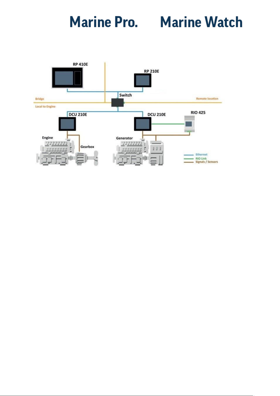
Overview of the 200E
Series
The drawing above shows a typical
layout.
DCU 210E Engine Controller
The DCU 210E engine controller is the
main building block in the 200 Series.
Engine sensor values are displayed on
the color touch screen, and commands
and other user interaction is also here.
DCU 208E Engine Controller
The DCU 208E is basically the same as
the DCU 210E, but without the color
touch screen.
It saves cost being used in smaller
engine rooms, where a remote panel is
all that is needed.
Configuration
An ordinary PC web-browser is used
to configure the DCU, using the inbuilt
web-server on the DCU.
RP 210E/220E/206E Remote
Panel
The optional RP remote panel brings
everything on the DCU to a remote
location, with the exact same user
interface. It does not need any
configuration, as it is reading the
configuration from the DCU.
Other manuals for Marine Pro 200E Series
1
This manual suits for next models
8
Table of contents
Other auto maskin Marine Equipment manuals

auto maskin
auto maskin S Series User manual

auto maskin
auto maskin Marine Watch S Series User manual

auto maskin
auto maskin 1006451 User manual

auto maskin
auto maskin Marine Pro 400 Series User manual

auto maskin
auto maskin Marine Pro Series User manual

auto maskin
auto maskin Marine Pro DCU 410E User manual

auto maskin
auto maskin Marine Pro 400 Series User manual

auto maskin
auto maskin Marine Pro 400 Series Instruction sheet

auto maskin
auto maskin Marine Pro 400 Series User manual

auto maskin
auto maskin Marine Pro 200 Series User manual


