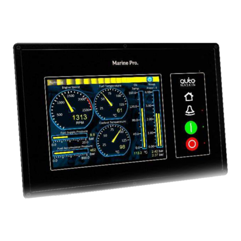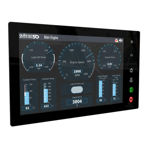
Copyright © Auto-Maskin AS, 2016
Max ripple 10% without exceeding Min and Max values.
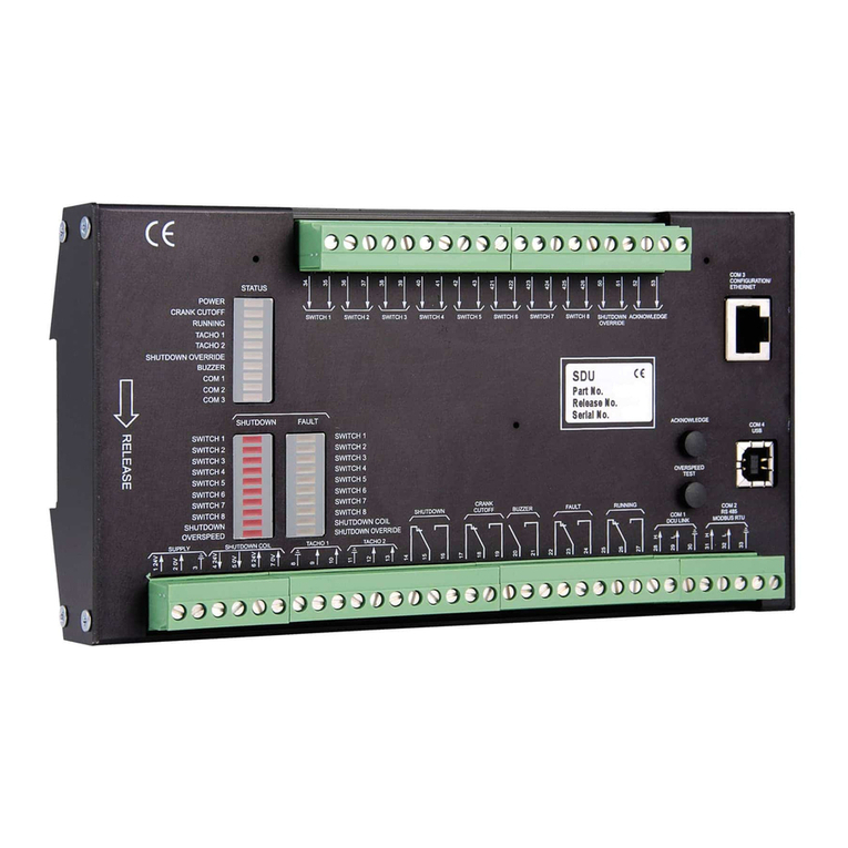
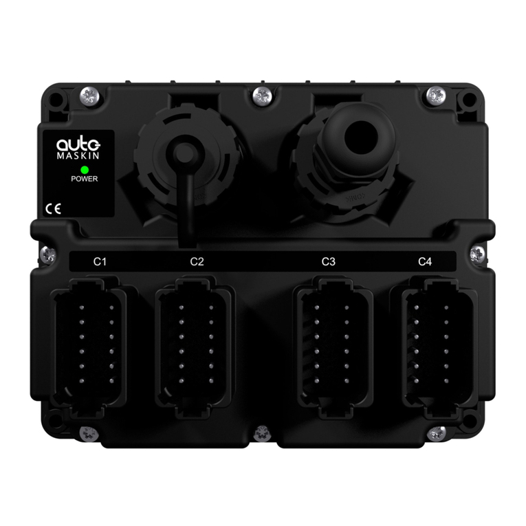
Rear side and Connectors
COM 3,
Modbus
TCP
Ethernet
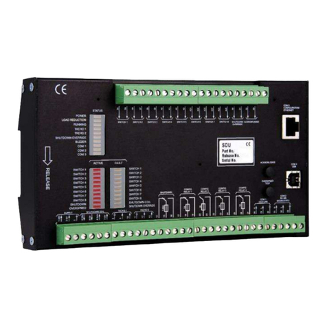
Power, Switch Inputs 1-4, Relay 1-4, COM1, COM2, Chassis-GND
This Remote Panel is designed to work
together with oe or ore DCUs ad its ai
purpose is to control the DCU from a remote
location.
1. Remove the unit from the ESD Bag. Use
the submitted Cabinet Frame and mount it
in a suitable enclosure.
2. Attach the Power Supply (Terminals 1-2)
and make sure the power ratings are
within product specifications.
3. Connect additional external connectors
which may include the following:
Relays
Switch Inputs
Ethernet Interface
COM Ports
For further details and information,
please see the Installation Manual.
At the first Power-Up the user will be guided
through a Setup Wizard:
1. Language selection and your choice is
valid through the rest of the procedure.
2. Network settings. Make sure to follow
common network configuration practice
and take care when several units need to
operate within the same network.
PC Connection/Setup:
Connect via Ethernet using a Net Browser
From the Address Field in the Browser,
type the IP-Address. Factory Default is
192.168.0.201.
Then log in to the unit. The Factory
Default password is ’.
(No User Name).
Version Information and the IP Address can
be shown on the screen by selecting:
Menu>Help>Version Information.
For further details and information, please
see the Configuration Manual.
Responsibilites:
It is the sole responsibility of the installer to ensure that
the installation work is carried out in a satisfactorily
manner and meet all applicable rules and regulations.
Note:
Auto-Maskin continuously upgrades its products and
reserves the right to make changes and improvements
without prior notice.
Additional Documentation:
Please visit the Marine Pro 400 section of the Auto-Maskin
website for the following enhanced documentation:
Installation Manual
Configuration Manual
Users Maual.
http://www.auto-maskin.com
