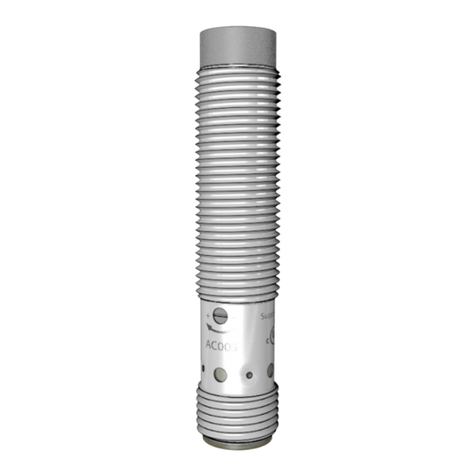
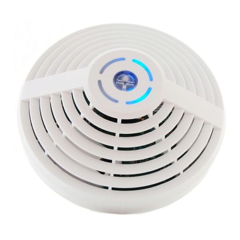
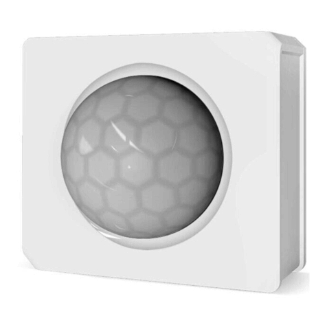
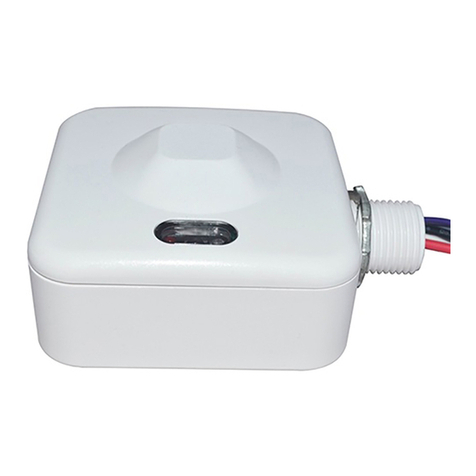
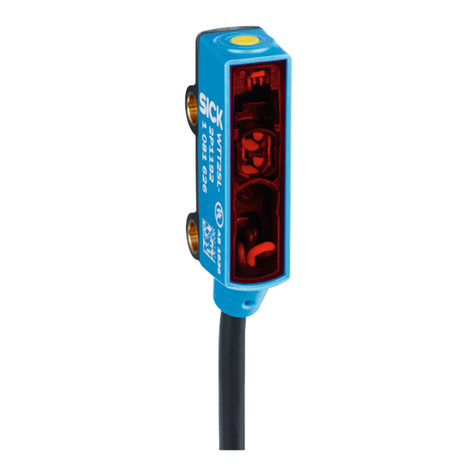
autosen AU001 User manual

Bedienungsanleitung
Ultraschallsensor und Ultraschall
Reflextaster
Operating instructions
Ultrasonic diffuse reflective sensors
Notice d‘utilisation
Détecteur à ultrasons
Istruzioni per l‘uso Sensore a
ultrasuoni a diffusione diretta
autosen AU001-AU003
autosen AU004-AU010
200479 / 00 01 / 2019
DE
UK
FR
IT

2
1 Vorbemerkung
Verwendete Symbole
►Handlungsanweisung
> Reaktion, Ergebnis
→Querverweis
Wichtiger Hinweis: Fehlfunktionen oder Störungen sind bei Nichtbeachtung möglich.
Information; Ergänzender Hinweis.
2 Sicherheitshinweise
Montage, elektrischer Anschluss, Inbetriebnahme, Bedienung und Wartung des Gerätes dürfen nur durch ausgebilde-
tes, vom Anlagenbetreiber autorisiertes Fachpersonal durchgeführt werden.
3 Bestimmungsgemäße Verwendung
Ultraschallsensoren erfassen berührungslos Objekte unterschiedlichster Materialien. Erkannte Objekte werden, je nach
gewähltem Sensor, über Schaltausgänge gemeldet oder deren Abstand mittels proportionalem Analogsignal
signalisiert.
4 Montage
AU001-AU003 AU004-AU010
1: Status LED P1 (gelb)
2: Echo-LED (grün)
3: Einstelltaste
►Objekt positionieren.
►Ultraschallsensor auf das Objekt oder den Hintergrund ausrichten und mit Hilfe einer Montagehalterung befestigen.
> Objekt / Hintergrund wird erkannt wenn die Echo-LED (grün) leuchtet.
Schallabsorbierende Oberflächen wirken sich negativ auf eine sichere Funktion aus.
Bei der Montage des Geräts ist die jeweilige Blindzone zu berücksichtigen!

3
1: Sensor
2: Target (zu erfassendes Objekt)
3: Schaltabstand
4: Blindzone
5 Elektrischer Anschluss
►Anlage spannungsfrei schalten.
►Gerät (abhängig vom gewählten Typ) anschließen:
Adernfarben
BK schwarz
BN braun
BU blau
WH weiß
Colours to DIN EN 60947-5-2
OUT1 Schaltausgang
OUT2 Teach: Programmierleitung
Adernfarben
BK schwarz
BN braun
BU blau
WH weiß
Colours to DIN EN 60947-5-2
OUT1 Schaltausgang - IO-Link
OUT2 Analogausgang
Technische Daten und weitere Informationen unter → www.autosen.com
L-
L+
BN
BU
WH
4
2 1
3
BK
2:Teach
4
2 1
3
BN
BU
WH
BK
L-
L+
Pin 4: IO-Link
AU001-AU003
AU004-AU010

4
6 Inbetriebnahme
Zur Inbetriebnahme ist das LED Verhalten zu beachten:
Echo-LED grün
Ein Echo wird empfangen.
Aus Kein Echo (Objekt / Hintergrund nicht erkannt).
Aus Für die Dauer des Rücksetzen auf Werkseinstellung.
Status LEDs gelb
Funktionsbestätigung
Blinkt 1 Hz Programmiermodus aktiv.
Blinkt 2,5 Hz Einstellung Abstand P1 abgeschlossen.
Blinkt 4 Hz Einstellung Abstand P2 abgeschlossen oder
Übernahmebestätigung der Einstellung.
Blinkt >10 Hz Invertieren des Schaltverhaltens.
7 Einstellungen
7.1 AU001-AU003
Teach mit L+
L+
L
1
4
3
OUT
2WH
BN
BK
BU
►Programmiermodus des Geräts starten.
► Teacheingang 2 s...6 s verbinden → 7 Leitungsteach.
> LED blinkt (1 Hz).
7.2 AU004-AU010
►Programmiermodus des Geräts starten.
►Taste 2 s...6 s drücken
> LEDs blinken (1 Hz).
AU001-AU010
Bei nicht erfolgreich abgeschlossener Programmierung kehrt das Gerät in die vorherige Einstellung zurück.
AU004-AU010: Dieses Gerät verfügt über eine IO-Link-Kommunikationsschnittstelle. Sobald Informationen zu
IO-Link und Einsatzmöglichkeiten → www.autosen.com.

5
8 Fensterfunktion Abstand P1 > P2
AU001-AU003
►Programmiermodus des Geräts starten.(7.1)
►Objekt auf Position P1.
►Teacheingang ca. 1 s verbinden.
> LED blinkt (2,5 Hz).
►Objekt auf Position P2.
►Teacheingang ca. 1 s verbinden.
> LED blinkt (4 Hz).
> Bei nicht erfolgreich abgeschlossener
Programmierung, blinkt die LED nicht und
das Gerät kehrt in die vorherige Einstellung
zurück.
AU004-AU010
►Programmiermodus des Geräts starten.(7.2)
►Objekt auf Position P1.
►Taste 1 x 1 s drücken
> LED blinkt (2,5 Hz).
►Objekt auf Position P2.
►Taste 1 x 1 s drücken
> LED blinkt (4 Hz).
> Bei nicht erfolgreich abgeschlossener
Programmierung, blinkt die LED nicht und
das Gerät kehrt in die vorherige Einstellung
zurück.
B P2 P1
Y
X
1
Ausgangsverhalten Schaltausgang
X: Abstand
Y: Ausgangsverhalten
①: OUT1: (Schaltausgang)
B: Blindzone
P1: Einstellpunkt 1
P2: Einstellpunkt 2
B P2 P1
Y
X
Y
X
1
2
Ausgangsverhalten Schalt- / Analogausgang
X: Abstand
Y: Ausgangsverhalten
①: OUT1: (Schaltausgang)
②: OUT2: (Analogausgang)
B: Blindzone
P1: Einstellpunkt 1 (OUT1
P2: Einstellpunkt 2 (OUT2)

6
9 Hysteresefunktion P1 = P2
AU001-AU003
►Programmiermodus des Geräts starten.(7.1)
►Objekt auf Position P1.
►Teacheingang ca. 1 s verbinden.
> LED blinkt (2,5 Hz).
►Objekt auf Position P2.
►Teacheingang ca. 1 s verbinden.
> LED blinkt (4 Hz).
> Bei nicht erfolgreich abgeschlossener
Programmierung, blinkt die LED nicht und
das Gerät kehrt in die vorherige Einstellung
zurück.
AU004-AU010
►Programmiermodus des Geräts
starten.(7.2)
►Objekt auf Position P1.
►Taste 1 x 1 s drücken
> LED blinkt (2,5 Hz).
►Objekt auf Position P2.
►Taste 1 x 1 s drücken
> LED blinkt (4 Hz).
> Bei nicht erfolgreich abgeschlosse-
ner Programmierung, blinkt die LED
nicht und das Gerät kehrt in die
vorherige Einstellung zurück.
B P1/P2
Y
X
Y
X
1
2
Ausgangsverhalten Schalt-/
Analogausgang
X: Abstand
Y: Ausgangsverhalten
①: OUT1: (Schaltausgang)
②: OUT2: (Analogausgang)
B: Blindzone
P1: Einstellpunkt 1 (OUT1)
P2: Einstellpunkt 2 (OUT2)
B P1/P2
Y
X
1
Ausgangsverhalten Schaltausgang
X: Abstand
Y: Ausgangsverhalten
①: OUT1: (Schaltausgang)
B: Blindzone
P1: Einstellpunkt 1
P2: Einstellpunkt 2

7
10 Invertieren des Ausgangsverhaltens
► Teacheingang > 6 s verbinden → 7 Leitungsteach. (AU001-AU003)
►Taste > 6 s drücken. (AU004-AU010)
> LED blinkt (> 10 Hz).
> Ausgangsfunktionen werden invertiert (NO wird NC ode
r umgekehrt).
11 Werkseinstellung herstellen
►Gerät so ausrichten, dass kein Echo empfangen wird.
►Gerät in Programmiermodus schalten. (7.)
► Teacheingang 1 s verbinden → 7 Leitungsteach. (AU001-AU003)
►Taste 1 x 1 s drücken. (AU004-AU010)
> LED blinkt kurz mit 4 Hz.
12 Betrieb
►Prüfen, ob das Gerät sicher funktioniert.
> Anzeige durch LEDs:
LED grün leuchtet Echo wird empfangen.
LED gelb leuchtet Schaltausgang ist geschaltet.
LED grün blinkt Kurzschluss am Ausgang.
Der Mindestabstand zwischen dem „Metallgehäuse des Näherungsschalters“ und einem „außerhalb des Sensors
befindlichen, nicht isolierten Teil“ muss mindestens 12,7 mm betragen
13. Funktionsweise eines Ultraschallsensors
1: Anschluss
2: Gehäuse
3: Elektronik
4: Schallwandler
5: Ultraschallkeule
6: Objekt

8
Wichtige Begriffe
Aktive Schaltzone / Aktive Zone Bereich (Raum) über der aktiven Fläche, in dem der
Sensor auf die Näherung von Objekten reagiert.
Blindzone Nahbereich vor dem Schallwandler der keine
Laufzeitmessung zulässt
Ausgangsfunktion Schließer: Objekt im Bereich der aktiven Zone
> Ausgang durchgeschaltet.
Öffner: Objekt im Bereich der aktiven Zone
> Ausgang gesperrt.
Programmierbar: Öffner oder Schließer frei wählbar.
p-schaltend: Ausgangssignal positiv (gegen L–).
n-schaltend: Ausgangssignal negativ (gegen L+).
Bemessungsisolationsspannung DC-Geräte mit Schutzklasse III: 60 V DC
Bemessungskurzschlussstrom bei kurzschlussfesten Geräten: 100 A
Bemessungsstoßspannungs-festigkeit DC-Geräte mit Schutzklasse III: 60 V DC: 0,8 kV
(Überspannungskategorie II)
Bereitschaftsverzögerungszeit Zeit, die der Sensor benötigt, um nach Anlegen
der Betriebsspannung funktionsbereit zu sein (im
Millisekundenbereich).
Betriebsspannung Spannungsbereich, in dem der Sensor sicher arbeitet. Es
sollte eine stabilisierte und gut geglättete Gleichspannung
verwendet werden! Restwelligkeit beachten!
Gebrauchskategorie DC-Geräte: DC-13 (Steuerung von Elektromagneten)
Hysterese Differenz zwischen Ein- und Ausschaltpunkt.
Kurzschlussschutz Sind autosen-Sensoren durch getakteten
Kurzschlussschutz gegen Überstrom geschützt, kann bei
Glühlampen, elektronischen Relais oder niederohmigen
Verbrauchern der Kurzschlussschutz ansprechen!
Produktnorm IEC 60947-5-2
Schaltpunktdrift Verschiebung des Schaltpunktes bei Veränderung der
Umgebungstemperatur.
Stromaufnahme Der Strom zur Eigenversorgung von Gleichstromgeräten.

9
14. Mindestabstände zur Montage gleichartiger Geräte
14.1 Gegenüberliegende Montage von Ultraschallsensoren
Version Reichweite [mm] Abstand X [mm]
AU001 300 2200
AU002 800 3000
AU003 1200 3800
AU004 400 2800
AU005 900 4000
AU006 1600 5000
AU007 2200 6600
AU008 3500 10500
AU009 6000 18000
AU010 8000 24000
Die sichere Funktion in der gewählten Applikation ist zwingend zu prüfen.
X

10
14.2 Montage nebeneinander von Ultraschallsensoren
Version Reichweite [mm] Abstand Y [mm]
AU001 300 260
AU002 800 280
AU003 1200 550
AU004 400 450
AU005 900 600
AU006 1600 720
AU007 2200 840
AU008 3500 1400
AU009 6000 1600
AU010 8000 2150
Die sichere Funktion in der gewählten Applikation ist zwingend zu prüfen.
Y

11
1 Preliminary note
Symbols used
►Instructions
> Reaction, result
→Cross-reference
Important note: Non-compliance may result in malfunction or interference.
Information; Supplementary note.
2 Safety instructions
Installation, electrical connection, set-up, operation and maintenance of the unit must be carried out by qualified person-
nel authorised by the machine operator.
3 Functions and features
Ultrasonic sensors detect objects of various materials without any contact. Depending on the selected sensor, detected
objects are signalled via switching outputs or their distance is indicated by means of a proportional analogue signal.
4 Installation
AU001-AU003 AU004-AU010
1: Status LED P1 (yellow)
2: Echo LED (green)
3: Set button
►Position object.
►Align the ultrasonic sensor so that it directly faces the object or the background and secure it to a bracket.
> Object / background is detected when the echo LED (green) lights.
Sound-absorbing surfaces have a negative effect on a reliable function.
During installation of the device, consider the blind zone.
1: Sensor
2: Target (object to be detected)
3: Sensing range
4: Blind zone

12
5 Electrical connection
►Disconnect power.
►Connect device (depending on the type selected):
Cor colours
BK black
BN brown
BU blue
WH white
Colours to DIN EN 60947-5-2
OUT1 Switching output
OUT2 Teach: Programming wire
Cor colours
BK black
BN brown
BU blue
WH white
Colours to DIN EN 60947-5-2
OUT1 Switching output - IO-Link
OUT2 Analogue output
Technical data and further information at → www.autosen.com
6 Set-up
Note the LED behaviour for the set-up:
Echo LED green
On Echo is received.
Off No echo (object / background not detected).
Off For the time of resetting to factory setting.
Status LEDs yellow
Function acknowledgement
Flashes 1 Hz Programming mode active.
Flashes 2.5 Hz Setting distance P1 completed.
Flashes 4 Hz Setting distance P2 completed or
assignment acknowledgement of the setting.
Flashes 10 Hz Inverting the switching characteristics.
L-
L+
BN
BU
WH
4
2 1
3
BK
2:Teach
4
2 1
3
BN
BU
WH
BK
L-
L+
Pin 4: IO-Link
AU001-AU003
AU004-AU010

13
7 Settings
7.1 AU001-AU003
Teach with L+
L+
L
1
4
3
OUT
2WH
BN
BK
BU
►Start programming mode of the device.
► Connect teach input, 2 s...6 s → 7 Wire programming.
> LED flashes (1 Hz).
7.2 AU004-AU010
►Start programming mode of the device.
►Press button 2 s...6 s.
> LEDs flash (1 Hz).
AU001-AU010
If programming has not been completed successfully, the device returns to the previous setting.
AU004-AU010: This unit has an IO-Link communication interface. You will find more detailed information about
IO-Link and usage at www.autosen.com.
8 Window function, distance P1 > P2
AU001-AU003
Start programming mode of the device. (7.1)
►Object in position P1.
►Connect teach input approx. 1 s.
> LED flashes (2.5 Hz).
►Object in position P2.
►Connect teach input approx. 1 s.
> LED flashes (4 Hz).
> If programming is not completed success-
fully, the LED does not flash and the instru-
ment returns to the previous setting.
B P2 P1
Y
X
1
Output response
of the switching
X: Distance
Y: Comportamento dell‘uscita
①: OUT1: (switching output)
B: Blind zone
P1: Setting point 1
P2: Setting point 2

14
AU004-AU010
Start programming mode of the device. (7.2)
►Object in position P1.
►Press button once 1 s.
> LED flashes (2.5 Hz).
►Object in position P2.
> Press button once 1 s.
> LED flashes (4 Hz).
> If programming is not completed
successfully, the LED does not flash and
the instrument returns to the previous
setting.
9 Hysteresefunktion P1 = P2
AU001-AU003
Start programming mode of the device. (7.1)
►Objekt auf Position P1.
►Teacheingang ca. 1 s verbinden.
> LED blinkt (2,5 Hz).
►Objekt auf Position P2.
►Teacheingang ca. 1 s verbinden.
> LED blinkt (4 Hz).
> If programming is not completed
successfully, the LED does not flash and
the instrument returns to the previous
setting.
Output response of the switching
X: Distance
Y: Comportamento dell‘uscita
①: OUT1: (switching output)
B: Blind zone
P1: Setting point 1
P2: Setting point 2
B P2 P1
Y
X
Y
X
1
2
Output response of the switching / analogue output
X: Distance
Y: Output response
①: OUT1 (switching output)
②: OUT2 (switching output / analogue output)
B: Blind zone
P1: Setting point 1 (OUT1)
P2: Setting point 2 (OUT2)
B P1/P2
Y
X
1

15
AU004-AU010
Start programming mode of the device.
(7.2)
►Objekt auf Position P1.
►Taste 1 x 1 s drücken
> LED blinkt (2,5 Hz).
►Objekt auf Position P2.
►Taste 1 x 1 s drücken
> LED blinkt (4 Hz).
> If programming is not completed
successfully, the LED does not
flash and the instrument returns to
the previous setting.
10 Inverting the output response
► Connect teach input > 6 s → 7 Wire programming. (AU001-AU003)
►Press button > 6 s. (AU004-AU010)
> LED flashes (> 10 Hz).
> Output functions are inverted (NO becomes NC or vice versa).
11 Restore factory setting
►Align the device so that no echo is received.
►Go into the programming mode of the unit.
► Connect teach input 1 s → 7 Wire programming. (AU001-AU003)
►Press button once for 1 s. (AU004-AU010)
> LED flashes shortly with 4 Hz.
12 Operation
►Check whether the unit operates correctly.
> Display by LEDs:
Green LED is lit. Echo is received.
Yellow LED is lit. Switching output is switched.
Green LED flashes. Short circuit at the output.
The minimum distance between the “Proximity Switch Metal Enclosure“ and any “External uninsulated live part“
shall be at least 12.7 mm.
B P1/P2
Y
X
Y
X
1
2
Output response of the switching
/ analogue output
X: Distance
Y: Output response
①: OUT1 (switching output)
②: OUT2 (switching output / analogue output)
B: Blind zone
P1: Setting point 1 (OUT1)
P2: Setting point 2 (OUT2)

16
13. Operating principle of an ultrasonic sensor
1: Connection
2: Housing
3: Electronics
4: Sound transducer
5: Ultrasound cone
6: Object
Glossary of important terms
Active zone Area in front of the sensing face in which the sensor reacts
to the approach of the target.
Blind zone Area close to the sound transducer which allows no time of
ight measurement.
Output function Normally open: object in the active zone
> output switched.
Normally closed: object in the active zone
> output blocked.
Programmable: choice between normally closed
or normally open.
Positive switching: positive output signal (to L-).
Negative switching: negative output signal (to L+).
Rated insulation voltage DC units with protection class III: 60 V DC.
Rated short-circuit current For short-circuit-proof units: 100 A.
Rated impulse withstand voltage DC units with protection class III: 60 V DC: 0.8 kV
(overvoltage category II).
Power-on delay time The time the sensor needs to be ready for operation after
application of the operating voltage (in the millisecond
range).
Operating voltage Voltage range in which the sensor operates reliably. A
stabilised and smoothed direct voltage should be used!
Take into account residual ripple!
Utilisation category DC units: DC-13 (control of solenoids).
Hysteresis Difference between switch-on and switch-off point.
Short-circuit protection autosen sensors are protected against excessive current
by means of a pulsed short-circuit protection. The inrush
current of incandescent lamps, electronic relays and low
resistance loads may cause this protection to cut in and
turn the sensor off.
Product standard IEC 60947-5-2.

17
Glossary of important terms
Switch point drift The shifting of the switch point if the ambient temperature
changes.
Current consumption Current for the internal supply of DC units.
14. Minimum distances for the installation of identical units
14.1 Opposite installation of ultrasonic sensors
Version Range [mm] Distance X [mm]
AU001 300 2200
AU002 800 3000
AU003 1200 3800
AU004 400 2800
AU005 900 4000
AU006 1600 5000
AU007 2200 6600
AU008 3500 10500
AU009 6000 18000
AU010 8000 24000
Checking the reliable function in the selected application is imperative.
X

18
14.2 Side-by-side installation of ultrasonic sensors
Version Range [mm] Distance Y [mm]
AU001 300 260
AU002 800 280
AU003 1200 550
AU004 400 450
AU005 900 600
AU006 1600 720
AU007 2200 840
AU008 3500 1400
AU009 6000 1600
AU010 8000 2150
Checking the reliable function in the selected application is imperative.
Y

19
1 Remarques préliminaires
Verwendete Symbole
►Action à faire
> Retour d'information, résultat
→Référence croisée
Remarque importante
Le non-respect peut aboutir à des dysfonctionnements ou perturbations.
Information
Remarque supplémentaire.
2 Consignes de sécurité
Le montage, le raccordement électrique, la mise en service, le fonctionnement et l‘entretien de l‘appareil doivent être
effectués par du personnel qualifié et autorisé par le responsable de l‘installation.
3 Fonctionnement et caractéristiques
Des détecteurs à ultrasons détectent sans contact des objets de différentes matières. Suivant le détecteur choisi, les
objets détectés sont indiqués via les sorties de commutation ou leur distance est signalée au moyen d‘un signal
analogique proportionnel.
4 Montage
AU001-AU003 AU004-AU010
1: Etat LED P1 (jaune)
2: LED écho (verte)
3: Bouton de réglage
►Positionner l‘objet.
►Orienter le détecteur à ultrasons vers l‘objet ou l‘arrière-plan et le fixer à l‘aide d‘une platine de fixation.
> L‘objet / l‘arrière-plan est détecté si la LED écho (verte) est allumée.
Des surfaces qui absorbent le son rendent le fonctionnement moins fiable.
Faire attention à la zone aveugle respective lors du montage de l‘appareil !
1: Détecteur
2: Cible (objet à détecter)
3: Portée
4: Zone morte

20
5 Raccordement électrique
►Mettre l‘installation hors tension.
►Raccorder l‘appareil (dépendant du type choisi) :
Couleurs des fils conducteurs
BK noir
BN brun
BU bleu
WH blanc
Colours to DIN EN 60947-5-2
OUT1 sortie de commutation
OUT2 Apprentissage : fil de programmation
Couleurs des fils conducteurs
BK noir
BN brun
BU bleu
WH blanc
Colours to DIN EN 60947-5-2
OUT1 sortie de commutation - IO-Link
OUT2 analogique
Données techniques et plus d‘informations sur→ www.autosen.com
6 Mise en service
Pour la mise en service, vérifier le comportement LED:
LED écho verte
Activé L'écho est reçu.
Désactivée Aucun écho (objet / arrière-plan non pas détecté).
Désactivée Pour la durée de la remise au réglage usine.
LED d'état jaunes
Confirmation du fonctionnement
Clignote (1 Hz) Mode de programmation activé.
Clignote (2,5 Hz) Réglage de la distance P1 achevé.
Clignote (4 Hz) Réglage de la distance P2 achevé ou
confirmation de l'acceptation du réglage.
Clignote (10 Hz) Inversion du comportement de commutation.
L-
L+
BN
BU
WH
4
2 1
3
BK
2:Teach
4
2 1
3
BN
BU
WH
BK
L-
L+
Pin 4: IO-Link
AU001-AU003
AU004-AU010
This manual suits for next models
9
Table of contents
Languages:
Other autosen Accessories manuals
autosen
autosen AF003 User manual
autosen
autosen AC004 Manual

autosen
autosen AF004 User manual

autosen
autosen AP Series User manual
autosen
autosen AF005 User manual
autosen
autosen AI006 User manual
autosen
autosen AP008 User manual
autosen
autosen AL001 User manual

autosen
autosen AU011 User manual
autosen
autosen AL002 User manual


