Avdel 74110 User manual
Instruction Manual
Original Instruction
Threaded Insert Power Tool
74110


3
Contents
Safety Rules 4
Tool Specifications 5
Tool Dimensions 5
Intent of Use
Tool Selection 6 & 7
Putting into Service
Air supply 8
Operating Procedure 8
Clutch Adjustment 9
Accessories 9
Nose Assemblies
Fitting Instructions 10
Servicing Instructions 10
Nose Assembly Components 11 & 12
Servicing the Tool
Daily Servicing 13
Weekly Servicing 13
Safety Data (Grease) 14
Maintenance
Reset Clutch Torque 15
Clutch Assembly 16
Gearbox Assembly 17
Motor Assembly 18
Setting the Push Rod 19
General Assembly of Base Tool 20, 22
Parts List 21, 23
Troubleshooting 24 & 25
Avdel UK Limited policy is one of continuous product development and improvement and we reserve the right to change the specification of any product without prior notice.
Warranty
Avdel installation tools carry a 12 month warranty against defects caused by faulty materials or
workmanship, the warranty period commencing from the date of delivery confirmed by invoice or delivery
note.
The warranty applies to the user/purchaser when sold through an authorised outlet, and only when used for
the intended purpose. The warranty is invalidated if the installation tool is not serviced, maintained and
operated according to the instructions contained in the Instruction and Service Manuals.
In the event of a defect or failure, and at its sole discretion, Avdel undertakes only to repair or replace faulty
components.

4
Safety Rules
1Do not use outside the design intent.
2Do not use equipment with this tool other than that recommended and supplied by Avdel UK Limited.
3Any modification undertaken by the customer to the tool/machine, nose assemblies, accessories or any equipment
supplied by Avdel UK Limited or their representatives, shall be the customer’s entire responsibility. Avdel UK Limited
will be pleased to advise upon any proposed modification.
4The tool/machine must be maintained in a safe working condition at all times and examined at regular intervals for
damage and function by trained competent personnel. Any dismantling procedure shall be undertaken only by
personnel trained in Avdel UK Limited procedures. Do not dismantle this tool/machine without prior reference to the
maintenance instructions. Please contact Avdel UK Limited with your training requirements.
5The tool/machine shall at all times be operated in accordance with relevant Health and Safety legislation. In the U.K.
the “Health and Safety at Work etc. act 1974” applies. Any question regarding the correct operation of the
tool/machine and operator safety should be directed to Avdel UK Limited.
6The precautions to be observed when using this tool/machine must be explained by the customer to all operators.
7Always disconnect the airline from the tool/machine inlet before attempting to adjust, fit or remove a nose
assembly.
8Do not operate a tool/machine that is directed towards any person(s).
9Ensure that vent holes do not become blocked or covered and that hoses are always in good condition.
10 The operating pressure shall not exceed 6.3 bar - 94 lbf/in2.
11 Do not operate the tool without full nose equipment in place.
12 When using the tool, the wearing of safety glasses is required both by the operator and others in the vicinity to
protect against fastener projection, should a fastener be placed ‘in air’. We recommend wearing gloves if there are
sharp edges or corners on the application.
13 Take care to avoid entanglement of loose clothes, ties, long hair, cleaning rags etc. in the moving parts of the tool
which should be kept dry and clean for best possible grip.
14 When carrying the tool from place to place keep hands away from the trigger/lever to avoid inadvertent start up.
15 Always adopt a firm footing or a stable position before operating the tool and be aware of a torque reaction on the
hands when the tool is operating, particularly during the reversing sequence. Grip the tool firmly to be able to
counter the torque reaction, but not too tightly.
16 Keep hands away from the rotating drive screw and the nose end of the tool. If a fastener becomes jammed on the
drive screw, shut off the air supply and drain the supply line to the tool before attempting to dislodge it.
17 The tool is not electrically insulated.
18 This tool is not designed for use in combustible or explosive atmospheres.
This instruction manual must be read with particular attention to the following safety rules, by any
person installing, operating, or servicing this tool.

5
Tool Specification
Tool Dimensions
Specifications
Air Pressure Minimum - Maximum 4-6.3 bar (60/94 lbf/in2)
Free Air Volume Required @ 6.3 bar / 94 lbf/in27.5 litres/sec
Motor Speed @ 75 lb/in2minimum 600 rpm (clockwise)
Cycle time Approx 3 seconds
Noise Level 82 dB(A)
Weight Without nose equipment 1.6 kg 3.53 lb)
Vibration Less than 2.5 m/s2(8 ft/s2 )
263
A
B
10.350
170
6.700
Dimensions shown in bold are millimetres. Other dimensions are in inches

6
Tool Selection
Intent of Use
The pneumatic 74110 type tool is designed to place Avdel®threaded inserts at high speed making it ideal for batch or
flow-line assembly in a wide variety of applications throughout all industries.
Use the selection table opposite to select a complete tool which will be fitted with the correct nose assembly for the
threaded insert selected. ‘A’ and ‘B’ dimensions will help you assess the accessibility of your application.
It is also possible to order the base tool only (part number 74110-12000). For details of Nose Assemblies see pages 11
and 12.
3
/
16
BSW
20 - 25 84100-15000 13 12
1
/
215
/
32
07556-09816 74110-00016
1
/
4
BSW
25 - 30 84100-15000 13 15
1
/
219
/
32
07566-09818 74110-00018
5
/
16
BSW
40 - 45 84110-15000 14 14
9
/
16 9
/
16
07443-09810 74110-00010
3
/
8
BSW
50 - 55 84110-15000 16 10
5
/
813
/
32
07443-09812 74110-00012
1
/
4
BSW
25 - 30 84100-15000 13 15
1
/
219
/
32
07556-09828 74110-00028
5
/
16
BSW
40 - 45 84110-15000 14 14
9
/
16 9
/
16
07443-09820 74110-00020
3
/
8
BSW
50 - 55 84110-15000 16 10
5
/
813
/
32
07443-09822 74110-00022
4
UNC
5 - 7 84100-15020 13 12
1
/
215
/
32
07556-09854 74110-00054
6
UNC
9 - 11 84100-15010 13 12
1
/
215
/
32
07556-09856 74110-00056
8
UNC
13 - 15 84100-15010 13 10
1
/
213
/
32
07556-09858 74110-00058
10
UNC
20 - 25 84100-15000 13 12
1
/
215
/
32
07556-09850 74110-00050
6
UNF
9 - 11 84100-15010 13 12
1
/
215
/
32
07556-09876 74110-00076
8
UNF
13 - 15 84100-15010 13 10
1
/
213
/
32
07556-09878 74110-00078
10
UNF
20 - 25 84100-15000 13 12
1
/
215
/
32
07556-09870 74110-00070
1
/
4
UNC
25 - 30 84100-15000 13 15
1
/
219
/
32
07566-09848 74110-00048
5
/
16
UNC
40 - 45 84110-15000 14 14
9
/
16 9
/
16
07443-09840 74110-00040
3
/
8
UNC
50 - 55 84110-15000 16 10
5
/
813
/
32
07443-09842 74110-00042
1
/
4
UNF
25 - 30 84100-15000 13 15
1
/
219
/
32
07556-09868 74110-00068
5
/
16
UNF
40 - 45 84110-15000 14 14
9
/
16 9
/
16
07443-09860 74110-00060
3
/
8
UNF
50 - 55 84110-15000 16 10
5
/
813
/
32
07443-09862 74110-00062
6
BA
5 - 7 84100-15020 13 15
1
/
219
/
32
07556-09836 74110-00036
4
BA
9 - 11 84100-15010 13 12
1
/
215
/
32
07556-09834 74110-00034
2
BA
20 - 25 84100-15000 13 12
1
/
215
/
32
07556-09832 74110-00032
0
BA
25 - 30 84100-15000 13 12
1
/
215
/
32
07556-09830 74110-00030
M3 5 - 7 84100-15020 13 12
1
/
215
/
32
07556-09883 74110-00083
M4 13 - 15 84100-15010 13 10
1
/
213
/
32
07556-09884 74110-00084
M5 20 - 25 84100-15000 13 12
1
/
215
/
32
07556-09885 74110-00085
M6 25 - 30 84100-15000 13 15
1
/
219
/
32
07556-09886 74110-00086
M8 40 - 45 84110-15000 14 14
9
/
16 9
/
16
07443-09888 74110-00088
M10 50 - 55 84110-15000 16 12
5
/
815
/
32
07443-09880 74110-00080
M4 16 - 18 84100-15010 13 10
1
/
213
/
32
07556-09184 74110-04084
M5 30 - 35 84110-15000 13 12
1
/
215
/
32
07556-09185 74110-04085
M6 35 - 40 84110-15000 13 15
1
/
219
/
32
07556-09186 74110-04086
M4 16 - 18 84110-15010 13 12
1
/
215
/
32
07556-09284 74110-06084
M5 30 - 35 84110-15000 13 12
1
/
215
/
32
07556-09285 74110-06085
M6 40 - 45 84110-15000 16 14
5
/
89
/
16
07556-09286 74110-06086
M8 50 - 55 84110-15000 16 15
5
/
819
/
32
07443-09288 74110-06088
M5 30 - 35 84110-15000 10 13
13
/
32 1
/
2
07528-07085 74110-07085
M6 40 - 45 84110-15000 13 15
1
/
219
/
32
07566-09186 74110-04086
74110 TOOL SELECTION
NOSE (see drawing opposite for A & B)
TORQUE
SETTING (lbf ins)
Ø
COMPLETE
TOOL PART Nº
NOSE ASSY PART N º
A (mm)
INSERT
NAME & SERIES B (mm) A (in) B (in)
UNSET
CLUTCH PART Nº
STANDARD
NUTSERTS
(9500)
(9538)
L/F THIN SHEET
NUTSERT®
(9698)
HEXSERT®
(9688)
NUTSERT®SQ
(GK08)

7
Tool Selection
Intent of Use
74110 TOOL SELECTION
NOSE (see drawing opposite for A & B)
TORQUE
SETTING (lbf ins)
Ø
COMPLETE
TOOL PART Nº
NOSE ASSY PART Nº
A (mm)
INSERT
NAME & SERIES B (mm) A (in) B (in)
UNSET
CLUTCH PART Nº
THIN
3
/
16
BSW
30 - 35 84110-15000 13 10
1
/
213
/
32
07556-09916 74110-01016
SHEET
1
/
4
BSW
35 - 40 84110-15000 13 13
1
/
21
/
217
/
32
07566-09918 74110-01018
NUTSERT
®
5
/
16
BSW
50 - 55 84110-15000 14 14
9
/
16 9
/
16
07443-09910 74110-01010
(9650)
1
/
4
BSF
35 - 40 84110-15000 13 13
1
/
21
/
217
/
32
07556-09928 74110-01028
5
/
16
BSF
50 - 55 84110-15000 14 14
9
/
16 9
/
16
07443-09920 74110-01020
4
UNC
7 - 9 84100-15020 13 11
1
/
27
/
16
07556-09954 74110-01054
6
UNC
16 - 18 84100-15010 13 11
1
/
27
/
16
07556-09956 74110-01056
8
UNC
16 - 18 84100-15010 13 12
1
/
215
/
32
07556-09958 74110-01058
10
UNC
30 - 35 84110-15000 13 10
1
/
213
/
32
07556-09950 74110-01050
4
UNF
7 - 9 84100-15020 13 11
1
/
27
/
16
07556-09974 74110-01074
6
UNF
16 - 18 84100-15010 13 11
1
/
27
/
16
07556-09976 74110-01076
8
UNF
16 - 18 84100-15010 13 12
1
/
215
/
32
07556-09978 74110-01078
10
UNF
30 - 35 84110-15000 13 10
1
/
213
/
32
07556-09970 74110-01070
1
/
4
UNC
35 - 40 84110-15000 13 13
1
/
21
/
217
/
32
07556-09948 74110-01048
5
/
16
UNC
50 - 55 84110-15000 14 14
9
/
16 9
/
16
07443-09940 74110-01040
1
/
4
UNF
35 - 40 84110-15000 13 13
1
/
21
/
217
/
32
07556-09968 74110-01068
5
/
16
UNF
50 - 55 84110-15000 14 14
9
/
16 9
/
16
07443-09960 74110-01060
6
BA
7 - 9 84100-15020 13 13
1
/
21
/
217
/
32
07556-09936 74110-01036
4
BA
16 - 18 84100-15010 13 11
1
/
27
/
16
07556-09934 74110-01034
2
BA
30 - 35 84110-15000 13 17
1
/
221
/
32
07556-09932 74110-01032
0
BA
35 - 40 84110-15000 13 11
1
/
27
/
16
07556-09930 74110-01030
M3 7 - 9 84100-15020 13 11
1
/
27
/
16
07556-09983 74110-01083
M4 16 - 18 84100-15010 13 11
1
/
27
/
16
07556-09984 74110-01084
M5 30 - 35 84110-15000 13 10
1
/
213
/
32
07556-09985 74110-01085
M6 35 - 40 84110-15000 13 13
1
/
21
/
217
/
32
07556-09986 74110-01086
M8 50 - 55 84110-15000 14 14
9
/
16 9
/
16
07443-09988 74110-01088
SUPERSERT
®
8
UNC
16 - 18 84100-15010 13 10
1
/
213
/
32
07552-09558 74110-02058
(FB00) 10
UNC
30 - 35 84110-15000 13 12
1
/
215
/
32
07552-09550 74110-02050
8
UNF
16 - 18 84100-15010 13 10
1
/
213
/
32
07552-09578 74110-02078
10
UNF
30 - 35 84110-15000 13 12
1
/
215
/
32
07552-09570 74110-02070
1
/
4
UNC
45 - 50 84110-15000 13 15
1
/
219
/
32
07552-09548 74110-02048
1
/
4
UNF
45 - 50 84110-15000 13 15
1
/
219
/
32
07552-09568 74110-02068
M3 16 - 18 84100-15010 13 19
1
/
23
/
4
07552-09583 74110-02083
M4 16 - 18 84100-15010 13 10
1
/
213
/
32
07552-09584 74110-02084
M5 30 - 35 84110-15000 13 11
1
/
27
/
16
07552-09585 74110-02085
M6 45 - 50 84110-15000 13 15
1
/
219
/
32
07552-09586 74110-02086
LGE FLANGE M4 16 - 18 84100-15010 13 10
1
/
213
/
32
07556-09184 74110-04084
HEXSERT
®
M5 30 - 35 84110-15000 13 10
1
/
213
/
32
07557-09285 74110-03085
(9498) M6 35 - 40 84110-15000 14 12
9
/
16 15
/
32
07556-09186 74110-04086

8
Air Supply
Operating Procedure
Putting into Service
All tools are operated with compressed air at an optimum pressure of 5.5 bar. We recommend the use of pressure regulators
and automatic oiling/filtering systems on the main air supply. These should be fitted within 3 metres of the tool (see diagram
below) to ensure maximum tool life and minimum tool maintenance.
Air supply hoses should have a minimum working effective pressure rating of 150% of the maximum pressure produced in the
system or 10 bar, whichever is the highest. Air hoses should be oil resistant, have an abrasion resistant exterior and should
be armoured where operating conditions may result in hoses being damaged. All air hoses MUST have a minimum bore
diameter of 6.4 millimetres or 1/4 inch.
Read servicing daily details page 13.
IMPORTANT
When placing Standard Nutserts, lubricate the drive screw of the tool every 25 placings. This is best
achieved by wiping the drive screw with a sponge soaked with STP Lubricant part number 07992-00013.
OPTION 1
•Ensure that the correct nose equipment is fitted.
•Connect the tool to the air supply.
•Place the insert into the prepared hole of the application.
•Locate the drive screw of the tool into the insert.
•Operate the lever. The drive screw will screw into and
collapse the insert, then automatically reverse out.
OPTION 2
•Ensure that the correct nose equipment is fitted.
•Connect the tool to the air supply.
•Screw the insert lip first onto the drive screw of the tool.
•With the insert on the tool, locate it into the prepared
hole of the application.
•Operate the lever. The drive screw will screw into and
collapse the insert, then automatically reverse out.
8
6
4
2
0
10
12
14
16
TAKE OFF POINT
FROM MAIN SUPPLY
STOP COCK
(USED DURING MAINTENANCE
OF FILTER/REGULATOR
OR LUBRICATION UNITS)
MAIN SUPPLY
DRAIN POINT
PRESSURE REGULATOR
AND FILTER
(DRAIN DAILY)
LUBRICATOR
3
M
E
T
R
E
S
9
Clutch Adjustment
Accessories
Putting into Service
If you have ordered a complete tool the clutch will be set for the specified insert.
When purchased as a spare part, the clutch is supplied unset.
Correct clutch setting is necessary to ensure optimum deformation of the insert. If the deformation is insufficient (clutch
torque too low) the insert will rotate in the application. If the deformation is excessive (clutch torque too high) thread distortion
will occur and extensive wear on the drivescrew, may lead to fracture.
For details on how to adjust the clutch refer to maintenance instructions referring to the clutch on page 15.
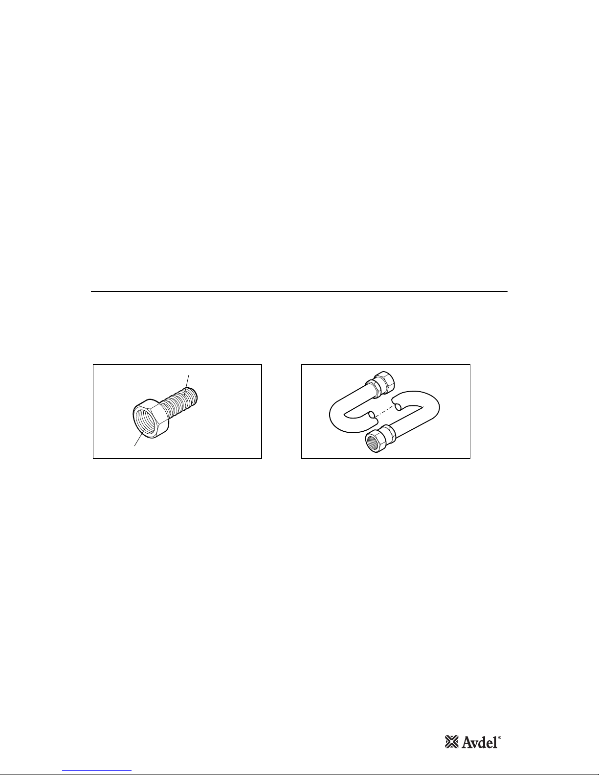
Two different accessories are available to make the connection to your air supply:
Hose Connector
part nº 07005-00276
Hose Assembly
part nº 07008-000324
TO FIT 6.4 mm (1/4") BORE PIPE
1/4" BSP
L = 137 cm
10
Fitting Instructions
Servicing Instructions
Nose Assemblies
Nose assemblies are specifically designed for each size and type of insert. If you have purchased a complete tool, it will
already be fitted with the correct nose assembly for your insert.
It is essential that the correct nose assembly is fitted prior to operating the tool. By knowing your original complete tool part
number or the details of the insert to be placed, you will be able to order a new complete nose assembly using the selection
table pages 11 and 12.
IMPORTANT
The air supply must be disconnected when fitting or removing nose assemblies unless specifically instructed
otherwise.
Before fitting the nose equipment, ensure the clutch on the tool is set to the correct torque for the insert being placed. (Torque
values are on page 7.)
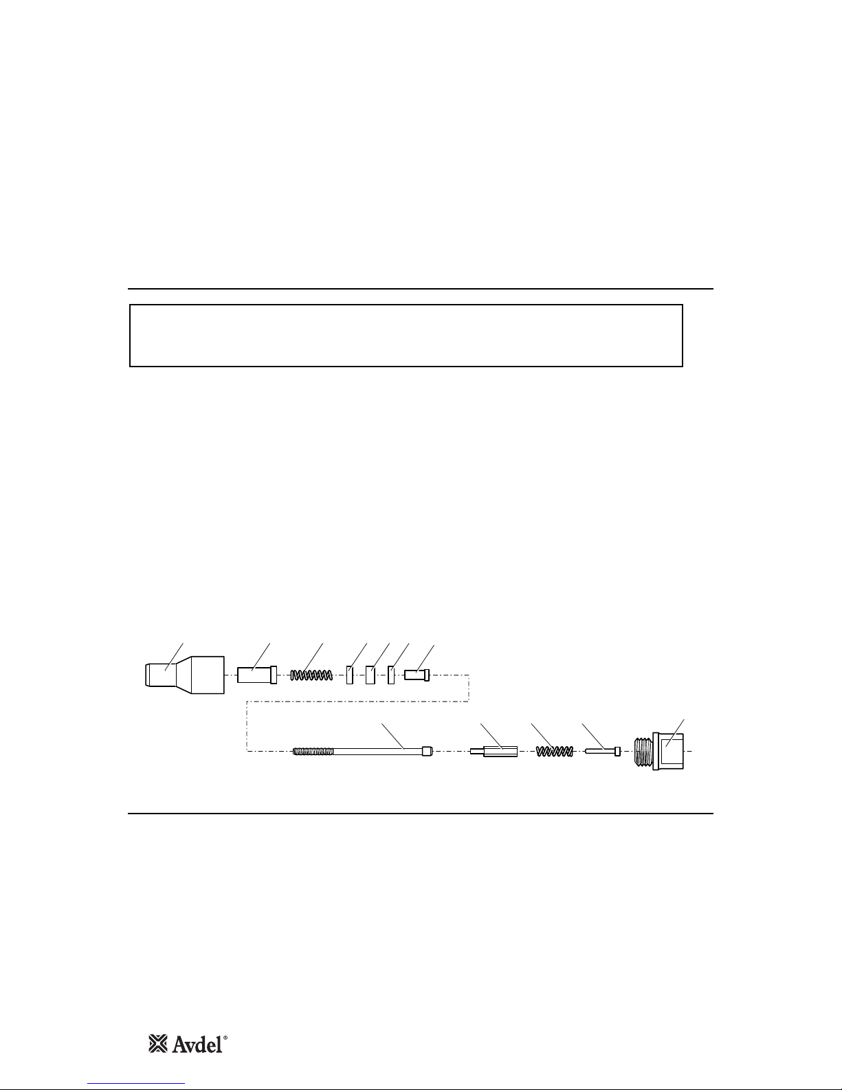
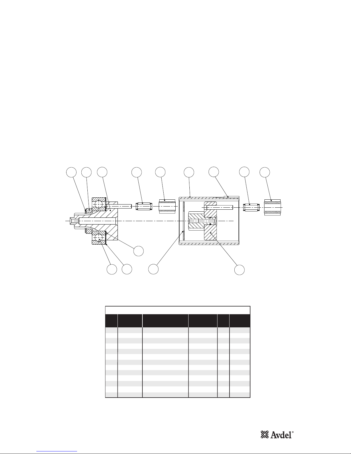
•Where applicable, insert sleeve 8and thrust spring 9into nose housing 2.
•Coat thrust washers 3and thrust bearing 4with high pressure grease (eg. Shell Alvania E.P.I.) and locate them in the order
shown below into the nose housing 2.
•Where applicable, fit spacer 5through thrust washers and thrust bearings.
•Insert drive screw 1through the above assembly.
•Fit drive shaft 6into the hexagon hole in the drive screw head.
•Insert stop 11 and spring 10 into the front of the base tool.
•Screw adaptor 7into clutch housing of the base tool (left hand thread).
•Offer up the nose assembly to the adaptor. It will be necessary to rotate the drive screw by hand to line up the hexagon on
the drive shaft 6with the hexagonal hole in the front jaw of the base tool.
•Screw the nose housing 2onto the adaptor 7and tighten with a spanner (left hand thread).
289
1610
34 3 5
11 7
Nose assemblies should be serviced at weekly intervals.
•Remove the complete nose assembly using the reverse procedure to the ‘Fitting Instructions’.
•Any worn or damaged part should be replaced.
•Particularly check wear on drivescrew, thrust washers and thrust bearing.
•Lubricate thrust washers and thrust bearings with high pressure grease (eg Shell Alvania E.P.I.)
•Check springs are not distorted.
•Assemble according to fitting instructions.

11
Nose Assembly Components
Nose Assemblies
The table below lists all nose assemblies available. Each nose assembly represents a unique assembly of components which
can be ordered individually. Components numbers refer to the text and illustration opposite. We recommend some stock as
items will need regular replacement. Read the nose assemblies servicing instructions opposite carefully. All nose assemblies
also include spring 10 part number 07430-08202 and stop 11 part number 07430-08203.
61 7
NOSE ASSY 243 589
07443-09288 07001-00084 07522-08988 07007-00081 07007-00078 07443-03110 07430-01808 07443-08002 07522-08902 07154-03092
07443-09810 07001-00076 07443-06110 07007-00081 07007-00078 07443-03110 07430-01110 07443-08002 - -
07443-09812 07001-00099 07443-06112 07007-00081 07007-00078 - 07430-01112 07443-08002 - -
07443-09820 07001-00077 07443-06110 07007-00081 07007-00078 07443-03110 07430-01110 07443-08002 - -
07443-09822 07001-00098 07443-06112 07007-00081 07007-00078 - 07430-01112 07443-08002 - -
07443-09840 07001-00078 07443-06110 07007-00081 07007-00078 07443-03110 07430-01110 07443-08002 - -
07443-09842 07001-00106 07443-06112 07007-00081 07007-00078 - 07430-01112 07443-08002 - -
07443-09860 07001-00079 07443-06110 07007-00081 07007-00078 07443-03110 07430-01110 07443-08002 - -
07443-09862 07001-00105 07443-06112 07007-00081 07007-00078 - 07430-01112 07443-08002 - -
07443-09880 07001-00100 07443-06810 07007-00082 07007-00079 - 07430-01810 07443-08003 - -
07443-09888 07001-00084 07443-06110 07007-00081 07007-00078 07443-03110 07430-01808 07443-08002 - -
07443-09910 07001-00076 07443-08805 07007-00081 07007-00078 07443-03110 07430-01110 07443-08002 - -
07443-09920 07001-00077 07443-08805 07007-00081 07007-00078 07443-03110 07430-01110 07443-08002 - -
07443-09940 07001-00078 07443-08805 07007-00081 07007-00078 07443-03110 07430-01110 07443-08002 - -
07443-09960 07001-00079 07443-08805 07007-00081 07007-00078 07443-03110 07430-01110 07443-08002 - -
07443-09988 07001-00084 07443-08805 07007-00081 07007-00078 07443-03110 07430-01808 07443-08002 - -
07528-07085 07001-00256 07557-08985 07007-00080 07007-00077 07521-08808 07521-08806 07443-08001 - --
07552-09548 07001-00336 07552-07704 07007-00080 07007-00077 - 07522-08801 07443-08001 - -
07552-09550 07001-00300 07552-07706 07007-00080 07007-00077 07521-08808 07521-08803 07443-08001 - -
07552-09568 07001-00110 07552-07704 07007-00080 07007-00077 - 07522-08801 07443-08001 - -
07552-09570 07001-00301 07552-07706 07007-00080 07007-00077 07521-08808 07521-08803 07443-08001 - -
07552-09578 07001-00319 07552-07701 07007-00080 07007-00077 07521-08809 07521-08804 07443-08001 - -
07552-09583 07001-00325 07552-07709 07007-00080 07007-00077 07520-08803 07520-08802 07443-08001 - -
07552-09584 07001-00326 07552-07705 07007-00080 07007-00077 07521-08810 07521-08805 07443-08001 - -
07552-09585 07001-00256 07552-07702 07007-00080 07007-00077 07521-08808 07521-08806 07443-08001 - -
07552-09586 07001-00337 07552-07703 07007-00080 07007-00077 - 07522-08802 07443-08001 - -
07552-09588 07001-00084 07552-07710 07007-00081 07007-00078 07443-03110 07430-01808 07443-08002 - -
07556-09184 07001-00326 07552-06804 07007-00080 07007-00077 07521-08810 07521-08805 07443-08001 07552-08804 07440-08002
07556-09185 07001-00256 07552-06805 07007-00080 07007-00077 07521-08808 07521-08806 07443-08001 07552-08805 07440-08002
07556-09186 07001-00337 07552-06806 07007-00080 07007-00077 - 07522-08802 07443-08001 07552-08806 07150-00403
07556-09284 07001-00326 07521-08984 07007-00080 07007-00077 07521-08810 07521-08805 07443-08001 07521-08901 07440-08002
07556-09285 07001-00256 07521-08985 07007-00080 07007-00077 07521-08808 07521-08806 07443-08001 07521-08902 07440-08002
07556-09286 07001-00337 07522-08986 07007-00080 07007-00077 - 07522-08802 07443-08001 07522-08901 07150-00504
07556-09816 07001-00320 07440-06805 07007-00080 07007-00077 07521-08808 07521-08803 07443-08001 - -
07556-09818 07001-00334 07443-06108 07007-00080 07007-00077 - 07522-08801 07443-08001 - -
07556-09828 07001-00333 07443-06108 07007-00080 07007-00077 - 07522-08801 07443-08001 - -
07556-09830 07001-00335 07443-06108 07007-00080 07007-00077 07521-08801 07522-08801 07443-08001 - -
07556-09832 07001-00321 07440-06805 07007-00080 07007-00077 07521-08808 07521-08803 07443-08001 - -
07556-09834 07001-00315 07440-06304 07007-00080 07007-00077 07521-08807 07521-08802 07443-08001 - -
07556-09836 07001-00276 07440-06306 07007-00080 07007-00077 07520-08803 07520-08801 07443-08001 - -
07556-09848 07001-00336 07443-06108 07007-00080 07007-00077 - 07522-08801 07443-08001 - -
07556-09850 07001-00300 07440-06805 07007-00080 07007-00077 07521-08808 07521-08803 07443-08001 - -
07556-09854 07001-00313 07440-06306 07007-00080 07007-00077 07520-08803 07520-08801 07443-08001 - -
07556-09856 07001-00316 07440-06304 07007-00080 07007-00077 07521-08807 07521-08802 07443-08001 - -
07556-09858 07001-00318 07440-06508 07007-00080 07007-00077 07521-08809 07521-08804 07443-08001 - -
07556-09868 07001-00110 07440-06108 07007-00080 07007-00077 - 07522-08801 07443-08001 - -
07556-09870 07001-00301 07440-06805 07007-00080 07007-00077 07521-08808 07521-08803 07443-08001 - -
07556-09876 07001-00317 07440-06304 07007-00080 07007-00077 07521-08807 07521-08802 07443-08001 - -
07556-09878 07001-00319 07440-06508 07007-00080 07007-00077 07521-08809 07521-08804 07443-08001 - -
07556-09883 07001-00325 07440-06308 07007-00080 07007-00077 07520-08803 07520-08802 07443-08001 - -
07556-09884 07001-00326 07440-06508 07007-00080 07007-00077 07521-08810 07521-08805 07443-08001 - -
07556-09885 07001-00256 07440-06805 07007-00080 07007-00077 07521-08808 07521-08806 07443-08001 - -
07556-09886 07001-00337 07443-06108 07007-00080 07007-00077 - 07522-08802 07443-08001 - -
Nose assembly table continued overleaf

12
Nose Assemblies
61 7
NOSE ASSY 243 589
07556-09916 07001-00320 07440-08805 07007-00080 07007-00077 07521-08808 07521-08803 07443-08001 - -
07556-09918 07001-00334 07551-08803 07007-00080 07007-00077 - 07522-08801 07443-08001 - -
07556-09928 07001-00333 07551-08805 07007-00080 07007-00077 - 07522-08801 07443-08001 - -
07556-09930 07001-00335 07551-08802 07007-00080 07007-00077 - 07522-08801 07443-08001 - -
07556-09932 07001-00321 07552-08816 07007-00080 07007-00077 07521-08808 07521-08803 07443-08001 - -
07556-09934 07001-00315 07440-08804 07007-00080 07007-00077 07521-08807 07521-08802 07443-08001 07521-08801 07440-08002
07556-09936 07001-00276 07440-08803 07007-00080 07007-00077 07520-08803 07520-08801 07443-08001 07440-08003 07440-08002
07556-09948 07001-00336 07551-08803 07007-00080 07007-00077 - 07522-08801 07443-08001 - -
07556-09950 07001-00300 07440-08805 07007-00080 07007-00077 07521-08808 07521-08803 07443-08001 - -
07556-09954 07001-00313 07440-08803 07007-00080 07007-00077 07520-08803 07521-08801 07443-08001 - -
07556-09956 07001-00316 07440-08804 07007-00080 07007-00077 07521-08807 07521-08802 07443-08001 - -
07556-09958 07001-00318 07440-08808 07007-00080 07007-00077 07521-08809 07521-08804 07443-08001 - -
07556-09968 07001-00110 07551-08803 07007-00080 07007-00077 - 07522-08801 07443-08001 - -
07556-09970 07001-00301 07440-08805 07007-00080 07007-00077 07521-08808 07521-08803 07443-08001 - -
07556-09974 07001-00314 07440-08803 07007-00080 07007-00077 07520-08803 07520-08801 07443-08001 - -
07556-09976 07001-00317 07440-08804 07007-00080 07007-00077 07521-08807 07521-08802 07443-08001 - -
07556-09978 07001-00319 07440-08808 07007-00080 07007-00077 07521-08809 07521-08804 07443-08001 - -
07556-09983 07001-00325 07440-08803 07007-00080 07007-00077 07520-08803 07520-08802 07443-08001 - -
07556-09984 07001-00326 07552-08817 07007-00080 07007-00077 07521-08810 07521-08805 07443-08001 - -
07556-09985 07001-00256 07440-08805 07007-00080 07007-00077 07521-08808 07521-08806 07443-08001 - -
07556-09986 07001-00337 07551-08802 07007-00080 07007-00077 - 07522-08802 07443-08001 - -
07557-09285 07001-00256 07557-08901 07007-00080 07007-00077 07521-08808 07521-08806 07443-08001 07557-08902 07440-08002

13
Daily Servicing
Weekly Servicing
Servicing the Tool
IMPORTANT
The employer is responsible for ensuring that tool maintenance instructions are given to the appropriate
personnel. The operator should not be involved in maintenance or repair of the tool unless properly trained.
Regular servicing should be carried out and a comprehensive inspection performed annually or every 200000 cycles,
whichever is soonest.
•Daily, before use or when first putting the tool into service, pour a few drops of clean, light lubricating oil into the air inlet
of the tool if no lubricator is fitted on air supply. If the tool is in continuous use, the air hose should be disconnected from
the main air supply and the tool lubricated every two to three hours.
•Check for air leaks. If damaged, hoses and couplings should be replaced by new items.
•If there is no filter on the pressure regulator, bleed the air line to clear it of accumulated dirt or water before connecting
the air hose to the tool. If there is a filter fitted, drain it.
•Check that the nose assembly is correct.
•Inspect the drivescrew in the nose assembly for wear or damage. If there is any, renew.
•Fully dismantle and service the nose assembly (see instructions page 10).
•Lubricate the clutch spring with high pressure grease (eg. Shell Alvania EPI).
•Check the clutch torque setting (see clutch adjustment procedure page 15).
•Check for air leaks in the air supply hose and fittings.

14
Moly-Lithium Grease EP 3753 Safety Data
Safety Data (Grease)
First Aid
SKIN:
As the grease is completely water resistant it is best removed with an approved emulsifying skin cleaner.
INGESTION:
Ensure the individual drinks 30ml Milk of Magnesia, preferably in a cup of milk.
EYES:
Irritant but not harmful. Irrigate with water and seek medical attention.
Fire
FLASH POINT: Above 220°C.
Not classified as flammable.
Suitable extinguishing media: CO2, Halon or water spray if applied by an experienced operator.
Environment
Scrape up for burning or disposal on approved site.
Handling
Use barrier cream or oil resistant gloves.
Storage
Away from heat and oxidising agent.
For lubricating internal tool parts other than those described previously, use Moly-Lithium Grease EP3753 (part number 07992-00020)
15
Maintenance
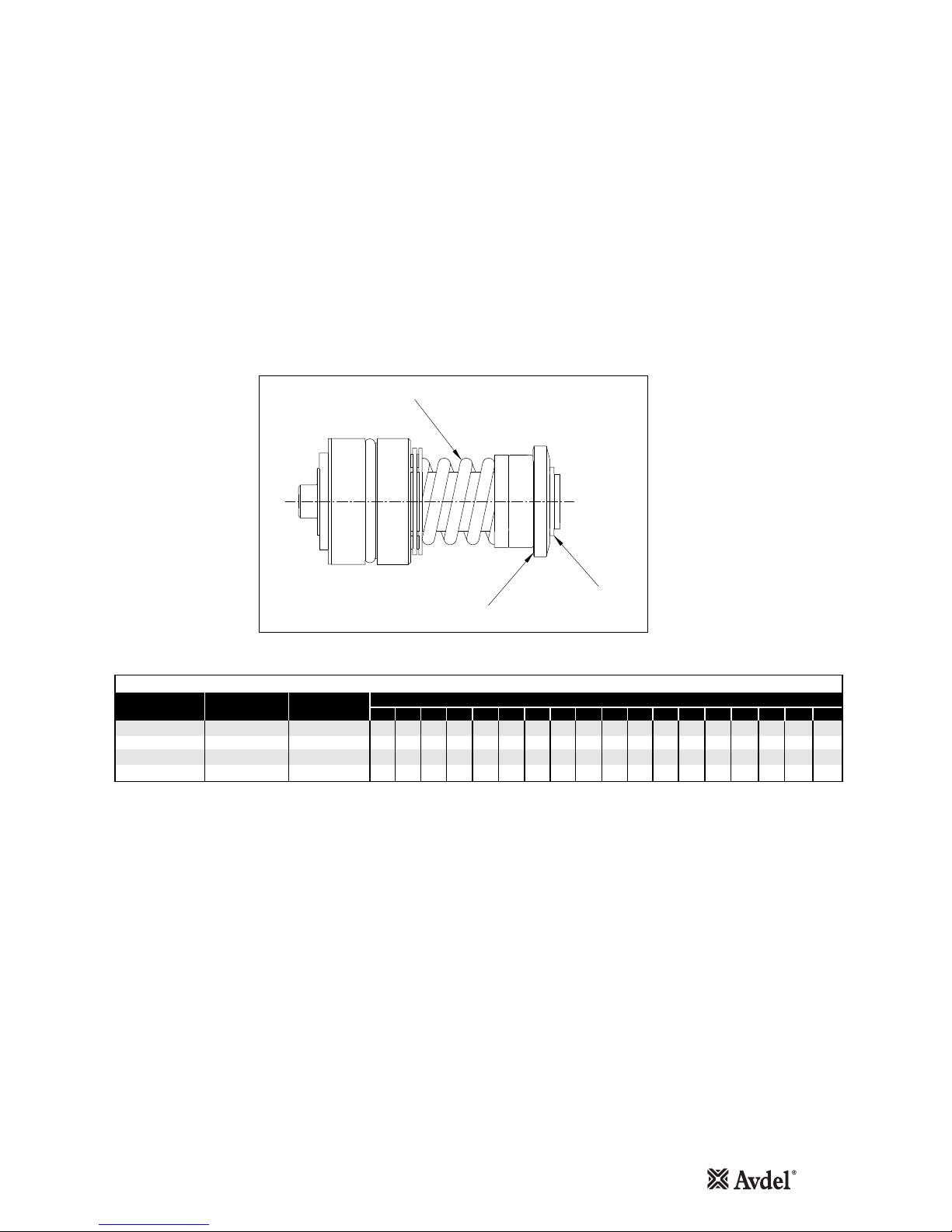
TO RESET CLUTCH TORQUE
•Ensure the correct coloured Clutch Spring is selected in order to obtain the required torque.
•With a minimum gap set between Adjusting Ring 71 and Circlip 72 and using the Clutch Key, rotate 71 (anti clockwise)
until the required number of full turns have been completed to obtain the required Torque as shown in the Table below.
•White numbers on black background indicate Number of turns. Black numbers on white background indicate expected
Torque in 1bf ins.
74110 CLUTCH DETAILS
SPRING
PART Nº
SPRING
COLOUR
1234567891011121314
Nº OF TURNS/lb f ins
UNSET CLUTCH
PART Nº
30 33 38 45 50 56 61 64 - - - - - -
-20 23 24 25 28 30 32 32 36 40 40 42 -
- 9 10 10 14 15 15 15 16 17 18 19 20
------------24
15 16 17 18
----
----
----
5778
84110-15000 84110-15001 BLUE
84100-15000 84100-15001 GREEN
84100-15010 84100-15011 RED
84100-15020 84100-15021 YELLOW
ADJUSTING RING 71
CIRCLIP 72
CLUTCH SPRING

16
Clutch Assembly
Maintenance
CLUTCH ASSEMBLY PARTS LIST
AVDEL
PART No.
SUPPLIER
PART No.
REC
SPARES
ITEM DESCRIPTION QTY
1 296693 CAMCLUTCH 84100-12074 1
2 296623 LATCH PIN 84100-12075 1
7 296683 RETAINING SLEEVE 84100-12076 1
36 37233 O RING 84100-12077 1 2
40 81243 BALL (5mm) 84100-12078 6 6
43 296673 CUP BALL 84100-12079 1
56 68448 SPRING (GREEN) 84100-15001 1
57 71378 SPRING (YELLOW) 84110-15021 1
69 73318 SPRING (BLUE) 84100-15000 1
70 76013 LOCKWASHER 84100-12084 1
71 76003 ADJUSTING RING 84100-12085 1
72 218453 CIRCLIP 84100-12086 1 1
73 72228 BALL 84100-12087 3 2
84 389833 SPACER 84100-12088 1
93 296983 SPINDLE CLUTCH ASSy 84100-12091 1
94 297973 THRUST WASHER 84100-12090 1
95 297963 THRUST RACE 84100-12089 1 1
97 18243 ROLLER 84100-12092 1 2
98 307123 SPRING 84100-12093 1
99 72408 STEEL BALL 84100-12094 14 14
110 389813 COMPLETE CLUTCH 84110-12078 1
DISMANTLING
Item numbers in Bold refer to illustration.
•Unscrew Clutch Case 103 (L/H thread ).
•Remove Bit Holder and Spring Washers.
•Remove Clutch Assy 110.
•Using the supplied Clutch Key rotate Adjusting Ring 71 till a minimum gap between 71 and Circlip 72 is obtained.
•Using suitable Circlip Pliers remove 72.
•Remove Adjusting Ring 71, and Items 70,73,84.
•Remove Clutch Spring 56, 57 or 69.
•Assemble in reverse order, ensuring that Clutch Case 103 is tightened to the correct Torque (6.8Nm) as shown on
assembly drawing 74110-12000 (s).
12736 40 43 56 57 69 7170
99 98 97 95 94 93 84 73 72
110
17
Gearbox Assembly
Maintenance
Item numbers in Bold refer to illustration.
•Thoroughly clean all components.
•Assemble Washers 61 and 62, Distance Collar 92 and Bearing 67, onto Final Planet Carrier 68, retain with Circlip 91.
•Apply recommended grease to all components and assemble into Gear Ring 64.
•With Key 59 in position slide Gear Case 60 over Bearing 67, and insert into Pistol Grip Body.
•Tighten 60 to stated torque value.
•Dismantle in reverse order.
GEARBOX PARTS LIST
AVDEL
PART No.
SUPPLIER
PART No.
REC
SPARES
ITEM DESCRIPTION QTY
59 251993 SQUARE KEY 84110-12048 1
61 500813 WASHER 84110-12050 1
62 500763 WASHER 84110-12051 1
63 251583 WASHER 84110-12052 1
64 251473 GEAR RING 84110-12053 1
65 251663 CAGED NEEDLE ASSy 84110-12054 3 3
67 251983 BEARING 84100-12015 1 1
68 272783 FINAL PLANET CARRIER 84110-12056 1
91 42353 CIRCLIP 84110-12013 1 1
92 157513 DISTANCE COLLAR 84110-12073 1
111 251953 PLANET CARRIER SA 84110-12079 1
113 251673 CAGED NEEDLE ASSy 84110-12080 3 3
114 251403 PLANET WHEEL 84110-12081 3
91
62
6361
67
68
92
111
64 59 113
76
65 114

18
Motor Assembly
Maintenance
Item numbers in Bold refer to illustration.
•Fit Rear Bearing Plate 48 over rear spigot of Rotor 50, applying pressure to inner race of Bearing 47 press to give gap
shown in illustration.
•Fit Rotor Blades 51 (5 off) to Rotor 50, slide Cylinder 49 over the assembly.
•Fit Front Bearing Plate 52 over front spigot of 50. Supporting rear spigot of 50 apply pressure to the inner race of
Bearing 54, press onto front spigot.
•Fit Rear Bearing Housing 46 to rear of assembly.
•Fit Front Bearing Housing 53 to front of assembly.
WARNING
WHEN ASSEMBLING OR SERVICING OIL FREE MOTOR SMOKING IS PROHIBITED. THE
ROTOR BLADES CONTAIN P.T.F.E. AND AT TEMPERATURES ABOVE 300° INHALING THE
RESULTANT VAPOUR MAY CAUSE A TEMPORARY ALLERGIC REACTION. CARE SHOULD BE
TAKEN WHEN BLOWING OUT P.T.F.E. RESIDUE FROM SINTERED SILENCER. ALWAYS WASH
HANDS BEFORE TOUCHING CIGARETTES, PIPES, FOOD ETC.
POSITION OF BLADE
NOTCH UNIMPORTANT
MAXIMUM DIMENSION AFTER BEARING
IS PRESSED ONTO ROTOR
0.040
0.025
45
117 54 53 52 49 51 50 48 4746
MOTOR ASSEMBLY PARTS LIST
AVDEL
PART No.
SUPPLIER
PART No.
REC
SPARES
ITEM DESCRIPTION QTY
45 305743 MOTOR COMPLETE 84110-12036 1
46 256713 REAR BEARING HOUSING 84110-12037 1
47 500693 BEARING 84110-12038 1 2
48 256723 REAR BEARING PLATE 84110-12039 1 1
49 500203 CYLINDER 84110-12040 1
50 251763 ROTOR 84110-12041 1
51 305233 ROTOR BLADES 84110-12042 5 10
52 256733 FRONT BEARING PLATE 84110-12043 1 1
53 256743 FRONT BEARING HOUSING 84110-12044 1
54 64368 BEARING 84110-12045 1 2
117 251393 ROTOR PINION 84110-12082 1
19
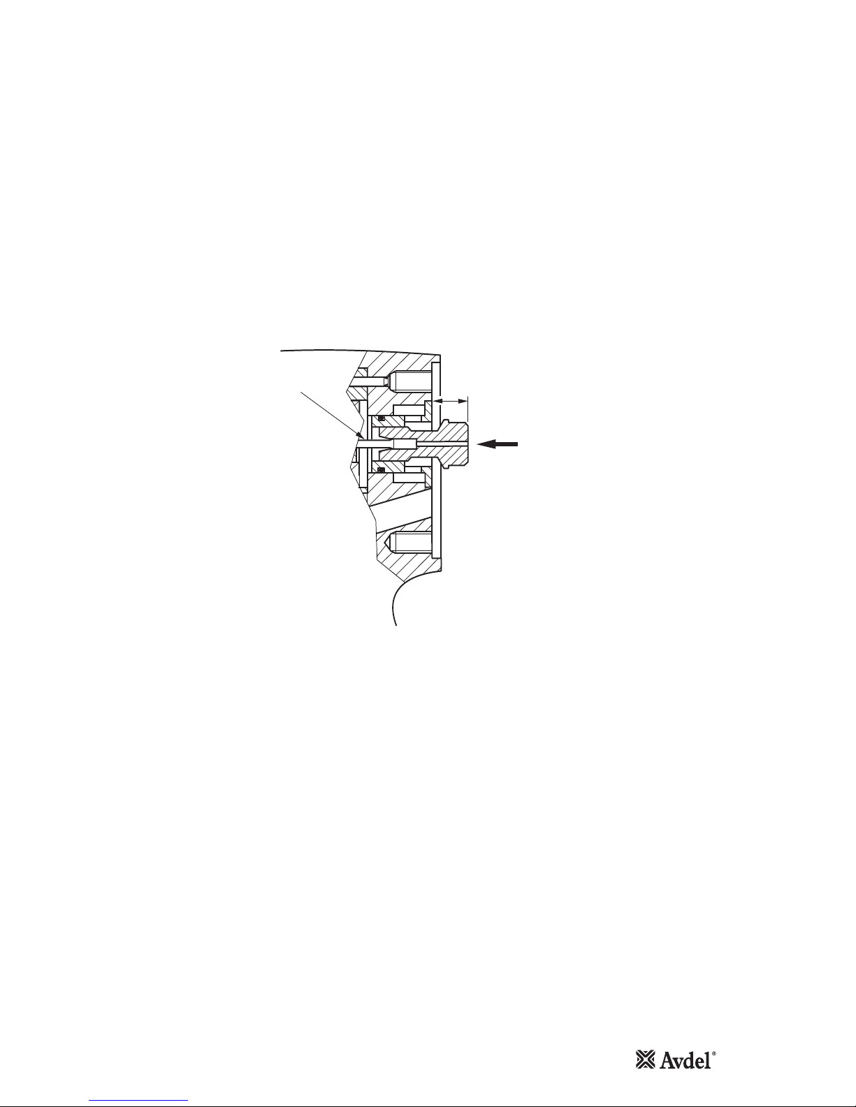
Setting the Push Rod
Maintenance
•Apply shims and spacers to obtain a maximum axial clutch movement of 0.13mm
Note: Shims must be adjacent to face of Bit Holder
•Apply pressure in direction of arrow (A)
•Apply pressure to Push Rod (B) until a hard stop is felt. Measure dimension X.
•Obtain the specified dimension by grinding the Push Rod (B).
X
B
A
7.0 mm
7.2

20
General Assembly of Base Tool 74110-12000(s)
102 103 104 106 67 68 76 65 59 58 55 45 33 79 7874114113111 80 81 85 8682
8
9
63
5
12
4
10
38
37
39
25
23
21
19
41
42
20 18
17 19
15 16
26
14
606361
629291108107
121
96 110 117
13
This manual suits for next models
2
Table of contents
Other Avdel Power Tools manuals


