HID iCLASS SE Express R10 User manual
INSTALLATION GUIDE
iCLASS SE® Express R10 Reader
13.56 MHz / 2.4 GHz Contactless
PLT-03681, Rev. A.2
This Installation Guide is for informational purposes only. HID makes no warranties, expressed or implied, in this summary. Company, product names and data used in sample output
are fictitious. Specifications are subject to change without notice.
© 2018 HID Global Corporation/ASSA ABLOY AB. All rights reserved. This document may not be reproduced, disseminated or republished in any form without the prior written
permission of HID Global Corporation. HID GLOBAL, HID, the HID Brick logo, the Chain Design, HID Reader Manager, HID Mobile Access, and iCLASS SE are trademarks or registered
trademarks of HID Global, ASSA ABLOY AB, or its aliate(s) in the US and other countries and may not be used without permission. All other trademarks, service marks, and
product or service names are trademarks or registered trademarks of their respective owners.
hidglobal.com An ASSA ABLOY Group brand
Supplied parts
iCLASS SE Express R10 Reader (1)
Installation Guide (1)
0.138-20 x 1.5" self tapping screws (2) – for installing
the reader directly to a wall
0.138-32 x 0.375" screws (3) – for mounting to an
enclosure with Imperial (US) threads (2) and attaching
the reader to the back plate (1)
M3.5 x 12mm screws (2) – for mounting to an enclosure
with Metric (EU etc) threads
0.138-32 x 0.375" security screw (1) – alternative
security screw for attaching the reader to the back
plate
Recommended parts (not supplied)
Cable, 5-9 conductor (Wiegand or Clock-and-Data)
Certified LPS DC power supply
Security tool HID 04-0001-03 (for anti-tamper screw)
Drill with various bits for mounting hardware
Mounting hardware
Reader spacer (PN: 6132AKB) when mounting on or
near metal or metal junction boxes - see How to Order
Guide
IP65 Mounting gasket (PN: IP65GSKT-R10, 10 pcs per
kit), recommended for outdoor installation
Specifications
INPUT VOLTAGE (VDC) 12 VDC
CURRENT
STANDBY AVG146 mA
MAX AVG260 mA
PEAK3250 mA
OPERATING TEMPERATURE -30° F to 150° F (-35° C to 66° C)
CABLE LENGTH4Communication Lines (Wiegand)
22 AWG: 500 ft (152 m)
REGULATORY REF NUMBER R10FKNN
FREQUENCY BLE: 2.4 - 2.480 GHz
HF: 13.56 MHz
FCC & IC IDS FCC-ID: JQ6-iCLASSR10F
IC-ID: 2236B-ICLASSR10F
1Standby AVG - RMS current draw without a card in the RF field.
2Maximum AVG - RMS current draw during continuous card reads. Not evaluated by UL.
3Peak - highest instantaneous current draw during RF communication.
4Wiegand Cable Lengths: 500 ft (152 m) 22 AWG @ STANDBY AVG 46 mA, MAX AVG 62.5 mA, PEAK 250 mA
Optional Features
Optical Tamper enabled by default – Once activated, when the mounting plate is removed, the optical tamper will
open the circuit between Tamper#1 and Tamper#2 reader control lines. Tamper#1 and Tamper#2 control lines are
interchangeable. Either of these lines can be connected with the reader ground line to reduce the number of cable cores
required in the reader cable. Tamper#1 and Tamper#2 are rated 0-12VDC at 100mA.
Configuration Cards – The reader can be modified to meet the specific requirements of an installation. Configuration
options include; audio visual, and CSN outputs. See the HID Reader Manager™ solution on www.hidglobal.com for further
details.

November 2018
iCLASS SE® Express R10 Installation Guide
PLT-03681, Rev. A.22
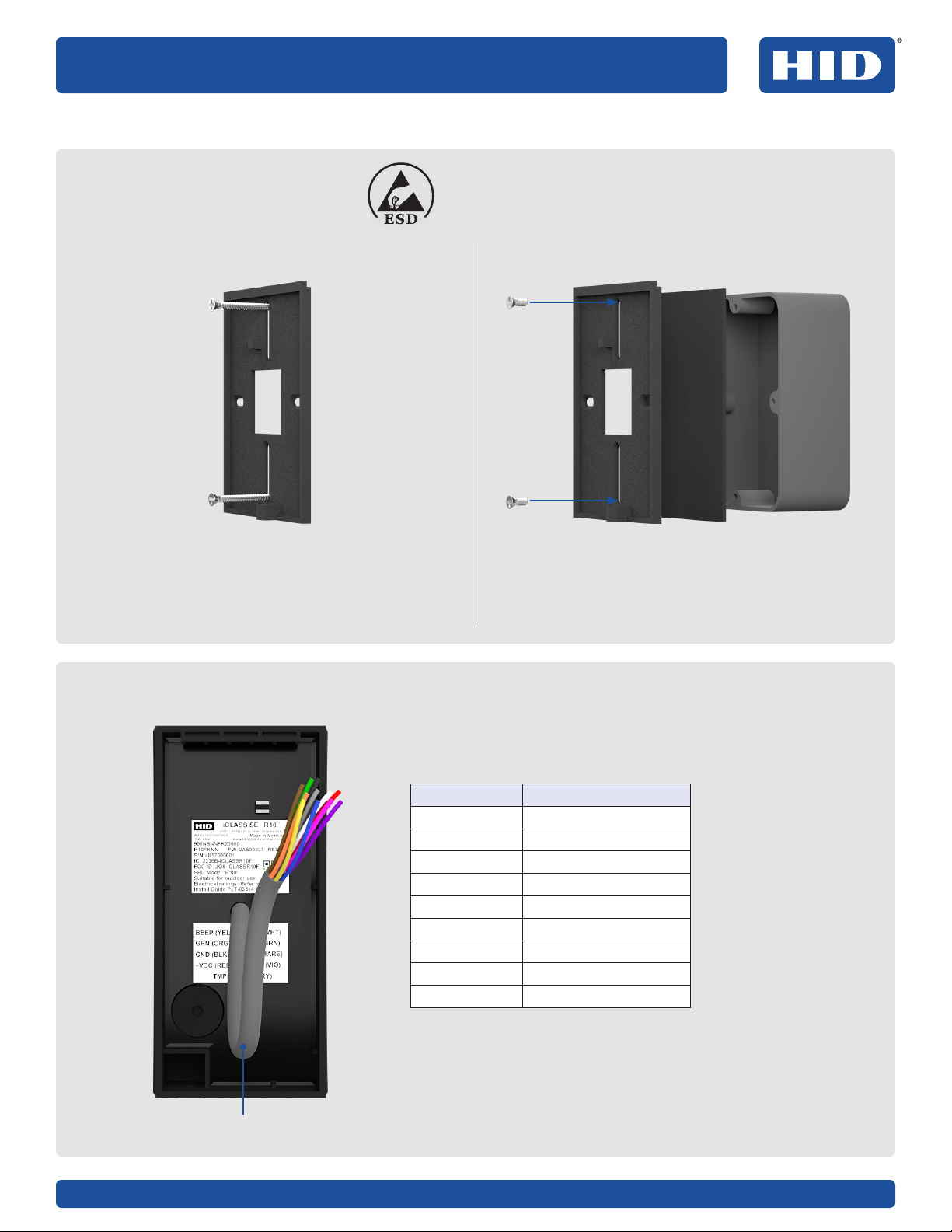
Installation
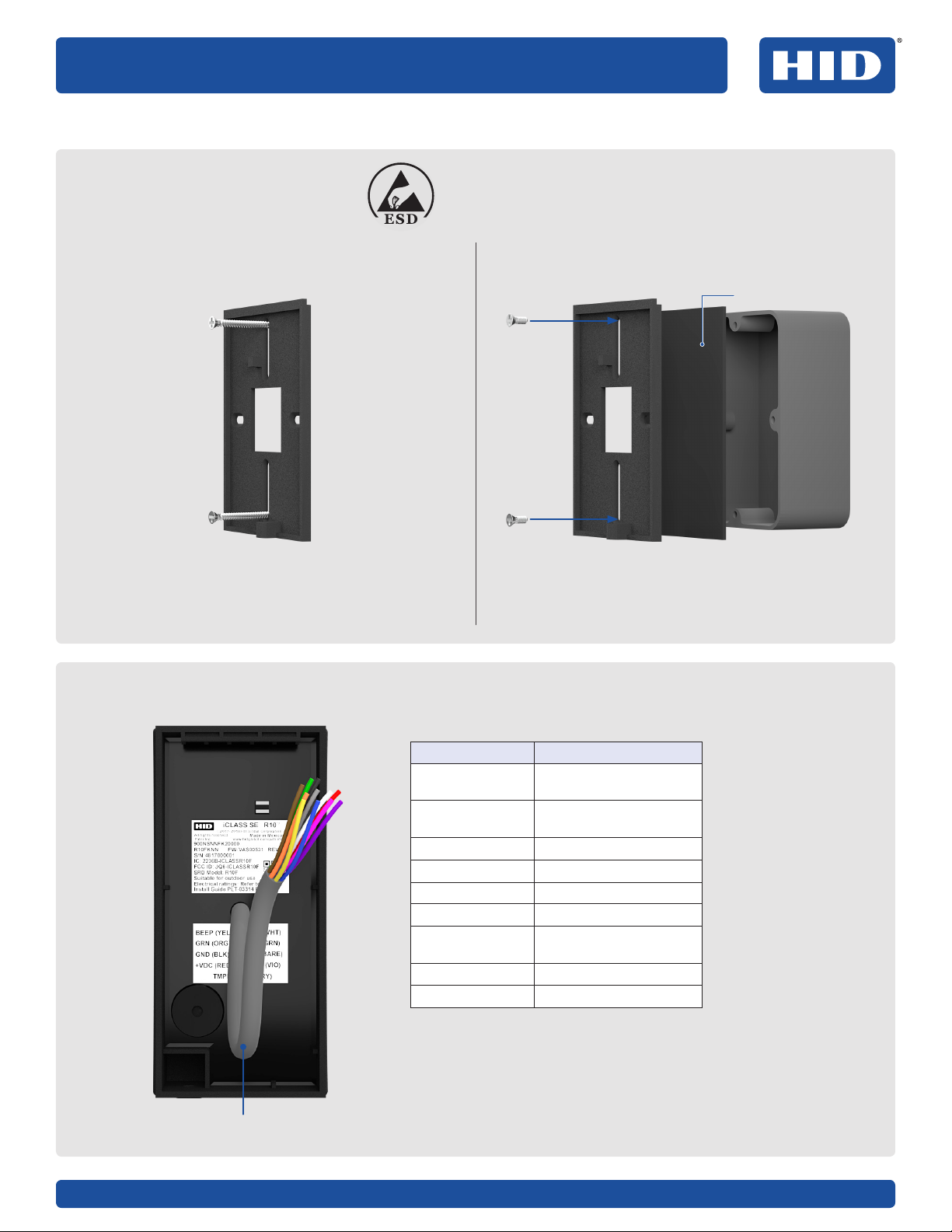
1. Mount the backplate
2. Wire the reader
ATTENTION
Observe precautions for handling
ELECTROSTATIC SENSITIVE DEVICES
Mounting directly to the wall/mullion mount
Use supplied 0.138-20 x 1.5" screws For Imperial (US):
Use supplied 0.138-32 x 0.375" screws
For Metric (EU etc):
Use supplied M3.5 x 12mm screws
Mounting to an enclosure (not supplied)
11
22
PIGTAIL DESCRIPTION
Yellow Beeper Input
Orange LED Input (GRN)
Black Ground (GRN)
Red +VDC
Drain Unused
Violet *Tamper #1
Violet/White *Tamper #2
White Wiegand Data 1
Green Wiegand Data 0
* Tamper Output. When activated or when the reader is
unpowered, the circuit between Tamper#1 and Tamper#2
reader control lines will open.
Note: Wiring the reader incorrectly may permanently
damage the reader.
9 in
(0.23m)
Optional gasket

November 2018
iCLASS SE® Express R10 Installation Guide
PLT-03681, Rev. A.23
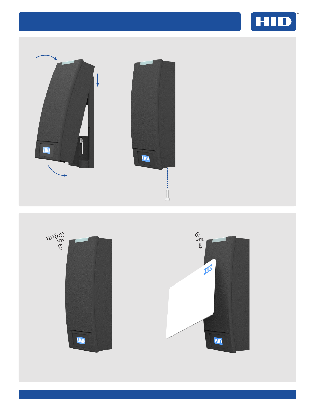
3. Secure the reader to the backplate
4. Power and test the reader
1. Align the top of the reader with the
top of the backplate.
2. Hook the top of the reader on the
top of the backplate.
3. Align the bottom of reader with the
bottom of the backplate.
4. Secure the reader to the backplate
using one of the supplied screws:
Security/non-tamper screw:
0.138-32 x 0.375" screw (supplied)
Non-security/standard screw:
0.138-32 x 0.375" screw (supplied)
Turn on the power. The reader should
beep and the light bar should flash.
Test the reader with a card. The buzzer should
beep and the LED should flash.
1
2
34
Lecteur iCLASS SE® Express R10
13,56MHz/2,4GHz Contactless
PLT-03681, Rev. A.2
Ce guide d'installation est fourni à titre purement informatif. HID exclut toute garantie expresse ou implicite dans cette présentation. Les noms de sociétés, produits et données
apparaissant dans les exemples sont entièrement fictifs. Ces spécifications peuvent être modifiées sans préavis.
©2018 HID Global Corporation/ASSA ABLOY AB. Tous droits réservés. Ce document ne peut être reproduit, diusé ou republié sous aucune forme que ce soit sans l'autorisation
écritepréalable de HID Global Corporation. HID GLOBAL, HID, le logo HID Brick, le design Chain, HID Reader Manager, HID Mobile Access et iCLASS SE sont des marques commerciales
ou des marques déposées de HIDGlobal, d'ASSAABLOYAB ou de leurs filiales aux États-Unis et/ou dans d'autres pays et ne peuvent pas être utilisées sans autorisation. Toutes les
autres marques commerciales ou marques de service et tous les noms de produit ou de service mentionnés dans le présent document sont la propriété de leur détenteur respectif.
hidglobal.com Une marque du groupe ASSA ABLOY
GUIDE D'INSTALLATION
Pièces fournies
Lecteur iCLASS SE Express R10 (1)
Guide d’installation (1)
Vis autotaraudeuses 0,138-20 x 1,5” (2) – pour installer
le lecteur directement sur un mur
Vis 0,138-32 x 0,375” (3) – pour l’installation dans un
caisson à filetages impériaux (États-Unis) (2) et la
fixation du lecteur à la plaque arrière (1)
Vis M3,5 x 12mm (2) – pour l’installation dans un
caisson à filetages métriques (UE, etc.)
Vis de sécurité 0,138-32 x 0,375” (1) – vis de sécurité
alternative pour fixer le lecteur à la plaque arrière
Pièces recommandées (non fournies)
Câble, conducteur 5-9 (Wiegand ou Clock-and-Data)
Alimentation CC certifiée LPS
Outil de sécurité HID 04-0001-03 (pour vis anti-vol)
Perceuse avec diérentes mèches pour matériel de
montage
Matériel de montage
Pièce d’espacement (réf: 6132AKB) pour le montage
sur ou à proximité de métal ou de boîtiers de
raccordement en métal - voir le Guide des commandes
Support d’assemblage IP65 (réf: IP65GSKT-R10, 10pcs
par kit) recommandé pour une installation en extérieur
Spécifications
TENSION D'ENTRÉE (VCC) 12VCC
COURANT
MOY VEILLE146mA
MOY MAX.260mA
CRÊTE3250mA
TEMPÉRATURE DE
FONCTIONNEMENT -35 à 66°C (-30 à 150°F)
LONGUEUR DE CÂBLE4Lignes de communication (Wiegand)
22AWG: 152m (500pi)
NUMÉRO DE RÉF. RÉGLEMENTAIRE R10FKNN
FRÉQUENCE BLE: 2,4 - 2,480GHz
HF: 13,56MHz
ID FCC ET IC ID FCC: JQ6-iCLASSR10F
ID IC: 2236B-ICLASSR10F
1MOY veille: courant ecace sans carte dans le champ RF.
2MOY max.: courant ecace durant les lectures de carte continues. Non évalué par UL.
3Crête: courant instantané le plus élevé durant une communication RF.
4Longueurs de câbles Wiegand: 152m (500pi) 22AWG @ MOY VEILLE 46mA, MOY MAX 62,5mA, CRÊTE 250mA
Fonctionnalités en option
Sécurité optique activée par défaut – Une fois activée, lorsque la plaque de montage est retirée, la sécurité optique ouvrira le
circuit entre les lignes de contrôle du lecteur Sécurité#1 et Sécurité#2. Les lignes de contrôle Sécurité#1 et Sécurité#2 ne sont
pas interchangeables. Ces lignes peuvent être connectées à la ligne au sol du lecteur pour réduire le nombre de conducteurs
de câble nécessaires dans le câble du lecteur. Sécurité#1 et Sécurité#2 ont une tension nominale de 0-12V CC à 100mA.
Cartes de configuration – Le lecteur peut être modifié afin de respecter les exigences spécifiques d'une installation.
Lesoptions de configuration incluent: audiovisuel et sorties CSN. Découvrez la solution HID Reader Manager™ sur
www.hidglobal.com pour plus de détails.
November 2018
iCLASS SE® Express R10: Guide d’installation
PLT-03681, Rev. A.25
Installation
1. Montage de la
plaque arrière
2. Câblage du lecteur
ATTENTION
Les manipulations des APPAREILS SENSIBLES AUX DÉCHARGES
ÉLECTROSTATIQUES doivent être eectuées avec précaution.
Montage direct sur un mur/montant
Utilisez les vis 0,138-20 x 1,5" fournies Pour le système impérial (États-Unis):
Utiliser les vis 0,138-32 x 0,375” fournies
Pour le système métrique (UE, etc.):
Utiliser les vis M3,5 x 12mm fournies
Installation dans un caisson (non fourni)
11
22
PIGTAIL DESCRIPTION
Jaune Entrée bip
Orange Entrée LED (VERT)
Noir Masse (VERT)
Rouge +VCC
Drain Non utilisé
Violet *Sécurité #1
Violet/Blanc *Sécurité #2
Blanc Données Wiegand 1
Vert Données Wiegand 0
*Sortie sécurité. Quand la sortie sécurité est activée ouquand
le lecteur est hors tension, le circuit entre les lignes de
contrôle du lecteur Sécurité#1 et Sécurité#2 s'ouvre.
Remarque: Le câblage incorrect du lecteur peut entraîner
desdommages permanents.
0,23m
(9po)

November 2018
iCLASS SE® Express R10: Guide d’installation
PLT-03681, Rev. A.26
3. Fixation du lecteur à la plaque arrière
4. Mise sous tension et essai du lecteur
1. Alignez le haut du lecteur avec
lehaut de la plaque arrière.
2. Accrochez le haut du lecteur
aveclehaut de la plaque arrière.
3. Alignez le bas du lecteur avec
lebasde la plaque arrière.
4. Fixez le lecteur à la plaque arrière
enutilisant l'une des vis fournies:
Vis de sécurité/inviolable:
Vis 0,138-32 x 0,375” (fournies)
Vis sans sécurité/standard:
Vis 0,138-32 x 0,375” (fournies)
Allumez l'appareil. Le lecteur
doitémettre un bip, et la barre
lumineuse doit clignoter.
Testez le lecteur avec une carte. Le buzzer
doit émettre un bip et la LED doit clignoter.
1
2
34
iCLASS SE® Express R10 Leser
13,56MHz/2,4GHz kontaktlos
PLT-03681, Rev. A.2
Diese Installationsanleitung dient nur zu Informationszwecken. HID übernimmt keine Garantien, weder ausdrücklich noch implizit, in Bezug auf diese Zusammenfassung.
DieindenBeispielausgaben verwendeten Unternehmen, Produktnamen und Daten sind frei erfunden. Änderungen an den Spezifikationen sind vorbehalten.
© 2018 HID Global Corporation/ASSA ABLOY AB. Alle Rechte vorbehalten. Dieses Dokument darf ohne vorherige schriftliche Erlaubnis der HID Global Corporation in keiner Weise
vervielfältigt, verbreitet oder neu veröentlicht werden. HID GLOBAL, HID, das HID Brick-Logo, das Chain Design, HID Reader Manager, HID Mobile Access und iCLASS SE sind
Marken oder eingetragene Marken von HID Global, ASSA ABLOY AB oder verbundener Unternehmen in den USA und/oder anderen Ländern und dürfen ohne Genehmigung nicht
verwendet werden. Alle anderen Marken, Dienstleistungsmarken und Produkt- oder Dienstleistungsnamen sind Marken oder eingetragene Marken ihrer jeweiligen Inhaber.
hidglobal.com Eine Marke der ASSA ABLOY Group
INSTALLATIONSANLEITUNG
Lieferumfang
iCLASS SE Express R10 Leser (1)
Installationsanleitung (1)
0,138–20×1,5-Zoll-Schneidschrauben (2)– zur
Installation des Lesers direkt an der Wand
0,138–32×0,375-Zoll-Schrauben (3)– für Montage
an einem Gehäuse mit britischen Gewinden (2) und
Befestigung des Lesers an der Rückplatte (1)
M3,5×12-mm-Schrauben (2)– für Montage an einem
Gehäuse mit metrischen Gewinden (EU usw.)
0,138–32×0,375-Zoll-Sicherungsschraube (1)–
alternative Sicherungsschraube zur Befestigung des
Lesers an der Rückplatte
Empfohlene Teile
(nichtimLieferumfang enthalten)
Kabel, 5–9Leiter (Wiegand oder Clock-&-Data)
Zertifiziertes LPS DC-Netzteil
Sicherheitswerkzeug HID 04-0001-03 (für
manipulationssichere Schraube)
Bohrer mit verschiedenen Bits für Befestigungsmaterial
Befestigungsmaterial
Leser-Distanzstück (TN: 6132AKB) für Montage auf
oder nahe Metall oder Anschlussdosen aus Metall–
siehe Bestellhandbuch
IP65-Montagedichtung (TN: IP65GSKT-R10, 10St. pro
Satz) für die Montage im Freien empfohlen
Spezifikationen
EINGANGSSPANNUNG (VDC) 12VDC
STROMSTÄRKE
STANDBY AVG146mA
MAX AVG260mA
PEAK3250mA
BETRIEBSTEMPERATUR -30 bis 150°F (-35 bis 66°C)
KABELLÄNGE4Kommunikationsleitungen (Wiegand)
22AWG: 500ft (152m)
BEHÖRDLICHE REF.NUMMER R10FKNN
FREQUENZ BLE: 2,4–2,480GHz
HF: 13,56MHz
FCC-ID & IC-ID FCC-ID: JQ6-iCLASSR10F
IC-ID: 2236B-ICLASSR10F
1Standby AVG– Eektive Stromaufnahme ohne Karte im RF-Feld.
2Maximum AVG– Eektive Stromaufnahme beim dauernden Kartenlesen. Nicht von UL bewertet.
3Peak– Höchste verzögerungsfreie Stromaufnahme während RF-Kommunikation.
4 Wiegand-Kabellängen: 500ft (152m) 22AWG @ STANDBY AVG 46mA, MAX AVG 62,5mA, PEAK 250mA
Optionale Features
Optische Verriegelung standardmäßig aktiviert: Einmal aktiviert, önet die optische Verriegelung den Schaltkreis
zwischen den Steuerungsleitungen des Lesers Tamper#1 und Tamper#2, wenn die Montageplatte entfernt wird. Die
Steuerungsleitungen Tamper#1 und Tamper#2 sind austauschbar. Eine beliebige dieser Leitungen kann mit dem Erdleiter
des Lesers verbunden werden, um die Anzahl der im Leserkabel erforderlichen Kabelseelen zu verringern. Tamper#1 und
Tamper#2 sind auf 0–12VDC bei 100mA ausgelegt.
Konfigurationskarten: Der Leser kann an die spezifischen Anforderungen der Installation angepasst werden.
Konfigurationsoptionen umfassen: audiovisuelle und CSN-Ausgänge. Weitere Informationen erhalten Sie in der
HIDReader Manager™ Lösung auf www.hidglobal.com.

November 2018
iCLASS SE® Express R10 Installationsanleitung
PLT-03681, Rev. A.28
Installation
1. Anbringen der
Rückplatte
2. Den Leser verdrahten
ACHTUNG
Beachten Sie die Vorsichtsmaßnahmen für den Umgang
mitELEKTROSTATISCH GEFÄHRDETEN BAUELEMENTEN
Direkt an der Wand/an einem Pfosten
Verwenden Sie die mitgelieferten
0,138–20×1,5-Zoll-Schrauben
Für die Version mit imperialen Maßeinheiten (US):
Verwenden Sie die mitgelieferten
0,138–32×0,375-Zoll-Schrauben
Für die Version mit metrischen Maßeinheiten (EU usw.):
Verwenden Sie die mitgelieferten M3,5×12-mm-Schrauben
Montage an einem Gehäuse
(nicht im Lieferumfang enthalten)
11
22
Optionale Dichtung
ANSCHLUSSLITZE BESCHREIBUNG
Gelb Beeper-Eingang
Orange LED-Eingang (GRN)
Schwarz Erde (GRN)
Rot +VDC
Erdungsleitung Ungenutzt
Violett *Tamper#1
Voilett/Weiß *Tamper#2
Weiß Wiegand-Daten1
Grün Wiegand-Daten0
*Ausgang Verriegelung. Bei Aktivierung oder bei
ausgeschaltetem Leser önet sich der Schaltkreis zwischen
den Steuerungsleitungen des Lesers Tamper#1und Tamper#2.
Hinweis: Eine falsche Verdrahtung kann den Leser dauerhaft
beschädigen.
9Zoll
(0,23m)

November 2018
iCLASS SE® Express R10 Installationsanleitung
PLT-03681, Rev. A.29
3. Den Leser an der Rückplatte befestigen
4. Leser anschalten und prüfen
1. Richten Sie die Oberkante des Lesers
an der Oberkante der Rückplatte aus.
2. Haken Sie die Oberkante des Lesers
an der Oberkante der Rückplatte ein.
3. Richten Sie die Unterkante des
Lesers an der Unterkante der
Rückplatte aus.
4. Befestigen Sie den Leser an der
Rückplatte, indem Sie eine der
mitgelieferten Schrauben verwenden:
Sicherungsschraube/
manipulationssichere Schraube:
0,138–32×0,375-Zoll-Schraube
(imLieferumfang enthalten)
Standardschraube/keine
Sicherungsschraube:
0,138–32×0,375-Zoll-Schraube
(imLieferumfang enthalten)
Schalten Sie den Leser ein.
DerLesersollte piepen, und
dieLichtleiste sollte blinken.
Testen Sie den Leser mit einer Karte.
Essollteein Piepton zu hören sein,
unddieLED sollte blinken.
1
2
34
Lector iCLASS SE® Express R10
13.56 MHz / 2.4 GHz sin contacto
PLT-03681, Rev. A.2
Esta guía de instalación es únicamente para fines informativos. HID no ofrece ninguna garantía expresa o implícita en este resumen. Las empresas, los nombres de productos y los
datos utilizados en la muestra de salida son ficticios. Las especificaciones pueden cambiar sin previo aviso.
© 2018 HID Global Corporation/ASSA ABLOY AB. Todos los derechos reservados. Este documento no puede reproducirse, divulgarse ni reeditarse en forma alguna sin el consentimiento
previo por escrito de HID Global Corporation. HID GLOBAL, HID, el logotipo de HID Brick, el diseño de la cadena, HID Reader Manager, HID Mobile Access y iCLASS SE son marcas
comerciales o marcas comerciales registradas de HID Global, ASSA ABLOY AB o sus empresas subsidiarias en EUA y en otros países, y no pueden usarse sin permiso. Todas las demás
marcas comerciales, marcas de servicio y nombres de productos o servicios son marcas comerciales o marcas comerciales registradas de sus respectivos propietarios.
hidglobal.com Una marca de ASSA ABLOY Group
GUÍA DE INSTALACIÓN
Lista de piezas
Lector iCLASS SE Express R10 (1)
Guía de instalación (1)
2 tornillos autoperforantes 0.138-20 x 1.5": para instalar
el lector directamente a la pared
3 tornillos 0.138-32 x 0.375": para montar en un recinto
con 2 roscas (sistema imperial, EUA) y sujetar el lector
a 1 placa trasera
2 tornillos M3.5 x 12 mm: para instalar en un recinto con
roscas (sistema métrico, UE y otros)
1 tornillo de seguridad 0.138-32 x 0.375": tornillo alterno
de seguridad para sujetar el lector a la placa trasera
Lista de componentes
recomendados (no incluidos)
Cable, 5 a 9 conductores (Wiegand o Clock-and-Data)
Fuente de alimentación de CC con certificación LPS
Herramienta de seguridad HID04-0001-03 (para tornillo
contra sabotaje)
Taladro con varias brocas para tornillería de montaje
Tornillería de montaje
Espaciador del lector (núm. de componente: 6132AKB) por
si se coloca sobre o cerca de cajas metálicas o cajas para
conexiones metálicas. Consulte la guía sobre Cómo realizar
pedidos
Guarnición de montaje IP65 (núm. de componente:
IP65GSKT-R10, 10 piezas por cada kit), recomendada para
instalación en exteriores
Especificaciones
VOLTAJE DE ENTRADA (VCC) 12 VCC
CORRIENTE ELÉCTRICA
PROM. EN MODO DE ESPERA146mA
PROM. MÁX.260mA
MÁX.3250mA
TEMPERATURA DE
FUNCIONAMIENTO -30 a 150°F (-35 a 66°C)
LONGITUD DEL CABLE4Líneas de comunicaciones (Wiegand)
22 AWG: 500 pies (152m)
NÚMERO DE REFERENCIA
REGULATORIO R10FKNN
FRECUENCIA BLE: 2.4-2.480GHz
HF: 13.56 MHz
ID DE FCC E IC ID de FCC: JQ6-iCLASSR10F
ID de IC: 2236B-ICLASSR10F
1 PROM. en modo de espera: consumo de corriente en RMS sin una tarjeta en el campo de RF.
2PROM. máx.: consumo de corriente en RMS durante la lectura continua de tarjetas. No evaluado por UL.
3 MÁX.: consumo máximo de corriente instantánea durante comunicaciones de RF.
4Longitud del cable Wiegand: 500 pies (152 m) 22 AWG @ PROM. EN MODO DE ESPERA 46 mA, PROM. MÁX. 62.5 mA, MÁX 250 mA.
Características opcionales
Interruptor de sabotaje óptico activado de forma predeterminada: una vez accionado, cuando se retira la placa de
montaje, el interruptor de sabotaje óptico abre el circuito entre las líneas de control del lector de los interruptores de
sabotaje n.° 1 y n.°2. Las líneas de control de los interruptores de sabotaje n.°1 y el n.°2 son intercambiables. Cualquiera
de estas líneas se puede conectar a la línea de tierra del lector para reducir el número de cables básicos que requiere el
cable del lector. Los interruptores de sabotaje n.°1 y n.°2 están calificado para funcionar entre 0-12 VCC a 100mA.
Tarjetas de configuración: el lector se puede modificar para cumplir con los requisitos específicos de una instalación.
Lasopciones de configuración incluyen salidas de audio, visuales y CSN. Para mayor información, consulte la solución
deHID Reader Manager™ en www.hidglobal.com.

November 2018
Guía de instalación de iCLASS SE® Express R10
PLT-03681, Rev. A.211
Instalación
1. Instale la placa trasera
2. Conecte los cables del lector
ATENCIÓN
Lea las precauciones antes de manipular DISPOSITIVOS
SENSIBLES A DESCARGAS ELECTROSTÁTICAS
Instalación directa a la pared o columna
Utilice los tornillos 0.138-20 x 1.5" incluidos Para sistema imperial (EUA):
Utilice los tornillos 0.138-32 x 0.375" incluidos
Para sistema métrico (UE y otros):
Utilice los tornillos M3.5 x 12 mm incluidos
Montaje a un recinto (no se incluye)
11
22
Guarnición opcional
FLEXIBLE DESCRIPCIÓN
Amarillo Entrada de bíper
Naranja Entrada para LED (GRN)
Negro Conexión a tierra (GRN)
Rojo +VCC
Drenaje Sin uso
Violeta *Interruptor de sabotaje #1
Violeta/Blanco *Interruptor de sabotaje #2
Blanco Datos Wiegand 1
Verde Datos Wiegand 0
* Salida del interruptor de sabotaje. Cuando se activa ocuando
el lector no tiene energía, se abre el circuito entre las líneas
de control del lector de los interruptores de sabotaje #1 y #2.
Nota: el lector puede sufrir un daño permanente si el cableado
es incorrecto.
9 pulgadas
(0.23 m)

November 2018
Guía de instalación de iCLASS SE® Express R10
PLT-03681, Rev. A.212
3. Asegure el lector a la placa trasera
4. Encienda y pruebe el lector
1. Alinee la parte superior del lector
conla de la placa trasera.
2. Enganche la parte superior del
lectora la placa trasera.
3. Alinee la parte inferior del lector
conla de la placa trasera.
4. Asegure el lector a la placa trasera
con alguno de los tornillos incluidos:
Tornillo de seguridad/contra sabotaje:
Tornillo 0.138-32 x 0.375" (incluido)
Tornillo estándar/no seguro:
Tornillo 0.138-32 x 0.375" (incluido)
Encienda el dispositivo. El lector
debe emitir un sonido y la barra
deluz debe brillar.
Pruebe el lector con una tarjeta. El timbre
debe emitir un sonido y el LED debe brillar.
1
2
34
Считыватель iCLASS SE® Express R10
13,56МГц / 2,4ГГц (без контакта)
PLT-03681, Rev. A.2
Настоящее руководство по установке предназначено для использования исключительно в информационных целях. В этом сводном документе компания HID не предоставляет никаких гарантий, будь то явно выраженные
или подразумеваемые. Наименования предприятия и товаров и сведения, используемые в примере выходных данных, являются вымышленными. Технические характеристики могут быть изменены без уведомления.
©HID Global Corporation/ASSA ABLOY AB., 2018. Все права защищены. Запрещено воспроизведение, распространение или повторная публикация этого документа в какой бы то ни было форме без предварительного
письменного согласия корпорации HID Global. HID GLOBAL, HID, логотип HID Brick, Chain Design, HID Reader Manager, HID Mobile Access иiCLASS SE являются товарными знаками или зарегистрированными
товарными знаками компании HID Global, ASSA ABLOY AB или аффилированных с ней компаний в США и других странах и не могут быть использованы без получения разрешения. Все прочие товарные знаки, знаки
обслуживания и наименования товаров и услуг являются товарными знаками или зарегистрированными товарными знаками соответствующих владельцев.
hidglobal.com Бренд ASSA ABLOY Group
РУКОВОДСТВО ПО УСТАНОВКЕ
Поставляемые компоненты
Считыватель iClass SE Express R10 (1 шт.)
Руководство по установке (1 шт.)
0,138–20 x 1,5-дюймовые самонарезающие винты (2 шт.) —
для крепления считывателя непосредственно к стене
0,138–32 x 0,375-дюймовые винты (3 шт.) — для крепления
к корпусу с помощью резьбовых соединительных элементов
(2 шт.), выполненных по дюймовому стандарту (США), и
монтажа считывателя на заднюю пластину (1 шт.)
M3,5 x 12 мм винты (2 шт.) — для крепления к корпусу
с помощью резьбовых соединительных элементов,
выполненных по метрическому стандарту (ЕС и т. д.)
0,138–32 x 0,375-дюймовые защитные винты (1 шт.) —
альтернативный защитный винт для крепления считывателя к
задней пластине
Рекомендуемые компоненты
(не входят в комплект поставки)
Кабель, 5–9 жил (Wiegand или Clock-and-Data)
Сертифицированный источник питания постоянного тока с
ограниченной мощностью
Ключ для защитного приспособления HID 04-0001-03 (для
защитного винта)
Дрель с различными битами для крепежей
Крепежи
Перегородка считывателя (номер продукта: 6132AKB) —
информацию для установки вблизи металлических элементов
или металлических соединительных коробок или на них см. в
руководстве по оформлению заказа
Установочная прокладка IP65 (номер продукта: IP65GSKT-R10,
10 шт. на комплект), рекомендуется для использования при
наружной установке.
Технические характеристики
ВХОДНОЕ НАПРЯЖЕНИЕ (В ПОСТ. ТОКА)
12В пост. тока
ТОК
СРЕДНИЙ ТОК В РЕЖИМЕ ОЖИДАНИЯ146мА
МАКСИМАЛЬНЫЙ СРЕДНИЙ ТОК260мА
ПИКОВЫЙ ТОК3250мА
РАБОЧАЯ ТЕМПЕРАТУРА от –35 до 66°C (от –30 до 150°F)
ДЛИНА КАБЕЛЯ4Линии связи (Wiegand)
22AWG: 152м(500футов)
НОРМАТИВНЫЙ СПРАВОЧНЫЙ НОМЕР R10FKNN
ЧАСТОТА BLE: 2,4–2,480ГГц
HF: 13,56МГц
ИДЕНТИФИКАЦИОННЫЕ НОМЕРА ФЕДЕРАЛЬНОЙ
КОМИССИИ СВЯЗИ(ФКС) И ИНТЕГРАЛЬНОЙ СХЕМЫ (ИС)Идентификационный номер ФКС: JQ6-iCLASSR10F
Идентификационный номер ИС: 2236B-ICLASSR10F
1Средний ток в режиме ожидания— среднеквадратическое значение потребления тока, когда в ВЧ-поле отсутствует карта.
2Максимальный средний ток — среднеквадратическое значение потребления тока при непрерывном считывании карт. Не оценено лабораторией UL.
3Пиковый ток— наивысшее мгновенное значение потребления тока при передаче данных в высокочастотном поле.
4 Длина кабеля Wiegand: 152м(500футов) 22 AWG; СРЕДНИЙ ТОК В РЕЖИМЕ ОЖИДАНИЯ: 46мА, МАКСИМАЛЬНЫЙ СРЕДНИЙ ТОК: 62,5мА, ПИКОВЫЙ
ТОК: 250мА
Дополнительные функции
Оптический датчик вскрытия, включенный по умолчанию— если после активации оптического датчика будет снята
монтажная плата, оптический датчик вскрытия разомкнет цепь между линиями управления считывателем Tamper#1 и Tamper#2.
Линии управления Tamper#1 и Tamper#2 являются взаимозаменяемыми. Любая из этих линий может быть подключена к цепи
заземления считывателя, что позволит уменьшить количество сердечников жил кабеля, используемых в кабеле считывателя.
Номинальные параметры линий Tamper#1 и Tamper#2: 0–12 В постоянного тока при силе тока 100 мА.
Карты конфигурации— позволяют настроить считыватель для конкретных требований системы, в которую он устанавливается.
Возможные настройки конфигурации: аудио, видео и выходы CSN. Для получения дополнительных сведений изучите
информацию о HID Reader Manager™ на сайте www.hidglobal.com.
November 2018
Руководство по установке iCLASS SE® Express R10
PLT-03681, Rev. A.214
Установка
1. Установите заднюю
пластину
2. Подключите проводку считывателя
ВНИМАНИЕ!
Соблюдайте меры предосторожности, применяемые при использовании
УСТРОЙСТВ, ЧУВСТВИТЕЛЬНЫХ К ЭЛЕКТРОСТАТИЧЕСКОМУ РАЗРЯДУ
Установка непосредственно на стену
или вертикальный импост
Используйте поставляемые в комплекте
0,138–20x1,5-дюймовые болты
Для дюймового стандарта (США):
Используйте поставляемые в комплекте
0,138–32x0,375-дюймовые болты
Для метрического стандарта (ЕС и т. д.):
Используйте поставляемые в комплекте M3,5x12мм болты
Крепление к корпусу
(не входит в комплект поставки)
11
22
Дополнительная прокладка
ГИБКИЙ ВЫВОД ОПИСАНИЕ
Желтый Вход звукового
сигнализатора
Оранжевый Вход светодиодного
индикатора (GRN)
Черный Заземление (GRN)
Красный +В пост. тока
Потребление Не используется
Фиолетовый *Линия Tamper#1
Фиолетовый/
белый
*Линия Tamper#2
Белый Wiegand Data1
Зеленый Wiegand Data0
*Выход датчика вскрытия. После активации оптического
датчика вскрытия (или после обесточивания считывателя)
цепь между линиями управления считывателем Tamper#1
иTamper#2будет разомкнута.
Примечание.Неправильная прокладка проводки может привести
к необратимому повреждению считывателя.
0,23м
(9дюймов)
November 2018
Руководство по установке iCLASS SE® Express R10
PLT-03681, Rev. A.215
3. Надежно соедините считыватель и заднюю пластину
4. Включите питание и проверьте считыватель
1. Совместите верхнюю часть считывателя
с верхней частью задней пластины.
2. Зацепите верхнюю часть считывателя
за верхнюю часть задней пластины.
3. Совместите нижнюю часть считывателя
с нижней частью задней пластины.
4. Надежно прикрепите считыватель
к задней пластине, используя один из
предоставленных в комплекте болтов.
Защитный болт (предотвращающий
вмешательство):
0,138–32x0,375-дюймовый болт
(поставляется в комплекте)
Обычный болт (не предотвращающий
вмешательство):
0,138–32x0,375-дюймовый болт
(поставляется в комплекте)
Включите питание. Считыватель
должен подать звуковой сигнал,
а световой индикатор должен мигнуть.
Проверьте работоспособность считывателя с помощью
карты. Должен раздаться соответствующий звук зуммера,
сопровождаемый миганием светодиодного индикатора.
1
2
34

Leitor iCLASS SE® Express R10
13,56 MHz/2,4 GHz sem contato
PLT-03681, Rev. A.2
Este guia de instalação é meramente informativo. A HID não oferece quaisquer garantias, expressas ou implícitas, neste resumo. Os nomes de empresas, produtos e dados usados
neste material de exemplo são fictícios. As especificações estão sujeitas a alterações sem aviso prévio.
© 2018 HID Global Corporation/ASSA ABLOY AB. Todos os direitos reservados. Este documento não pode ser reproduzido, divulgado ou republicado de qualquer forma sem a permissão
prévia por escrito da HID Global Corporation. HID GLOBAL, HID, o logotipo retangular HID, o design que sugere uma corrente, HID Reader Manager, HID Mobile Access e iCLASS SE são
marcas comerciais ou marcas comerciais registradas da HID Global, ASSA ABLOY AB ou de suas afiliadas nos EUA e/ou em outros países e não podem ser utilizadas sem permissão.
Todas as outras marcas comerciais, marcas de serviços ou nomes de serviços são marcas comerciais ou marcas comerciais registradas de seus respectivos proprietários.
hidglobal.com Uma marca do grupo ASSA ABLOY
GUIA DE INSTALAÇÃO
Fornecido com o produto
Leitor iCLASS SE Express R10 (1)
Guia de instalação (1)
Parafusos 0,138-20 x 1,5" de auto-rosqueamento (2) –
para fixar o leitor diretamente na parede
Parafusos 0,138-32 x 0,375” (3) – dois para instalar o
leitor dentro da caixa de junção Imperial (EUA) e um
para fixá-lo na placa traseira
Parafusos M3.5 x 12 mm (2) – para instalar o leitor na
caixa de junção Metric (UE e outras localidades)
Parafuso de segurança 0,138-32 x 0,375” (1) – parafuso
de segurança sobressalente para fixar o leitor na placa
traseira
Recomendado
(nãofornecidocomoproduto)
Cabo, condutor 5-9 (Wiegand ou Clock-and-Data)
Fonte de alimentação CC com certificação LPS
Ferramenta de segurança HID 04-0001-03 (para o
parafuso antiviolação)
Furadeira com várias brocas para a montagem do
equipamento
Equipamento de montagem
Espaçador (Número de Peça 6132AKB) se o leitor for
instalado em uma caixa de junção de metal ou próximo
a uma – consulte o Guia para pedidos
Junta de montagem IP65 (Número de Peça
IP65GSKT-R10, 10 unidades por kit) para instalação em
ambientes externos
Especificações
VOLTAGEM DE ENTRADA (VCC)
12 VCC
CORRENTE
MÉDIA EM ESPERA146mA
MÉDIA MÁXIMA260mA
PICO3250 mA
TEMPERATURA DE OPERAÇÃO -35 °C a 66 °C (-30 °F a 150 °F)
COMPRIMENTO DO CABO4Linhas de comunicação (Wiegand)
22 AWG: 152 m (500 pés)
NÚMERO DE REFERÊNCIA
REGULAMENTAR R10FKNN
FREQUÊNCIA BLE: 2,4 a 2,480GHz
HF: 13,56 MHz
IDS DA FCC E IC ID da FCC: JQ6-iCLASSR10F
ID de IC: 2236B-ICLASSR10F
1MÉDIA em espera – consumo de corrente RMS sem um cartão no campo RF.
2MÉDIA máxima – consumo de corrente RMS durante leituras contínuas de cartões. Não avaliado pela UL.
3Pico – consumo de corrente instantâneo mais alto durante a comunicação de RF.
4Comprimentos do cabo Wiegand: 152 m (500 pés) e 22 AWG, MÉDIA EM ESPERA 46 mA, MÉDIA MÁXIMA 62,5 mA, PICO 250 mA.
Recursos opcionais
Optical Tamper habilitado por padrão – depois de ativado, quando a placa de montagem for removida, o Optical Tamper
abrirá o circuito entre as linhas de controle Tamper 1 e Tamper 2 do leitor. As linhas de controle Tamper 1 e Tamper 2 são
intercambiáveis. É possível conectar qualquer uma delas à linha aterrada do leitor para reduzir o número necessário de
núcleos no cabo do leitor. Tamper 1 e Tamper 2 têm a classificação para 0-12 VCC a 100 mA.
Cartões de configuração – o leitor pode ser modificado para atender aos requisitos específicos de uma instalação.
Asopções de configuração incluem audiovisual e saídas de CSN. Acesse a solução HID Reader Manager™ em
www.hidglobal.com para ter mais detalhes.

November 2018
Guia de instalação do iCLASS SE® Express R10
PLT-03681, Rev. A.217
Instalação
1. Montagem da placa
traseira
2. Cabeamento do leitor
ATENÇÃO
Observe as precauções para o manuseio de DISPOSITIVOS
SENSÍVEIS A DESCARGAS ELETROSTÁTICAS
Montagem em parede/divisória
Use os parafusos 0,138-20 x 1,5" fornecidos Caixa de junção Imperial (EUA):
use os parafusos 0,138-32 x 0,375" fornecidos
Caixa de junção Metric (UE e outras localidades):
use os parafusos M3.5 x 12 mm fornecidos
Para instalar o leitor em uma caixa
(não fornecida)
11
22
Vedação opcional
CABO FLEXÍVEL DESCRIÇÃO
Amarelo Entrada de bíper
Laranja Entrada de LED (GRN)
Preto Terra (GRN)
Vermelho +VCC
Dreno Não utilizado
Violeta *Tamper 1
Violeta/Branco *Tamper 2
Branco Dados Wiegand 1
Verde Dados Wiegand 0
* Saída de tamper: quando estiver ativada, ou o leitor
desligado, será aberto o circuito entre as linhas de
controle Tamper 1 e Tamper 2 do leitor.
Nota: se o cabeamento for feito de maneira incorreta,
oleitor pode ser danificado permanentemente.
0,23 m
(9 pol)

November 2018
Guia de instalação do iCLASS SE® Express R10
PLT-03681, Rev. A.218
3. Fixação do leitor na placa traseira
4. Operação e teste
1. Alinhe a parte de cima do leitor
àparte de cima da placa traseira.
2. Encaixe a parte de cima do leitor
àparte de cima da placa traseira.
3. Alinhe a parte de baixo do leitor
àparte de baixo da placa traseira.
4. Prenda o leitor à placa traseira com
um destes parafusos fornecidos com
o produto:
Parafuso de segurança
(nãoéumparafuso antiviolação):
0,138-32 x 0,375" (fornecido)
Parafuso padrão
(nãoéumparafusode segurança):
0,138-32 x 0,375" (fornecido)
Ligue o leitor. Ele deve emitir um alerta
sonoro, e a barra de luzes piscará.
Use um cartão para testar o leitor.
Oalertasoará, e o LED piscará.
1
2
34

Lettore iCLASS SE® Express R10
13,56 MHz/2,4 GHz Contactless
PLT-03681, Rev. A.2
La presente guida di installazione è solo per scopi informativi. Nel presente riepilogo HID non fornisce alcuna garanzia, espressa o implicita. I nomi delle aziende, dei prodotti e i dati
utilizzati nell’output di esempio sono fittizi. Le specifiche sono soggette a modifiche senza preavviso.
© 2018 HID Global Corporation/ASSA ABLOY AB. Tutti i diritti riservati. Il presente documento non può essere riprodotto, diuso o ripubblicato in nessuna forma senza previa
autorizzazione scritta di HID Global Corporation. HID GLOBAL, HID, il logo HID Brick, Chain Design, HID Reader Manager, HID Mobile Access e iCLASS SE sono marchi o marchi
registrati di HID Global, ASSA ABLOY AB o delle sue aliate negli Stati Uniti e altri Paesi e non possono essere utilizzati senza autorizzazione. Tutti gli altri marchi, marchi di
servizioe nomi di prodotti o servizi sono marchi o marchi registrati dei rispettivi proprietari.
hidglobal.com Un marchio ASSA ABLOY Group
GUIDA DI INSTALLAZIONE
Parti fornite
Lettore iCLASS SE Express R10 (1)
Guida di installazione (1)
Viti autofilettanti da 0,138-20 x 1,5 pollici (2): per
l'installazione del lettore a parete
Viti da 0,138-32 x 0,375 pollici (3): per l'installazione in un
involucro con fori in formato imperiale (USA) (2) e per
fissare il lettore alla piastra posteriore (1)
Viti M 3,5 x 12 mm (2): per l'installazione in un involucro con
fori in formato metrico (UE ecc.)
Viti di sicurezza da 0,138-32 x 0,375 pollici (1): viti di
sicurezza alternative per fissare il lettore alla piastra
posteriore
Parti consigliate (non fornite)
Cavo, conduttore 5-9 (Wiegand o Clock-and-Data)
Alimentatore CC con certificazione LPS
Utensile di sicurezza HID 04-0001-03 (per vite anti-
manomissione)
Trapano con varie punte per la minuteria di montaggio
Minuteria di montaggio
Distanziatore per lettore (numero parte: 6132AKB):
per il montaggio sopra o in prossimità di scatole di
giunzione metalliche (vedere la guida How to Order
Guide)
Guarnizione di montaggio IP65 (numero parte:
IP65GSKT-R10, 10 pezzi per kit), consigliata per
l'installazione in ambienti esterni
Specifiche
TENSIONE IN INGRESSO (V CC)
12 V CC
CORRENTE
MEDIA STANDBY146 mA
MEDIA MAX260 mA
PICCO3250 mA
TEMPERATURA DI ESERCIZIO Da -35 a 66 °C
LUNGHEZZA CAVO4Linee di comunicazione (Wiegand)
22 AWG: 152 m
NUMERO RIF. NORMATIVO R10FKNN
FREQUENZA BLE: 2,4 - 2,480 GHz
ALTA FREQUENZA: 13,56 MHz
ID FCC E IC ID FCC: JQ6-iCLASSR10F
IC-ID: 2236B-ICLASSR10F
1Media standby: corrente assorbita RMS senza tessera nel campo RF.
2Media max: corrente assorbita RMS durante le letture continue delle tessere. Non valutato da UL.
3Picco: corrente istantanea massima assorbita durante la comunicazione RF.
4Lunghezza cavo Wiegand: 152 m 22 AWG con MEDIA STANDBY 46 mA, MEDIA MAX 62,5 mA, PICCO 250 mA.
Funzionalità opzionali
Tamper ottico abilitato per impostazione predefinita: una volta attivato, quando la piastra di supporto viene rimossa il
tamper ottico apre il circuito tra le linee di controllo tamper n. 1 e tamper n. 2 del lettore. Le linee di controllo tamper n.
1 e tamper n. 2 sono intercambiabili. Ognuna di queste linee può essere connessa alla linea di terra del lettore per ridurre
il numero di conduttori richiesti nel cavo del lettore. Le linee di controllo tamper n.1 e tamper n.2 hanno una tensione
nominale di 0-12 Vcc a 100 mA.
Schede di configurazione: il lettore può essere modificato per soddisfare i requisiti specifici di un'installazione.
Leopzioni di configurazione includono: audio/video e uscite CSN. Per maggiori dettagli, consultare la soluzione
HIDReader Manager™ su www.hidglobal.com.

November 2018
Guida di installazione di iCLASS SE® Express R10
PLT-03681, Rev. A.220
Installazione
1. Montare la piastra
di supporto
2. Cablare il lettore
ATTENZIONE
Maneggiare con cura i DISPOSITIVI SENSIBILI ALLE SCARICHE
ELETTROSTATICHE, attenendosi alle precauzioni
Montaggio a parete
Utilizzare le viti 0,138-20 x 1,5 pollici in dotazione Per il formato imperiale (USA):
utilizzare le viti 0,138-32 x 0,375 pollici in dotazione
Per il formato metrico (UE ecc.):
utilizzare le viti M3,5 x 12 mm in dotazione
Installazione in involucro (non fornito)
11
22
Guarnizione facoltativa
SPIRALE DESCRIZIONE
Giallo Ingresso avvisatore acustico
Arancione Ingresso LED (GRN)
Nero Terra (GRN)
Rosso +V CC
Terra Inutilizzato
Viola *Tamper n. 1
Viola/Bianco *Tamper n. 2
Bianco Dati Wiegand 1
Verde Dati Wiegand 0
* Uscita tamper. Quando attivato o quando il lettore non
èalimentato, il circuito tra le linee di controllo tamper
n.1e tamper n. 2 del lettore si apre.
Nota: l'errato cablaggio del lettore potrebbe danneggiarlo
definitivamente.
0,23 m
Table of contents
Languages:
Other HID Card Reader manuals

HID
HID Technology Solutions 1060 User manual

HID
HID Mercury MR62e User manual

HID
HID Signo 20 User manual

HID
HID Technology Solutions 1139 User manual

HID
HID iCLASS SE User manual

HID
HID pivCLASS R10-H User manual

HID
HID OMNIKEY eBase 1021 User manual

HID
HID EdgeReader User manual

HID
HID iCLASS SE U90 Series User manual

HID
HID Signo 20 User manual

HID
HID ProxPoint Plus User manual

HID
HID iCLASS SE U90 Series User manual

HID
HID iCLASS RK40 User manual

HID
HID iCLASS R10 User manual

HID
HID ProxPro II Reader User manual

HID
HID iCLASS SE R10F User manual

HID
HID OMNIKEY 5121 User manual

HID
HID iCLASS bio500 User manual

HID
HID iCLASS R90 Manual

HID
HID Signo Series User manual


