Axicon 6015 Operator's manual

AXICON
LINEAR BARCODE VERIFIERS
Models: 6015, 6515, 7015
DOCUMENTATION BOOKLET
www.axicon.com


- 1 -
CONTENTS
Page
AXICON VERIFIER CERTIFICATION 3
START UP GUIDE
Introduction 5
Important Information 5
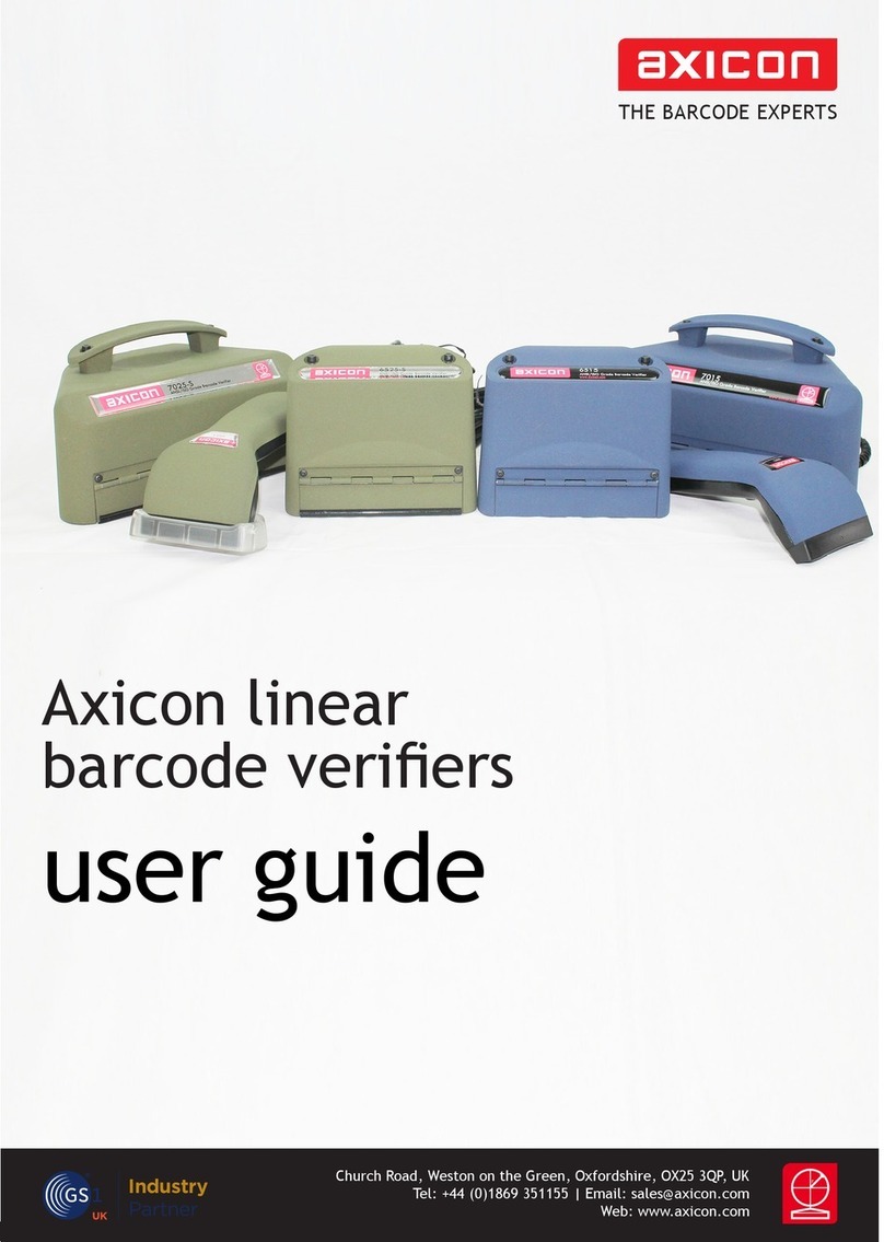
What’s in the transit case 7
Software Installation for Windows (all versions) 8
Hardware installation for Windows 9
Software and Hardware Installation for Apple Macintosh 13
User Calibration 14
Getting started with the Axicon verifier 16
Configuring the Axicon Verifier 19
AXICON SOFTWARE LICENCE AGREEMENT
Axicon Software Licence Terms – Licence Grant 24
Ownership of Software 24
Copies of Software 24
No Disassembly or Decryption of Software 24
Transfer of Software Licence 24
Termination of Software Licence 25
Export Requirements 25
Disclaimer 26
AXICON WARRANTY AND SERVICE CONTRACT
Warranty on all Products 27
Service Contract 28

- 2 -
VERIFIER SERVICING & FACTORY RECALIBRATION (VCAS)
Why CCD based verifiers require factory recalibration 29
Axicon Factory Recalibration Service (VCAS) 31
Other faults or damage 31
Equipment Rental Scheme 32
VCAS RECORD 33
CONTACT US 34

- 3 -
Conformance Certification
We Axicon Auto ID Ltd
of Church Road, Weston on the Green, Oxfordshire, OX25 3QP, UK
Declare under our sole responsibility that the product has been designed and
manufactured at our address in the year 2014 to perform verification of barcode
quality in accordance with the following standards:
ANSI X3. 182 ISO/IEC 15416 ISO/IEC 15420 ISO/IEC 16388
ISO/IEC 16390 ISO/IEC 15417 ISO/IEC 24724
We further declare that the verifier has been designed and manufactured to ensure
conformance to Primary Reference Test Symbols available from N.I.S.T. and
Traceable Reflectance Standards available from N.P.L. in accordance with ISO/IEC
15426-1.
Tolerances: Decodability: ±8%
Rmin: ±3%
Rmax: ±5%
Defect: ±8%
Modulation: ±12%
We also certify that this equipment conforms to the following standards:-
Barcoding: ISO/IEC 15426-1 VERIFIER CONFORMANCE STANDARD
European Safety EN 60950
Electromagnetic Compatibility EN 55022 & EN 55024
We also certify that the standards EN 60825 is not applicable to the product.
This equipment meets the requirements of the directives 89/336/EEC (Electromagnetic
Compatibility), 73/23/EEC (Low Voltage), based on our own relevant test reports.
Axicon Auto ID Ltd also certifies that this equipment, when used in conjunction with the
latest verifier software has all of the features required to meet the 21CFR Part 11 standard.
Church Road, Weston on the Green, Oxfordshire, OX25 3
Q
P, UK
Tel: +44
(
0
)
1869 351155 / Fax: +44
(
0
)
1869 351205 /


- 5 -
INTRODUCTION
Thank you for purchasing an Axicon Verifier. This short guide will enable
you to get started with your Axicon Verifier quickly and easily. A full
manual is available in electronic form on the software CD
The Axicon Verifier is designed to work with any PC running a version of
Microsoft Windows currently supported by Microsoft (some earlier
versions may also be supported – see notes) and with any Apple Macintosh
computer running Mac OS X version 10.4 or higher (up to but not including
Lion and Mountain Lion).
IMPORTANT INFORMATION
1. Your Axicon verifier is a piece of high precision quality control
equipment and should be handled with due care.
2. Please retain the plastic transit case. It will protect the equipment in
transit.
3. Only use power and data cables supplied by Axicon. Use of non-
approved accessories will invalidate the warranty.
4. If the verifier is dropped (or subjected to similar misuse) the accuracy
of the results may be affected. The unit should be returned to Axicon
immediately for servicing.
5. Axicon recommends that the verifier is factory recalibrated annually.
The unit should be returned to Axicon or to your approved Axicon
reseller for this check to be performed.
6. As the owner of an Axicon Verifier you are entitled to free software
updates for life. The latest copy of the software is always posted on
our website (www.axicon.com).
7. Subject to the terms of the license you are permitted to make
additional copies of the Axicon Verifier software.

- 6 -
8. For further, detailed information, including a trouble-shooting guide,
please read the manual which is available on the software CD.

- 7 -
WHAT’S IN THE TRANSIT CASE?
Please ensure that the following items are present upon receipt.
One of the following verifiers and the relevant cables:
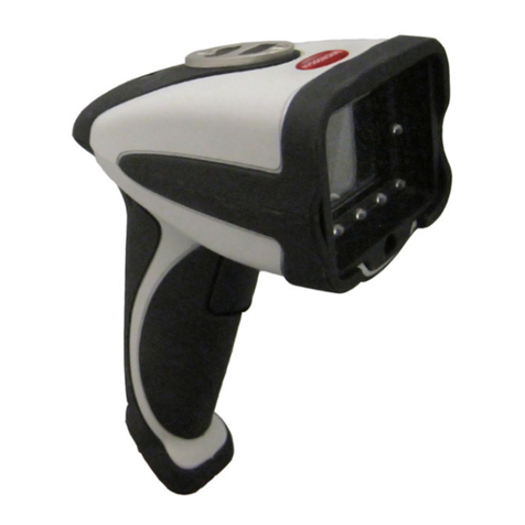
• Axicon 6000 Series – CCD verifier with USB cable attached.
• Axicon 6500 Series – CCD verifier with USB cable attached.
• Axicon 7000 Series – CCD verifier with USB cable attached.
• Software CD.
• Wallet containing Documentation Booklet (includes Start Up Guide)
and Calibration Sheet

- 8 -
SOFTWARE INSTALLATION
WINDOWS (ALL CURRENT VERSIONS)
1. Insert the CD into the CD drive
2. The Install Program should now start automatically. (If not, open the
CD using Windows Explorer and double-click the Autorun Program.)
3. Click “Install Axicon Verifier”
4. Follow the on-screen installation instructions for the next four
windows (Select a language, Welcome, Software License Agreement
and choose destination location) until you get to the “Select
Components to install” window.
5. At the “Select Components to Install” screen ensure that the boxes
relating to “Drivers” and “Main Program” are both ticked.
6. (If you have purchased certain additional optional features which are
password-protected you may be asked to enter the password(s) at
this stage through a separate dialogue box).
7. Click “Next” again to pass the “Select folder in start menu” window
8. If you have selected any password-protected features you will be
prompted to enter your serial number and passwords now. The
description appears in bold for the features you have chosen to
install and the passwords are at the front of this booklet.
If you have more than one verifier with password protected features
(see point 6 above) you should enter the serial number and
passwords for the first unit, then click “Enter Another” to enter the
serial number and passwords for the additional verifiers.
Click on “Next”
9. The software will now be installed.
10. Leave the software CD in the PC in order to install the USB drivers.
- 9 -
HARDWARE INSTALLATION FOR WINDOWS
LOADING USB DRIVERS
1. Plug the verifier into any available USB port directly on the
computer.
2. When prompted to install the drivers, make sure the CD is inserted
into the CD driver and follow the instructions.
After installation is completed you will find the “Axicon Verifier”
directory in “Start Menu/Programs” and a shortcut to the program on
your desktop.
• Double clicking the Axicon Verifier shortcut icon will now start the
software.
• Two windows will open: the Command window and the Summary
window.
• The LED array of your CCD should now be lit and the text in the
bottom right hand corner of the Command window should read “Ready
to scan”. If not, refer to the troubleshooting section of the manual on
the CD.

- 10 -
INSTALLATION FOR EARLIER VERSIONS OF WINDOWS AND
WHEN MANUAL INSTALLATION OF DRIVERS IS REQUIRED.
LOADING USB DRIVERS.
Note: When using much older (and Microsoft-Unsupported) versions of
Windows you may need to install the older version of the USB drivers.
These are available from Axicon on request.
Manual installation/Updating of the USB drivers (if required)
This section provides some guidance to users of the Axicon Verifiers who
need to update the USB drivers.
Firstly install the Axicon Verifier software (version 2.0.25.1 or later – note
that it is always possible to download the latest software from our
website).
As part of the software installation, the USB driver files will have been
copied to the folder that was chosen for the installation.
Connect the verifier and wait for the Hardware Wizard to start, or
initiate the Hardware Wizard from the Device Manager.
The following screen will appear for computers running Windows XP.
Select the option 'No' on this screen and then click the Next button.

- 11 -
Now choose the “Advanced” option to install from a list or specific
location and then click the “Next” button.
On this screen choose the 'Don't Search' option and again click on Next.
If any previous versions of the drivers have been installed, then you may
see them listed as shown above, however, at this point click on the Have
Disk button which will open the following dialogue.
If the default installation location was chosen when the Axicon Verifier
software was installed, then the appropriate driver files will have been
copied to the location shown in the dialogue above.
Browse to this location, or to the equivalent location if the default was
not chosen and then OK this dialogue.

- 12 -
The Hardware Wizard screen should now look like the one above and the
next step is to click the “Next” button to begin the driver installation.
A dialogue will pop up asking the user to confirm whether to continue the
installation or not.
Click on the 'Continue Anyway' button.
At this point, the driver files will be copied to the appropriate locations
and as soon as the installation finishes the verifier hardware will be heard
to beep as it powers up and becomes ready to use.
The Axicon Verifier software can now be launched and the software will
find and connect to the verifier hardware.

- 13 -
INSTALLATION FOR APPLE MACINTOSH
SOFTWARE
1. Insert the CD and double click on CD icon
2. Install USB Driver by double-clicking the USB Driver* icon. You will
need an administrator password. Installer will need to restart your
Mac after it has installed the driver.
3. To install the Verifier application, drag the icon to wherever you want
it.
4. To run the application double-click the Verifier icon.
* If you are using OS X 10.4 the text “You cannot install this software on
this disk (null)” may appear. If it does, click the “Go Back” button and
then the “Continue” button again and the driver should install.
HARDWARE
Plug the verifier into any available USB port.

- 14 -
USER CALIBRATION
Calibration with known reflectance values is essential to ensure the
accuracy of this equipment. It should be carried out after installation and
at regular intervals. (see below)
When the software detects an uncalibrated reader the following dialogue
box will appear “Reader XXX has not been calibrated”. You must click OK
to continue.
Please switch on your verifier at least five minutes before you start
to calibrate.
To calibrate you will need your calibration sheet, which you will find
in the wallet.
Take the calibration sheet out of the wallet and place it on a flat
surface.
For the Axicon 6000 Series use the EAN13 calibration code at the top
left of the sheet.
For the Axicon 6500 and 7000 Series use the large calibration code at
the bottom of the sheet.
Select the calibrate option.
For Windows versions: This is located in the “Options” menu
(or you can use the icon)
For Mac versions: This is located in the “Reader” menu

- 15 -
You will see a window with two edit boxes for minimum and
maximum reflectance values.
Ensure that the values shown in the window match the values printed
at the bottom of the calibration sheet.
(Modify the figures on the screen if necessary to ensure that they are
the same as the card
With the Calibration window open scan the calibration barcode 10
times. Then click the OK button.
The verifier is now calibrated and ready to use.
After calibration is completed, store the calibration sheet in its wallet,
away from light and physical damage. If your calibration sheet should
ever become damaged or discoloured in any way, please contact Axicon
or your supplier for a replacement.
NB: During the calibration process the software displays the
uncalibrated data and therefore reflectance values and grades
displayed behind the calibration window can be ignored.
Under normal operating conditions Axicon recommends calibrating the
verifier monthly (the verifier software is set up to remind you when it is
time to calibrate). In variable light and temperature conditions we
recommend more frequent calibration. The frequency can be changed if
required by using the “Options / Set-up /Calibration” path.

- 16 -
GETTING STARTED WITH YOUR AXICON VERIFIER
In countries where Axicon offer training courses we would strongly
recommend the use of these as the best way to get the most out of your
verifier and to understand all of it’s features.
For others, the following provides a general overview and start-point in
the verification process:- (This is not intended to be a comprehensive
instruction but will guide the user in the most frequently used features.)
When you first start the software you will see…
The “Command” Window :
This gives access to all of the main features of the verifier:-
Access can be by using pull down menus or by using icons
Icons are grouped according to function.
As you start using the verifier the main ones that you will use are the
display screens grouped at the centre of the top line of the command
window – From here to here:-
These cover the Command Screen (that we have seen already )…
A ”Summary Screen” that gives
the general quality of the
barcode

- 17 -
This Summary Screen shows the overall print quality of the barcode as
measured by the ISO/ANSI standards (the overall grade can be expressed
either as a number (ISO) – or as a letter (ANSI) – this can be altered as
required through the “Set-Up” icon (see below)
Information is also given on the bar-gain (ink spread), the overall
magnification of the barcode, validation of the check digit, structure,
and light margins (Quiet zones).
Ideally these will all show in green (pass) – any that have an amber or red
warning light beside them should be investigated.
NOTE: Be aware that just because a barcode receives a “pass” grade for
print quality does not necessarily mean that it is “fit for purpose” – after
all the wrong barcode number on a product may be printed perfectly but
that would not make it acceptable – Things like the size of the barcode
(magnification) and the location of the barcode are important if the
barcode is going to be “fit for purpose”.
The Details Screen…. Press
to get:-
This screen shows each of
the ISO/ANSI parameters
that are measured and
individually graded (as
both grades and
percentages).
Seven parameters are
graded and the lowest single grade becomes the overall grade for that
scan. (Ideally you should take a number of scans at different points in
the height of the same barcode – the verifier will automatically average
these for you to produce an overall print quality grade)

- 18 -
If the “Summary” Screen has shown poor print quality then the “Details”
screen is the ideal point to initially see what went wrong with the
barcode and hence focus the user on appropriate corrective action.
The Scan Profile Screen…. Press
to get:-
The Scan profile screen shows the user exactly what the barcode will look
like to a scanner.
At the top of the graph are the higher levels of reflectance from the
background and at the bottom of the graph are the lower levels of
reflectance from the darker bars.
Ideally the “sweep” (contrast) from top to bottom should be as great as
possible with smooth curves between the two, the “peaks” should ideally
be all around the same level and the “troughs” also at the same level.
If the cause of barcode problems is poor “modulation” or a high level of
defects then these can be shown overlaid on the graph by clicking the
appropriate box at the top of the Scan Profile Screen.
The Dimensional Measurements Screen…. Press
to get:-
If your “Details” screen has
shown a poor “Decodability”
grade then this is normally
because of bad dimensional
This manual suits for next models
2
Table of contents
Other Axicon Barcode Reader manuals

Axicon
Axicon 12000 User manual

Axicon
Axicon 6000 series User manual

Axicon
Axicon 6000-W User manual

Axicon
Axicon 6000 series User manual

Axicon
Axicon PV-1072 User manual

Axicon
Axicon 6025-S Operator's manual

Axicon
Axicon PV-1000 User manual

Axicon
Axicon 12000 Operator's manual

Axicon
Axicon PV-1072 User manual

Axicon
Axicon 12600 Operator's manual