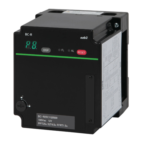
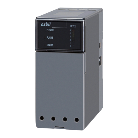
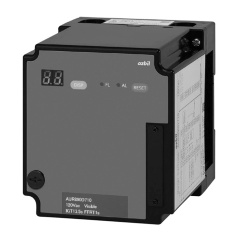
Azbil AUR450C User manual

Thank you for purchasing an Azbil
Corporation product.
This manual contains information for
ensuring the correct use of this product.
It also provides necessary information
for installation, maintenance, and
troubleshooting.
This manual should be read by those who
design and maintain equipment that uses
this product. Be sure to keep this manual
nearby for handy reference.
Dynamic Self-Checking
Burner Controller
Model AUR450C
User’s Manual
No. CP-SP-1264E

NOTICE
Be sure that the user receives this manual before the product is used.
Copying or duplicating this user’s manual in part or in whole is forbidden.
The information and specifications in this manual are subject to change
without notice.
Considerable effort has been made to ensure that this manual is free from
inaccuracies and omissions. If you should find an error or omission, please
contact the azbil Group.
In no event is Azbil Corporation liable to anyone for any indirect, special or
consequential damages as a result of using this product.
© 2007–2019 Azbil Corporation. All Rights Reserved.

i
Conventions Used in This Manual
The safety precautions explained in the following section aim to prevent injury to the operator and
others, and to prevent property damage.
WARNING Warnings are indicated when mishandling this product
might result in death or serious injury.
CAUTION
Cautions are indicated when mishandling this product might
result in minor injury to the user, or physical damage to the
product.
In describing the product, this manual uses the icons and notations listed below.
Use caution when handling the product.
The indicated action is prohibited.
Be sure to follow the indicated instructions.
Handling Precautions:
Handling Precautions indicate items that the user should pay attention to when handling
this device.
Note: Notes indicate information that might benefit the user.
(1), (2), (3): Numbers within parentheses indicate steps in a sequence or parts of an explanation.
This indicates the item or page that the user is requested to refer to.

ii
Safety Precautions
WARNING
This device does not have a prepurge function. Use this device as part of a system whose
design gives careful consideration to the prepurge timer and ignition sequence timing,
following established safety guidelines.
Connect loads (ignition transformer, solenoid valve, etc.) directly to the output terminals of
this device. Otherwise, combustion safety cannot be ensured.
When using an auxiliary relay due to lack of contact capacity, etc., take protective measures
in case a relay malfunction or contact welding occurs.
Never short-circuit the start contact in order to start and stop this device by switching the
power on and off. This is very important for reliable activation of the self-check circuit at
device startup. Failure to observe this warning could lead to an explosion.
Do not extend the lead wires of the reset input for more than the allowable length of 10
meters. Always input the reset command from beside the combustion equipment, not from a
remote location. Because a safety check cannot be made far from the equipment, there is an
increased risk of explosion.
Do not allow the pilot or main burner "Safety Time" (ignition trial time) to exceed the
specifications of the burner or equipment manufacturer. If they do, fuel may accumulate
in the combustion chamber and form an explosive air-fuel mixture, resulting in a serious
explosion hazard.
Before wiring, mounting, or removing this device, be sure to turn the power off. Wiring with
the power on can result in an electric shock.
Make sure that the AUD300C/500C does not detect ultraviolet rays other than those of the
burner. If the AUD300C/500C responds to other ultraviolet rays, flame failure in the burner
will not be detected. As a result, fuel will continue to be discharged, causing a serious
explosion hazard.
Do not connect a solenoid valve to the high voltage side of the circuit. If a ground fault
occurs, the ground fault current may energize and open the solenoid valve. This device will
not be able to prevent the valve from opening and fuel from flowing out.
Terminals and the connected flame detector signal cable retain an electrical charge even
after the power is turned OFF. To avoid electric shock, do not touch terminals F and G or the
cable immediately after power-off.
Carry out the pilot turndown test carefully. If the flame detector is set so that it detects a pilot
flame that is too small to ignite the main burner, this device will not be able to detect a flame
failure in the main burner.
In that case, fuel will continue to be supplied, causing a serious explosion hazard.
Before the pilot turndown test or ignition spark response test, make sure that all manual fuel
valves are closed.
If the pilot turndown test must be carried out repeatedly, completely shut down all
equipment each time the test is finished, and completely discharge unburned gas or fuel that
has accumulated in the ducts and combustion chamber. Failure to discharge unburned gas or
fuel may result in an explosion.

iii
WARNING
When the pilot turndown test is complete, turn OFF the power switch to shut down the power.
Restore all test jumpers and limit interlock/regulator settings to their previous states. If
operation begins without the above steps, damage to the equipment, gas leak or explosion
may result.
If lockout occurs, be sure to do a prepurge before restarting the system. If the combustion
chamber and gas flue are not ventilated to remove any unburned gas, the ignition process
may cause an explosion.
If a check is performed using a flame simulator without dismounting this device, be sure
to close the fuel valve. When a flame simulator is used during normal operation, the flame
detector reports that a flame is present even if the pilot burner and main burner are not
ignited, with the result that fuel is supplied continuously. This could cause an explosion.
This device has a limited product life. Beyond the product life, the risk of device failure
becomes higher. Replace this device within its product life.
If the system is locked out, do not reset it until the cause of the problem has been eliminated.
If lockout occurs, reset it only after removing the cause. Also, do not enter reset input
repeatedly.
Operating this product improperly could result in a serious combustion equipment accident.
Do not use the alarm output as safety output.
CAUTION
Be sure to use this device correctly, within the ranges specified in this user's manual.
Otherwise device failure or malfunction could result.
Do not install where exposed to any of the following:
• Certain chemicals or corrosive gases (ammonia, sulfur, chlorine, ethylene compounds, acid,
etc.).
• Splashing water or excessive humidity.
• High temperatures.
• Prolonged vibration.
This device has a protective structure equivalent to IP20. Take measures to protect it from
dust. In particular, if the equipment is designed to comply with CE/UL standards, be sure to
mount this device in an instrument panel with IP54 or equivalent protection.
Installation, wiring, inspection, adjustment, etc. should be carried out by a trained and
experienced technician who has knowledge and technical skills related to combustion
equipment and flame safeguard control devices.
Do not start regular operation of the equipment without first completing the trial-run
adjustments for this device, as well as the tests specified by the equipment manufacturer.

iv
CAUTION
Make sure the load connected to each terminal does not exceed the rating indicated in the
specifications.
If timers and auxiliary relays are needed for additional functions, select ones with high
reliability, and be sure to design the circuit correctly.
When installing and wiring, be sure to follow the instructions in this manual and in the user's
manual for the combustion equipment.
The ignition transformer ground lead should be connected directly to the burner body or to a
metallic part electrically connected to the burner body.
Run the high-voltage ignition transformer cable separately and keep it at least 10 cm away
from this device.
Keep power lines and ignition transformer high-voltage cables separate from the
AUD300C/500C cables and from the external reset input cable.
Make sure that ignition transformer high-voltage cables are properly connected to prevent
faulty contact. Faulty contact might generate high-frequency radio waves which can cause
malfunction.
Always connect the power supply last. Otherwise, touching a terminal accidentally could
result in electric shock or damage.
Always supply electric power at the voltage and frequency stated on the model label of this
device.
In keeping with technical standards for electrical equipment, the burner body must have an
earth ground connection with a resistance of less than 100 .
After the wiring is complete, be sure to check that it is correct. Incorrect wiring may cause
damage or faulty operation.
Make sure that the flame detector does not detect the ignition spark. If the flame detector
can detect the spark, change the detector's line of sight or change the ignition electrode's
position.
Only an experienced technician who has knowledge and technical skills related to
combustion equipment and combustion safety should carry out the pilot turndown test.
This product is equipped with functions that are extremely important for the safe operation
of combustion equipment. Carefully follow the instructions for its use that are given in this
user's manual.
If the safety shutoff has been activated, check all of the items on the checklists in chapter 4,
TRIAL-RUN ADJUSTMENT before restarting the equipment.
When doing a maintenance inspection of the burner, be sure to do the pilot turndown test.
Inspection must be done at least once a year.
Conduct periodic inspections in accordance with the user's manual of the equipment
manufacturer.

v
CAUTION
When cleaning the burner, clean the flame detector as well.
For transportation or storage of this device, remove it from the subbase and pack it in its
original box. It might be damaged if transported while mounted on a panel or the like.
Do not short the control load terminals (18-19, 18-20, 18-21, or 18-22) or the shutter
terminals (7-8). Internal fuses between these terminals will burn out if these terminals are
shorted.
If a fuse burns out, replace the entire product.

vi
The Role of This Manual
A total of 8 different manuals are available for the AUR450C. Read them as necessary for your specific requirements.
If a manual you require is not available, contact the azbil Group or its dealer.
Dynamic Self-Checking Burner Controller Model AUR450C User’s Manual
Manual No. CP-SP-1264E
This manual.
This manual should be read by personnel using the AUR450C for the first time, those in
charge of designing combustion equipment that uses the AUR450C or designing the hard-
ware for mounting the device in a control panel, and personnel performing maintenance.
The manual gives an overview of the product, its mounting and wiring for connection to
other equipment, its operation, trial-run adjustment, maintenance and inspection, and
specifications.
Dynamic Self-Checking Burner Controller Model AUR450C
User's Manual for Installation Manual No. CP-UM-5936JE
This manual is supplied with model AUR450C.Those who design or maintain equip-
ment that uses the AUR450C should read this manual thoroughly. This manual de-
scribes installation of this device.
Dynamic Self-Checking Burner Controller Model AUR450C User’s Manual for
Communication
Manual No. CP-SP-1176E
Those using the communications functions of the AUR450C should read this
manual.
It is necessary for making the program of the device that uses AUR450C. An opera-
tion status and various data of AUR450C can be read by using the communication.
This manual describes a details of display, outline of CPL communications, commu-
nications procedures, a list of communications data, how to remedy trouble, and
communications specifications.
User’s Manual for Smart Loader Package Model SLP-A45 for Dynamic Self-
Checking Burner Controller Model AUR450C
Manual No. CP-SP-1187E
This manual is supplied with the SLP-A00 Smart Loader Package.
The manual describes the software used to make various settings for smart loader
package using a personal computer. Personnel in charge of design or setup of a
system using the AUR450C must thoroughly read this manual.
The manual describes installation of the software into a personal computer, opera-
tion of the personal computer, various functions, and setup procedures.

vii
Advanced Ultraviolet Flame Detector Model AUD300C1000 User's Manual
Manual No. CP-SP-1141E
The manual describes the mounting, wiring, maintenance and inspection, and
troubleshooting when the AUD300C1000 when it is used in a safeguard control
system.
Explosion-Proof Advanced Ultraviolet Flame Detector Model AUD500C11000
User’s Manual
Manual No. CP-SP-1328E
It describes the mounting, wiring, maintenance, inspection, and troubleshooting
of the AUD500C when it is used with combustion equipment.
User’s Manual for Subbase Model Q241A104 for Dynamic Self-Checking
Burner Controller Model AUR450C
Manual No. CP-UM-5942JE
This manual is supplied with the subbase.Those who design or manufacture equip-
ment that uses the AUR450C should read this manual thoroughly. The subbase is
necessary when installing the AUR450C in a panel, etc. This manual describes in-
stallation and wiring of the subbase.
Analog Flame Meter Model FSP136A User's Manual
Manual No. CP-SP-1212E
It should be read in advance by those who use the FSP136A to check the voltage
of the AUR300C/350C/450C. This manual gives important information and precau-
tions for use of the meter.

viii
Organization of This User's Manual
This manual is organized as follows.
Chapter 1. OVERVIEW
An overview of the AUR450C.
Chapter 2. MOUNTING AND WIRING
Installation, wiring and wiring check methods.
Chapter 3. OPERATION
Internal block diagram of the AUR450C and sequence charts showing its operation.
Chapter 4. TRIAL-RUN ADJUSTMENT
Adjustment of the AUR450C and tests that are necessary before operating it.
Chapter 5. MAINTENANCE AND INSPECTION
Maintenance and inspection instructions, and troubleshooting flowchart.
Chapter 6. SPECIFICATIONS
General specifications, performance specifications, and external dimensions of the
AUR450C.

ix
Contents
Conventions Used in This Manual
Safety Precautions
The Role of This Manual
Organization of This User's Manual
Chapter 1. OVERVIEW 1-1
Overview 1-1
Features 1-1
System structure 1-2
Safety assurance functions 1-2
Precautions for designing equipment 1-3
Model selection table 1-3
Related devices 1-4
Certificates 1-4
Names and functions of parts 1-4
Description of 7-segment display 1-6
Terminal block signals 1-8
Chapter 2. MOUNTING AND WIRING 2-1
2-1 Mounting 2-1
Mounting locations 2-1
Mounting posture 2-2
Mounting the subbase 2-2
Mounting the controller 2-3
Dismounting the controller 2-3
2-2 Wiring 2-4
Wiring diagram 2-5
Connection to the Model AUD300C/500C 2-7
Checking the connection between the controller and the Model AUD300C/500C 2-7
Wiring to a solenoid valve 2-8
Wiring for continuous measurement of flame voltage 2-9
2-3 Communications Connections 2-11
Smart Loader connection 2-11
Connection of RS-485 communications 2-11
Connection to a 3-wire system 2-12
Connection to a 5-wire system 2-12
Chapter 3. OPERATION 3-1
Example of instrumentation for the Model AUR450C with an interrupted pilot 3-1
Precautions for instrumentation and circuit configuration with an interrupted pilot 3-1
Internal block diagram 3-2
Sequence charts 3-3

x
Example of instrumentation for the Model AUR450C with an intermittent pilot 3-10
Precautions for instrumentation and circuit configuration with an intermittent
pilot 3-10
Internal block diagram 3-11
Chapter 4. TRIAL-RUN ADJUSTMENT 4-1
Outline of adjustment 4-1
Preliminary inspection 4-2
Measurement of flame voltage (flame signal) 4-2
Pilot turndown test 4-3
Ignition spark response test 4-5
Safety shutoff test 4-6
Chapter 5. MAINTENANCE AND INSPECTION 5-1
Frequency of maintenance and inspection 5-1
Alarm code and description 5-2
Fault inspection flowchart 5-3
Chapter 6. SPECIFICATIONS 6-1
Specifications 6-1
External dimensions 6-3
China RoHS 6-3
Terms and Conditions

1-1
Chapter 1. OVERVIEW
Overview
The AUR450C Dynamic Self-Checking Burner Controller (hereafter the/this
device) is a flame safeguard controller that safely and automatically ignites and
monitors a gas or oil burner using the correct sequence of steps. It executes both
batch and continuous operations in combination with the AUD300C Advanced
Ultraviolet Flame Detector or the AUD500C Explosion-Proof Advanced Ultraviolet
Flame Detector.
This device monitors combustion while continuously checking the tube unit of
the AUD300C/500C and the flame detection circuits by driving the shutter of the
AUD300C/500C.
The device has a 7-segment display and communications function. Flame volt-
age, sequence status and alarm codes are displayed. For effective maintenance and
troubleshooting, a personal computer can be used to read data such as the system
status before the occurrence of various errors, past alarm history, operation time,
and number of combustion starts.
Features
1. Safety standards
* Self-declaration of conformity to standards is not permitted for combustion
safety equipment.
This product is certified to meet standards as noted below.
• UL: File No. MH27717
• CE: Gas Appliance Directive 0063BS1427
• FM: File No. 0003059531
2. Ignition sequence
Either 4-second or 8-second “Safety Time” (ignition trial time) is selectable by
model number. Either an intermittent or an interrupted pilot can be used, se-
lectable by output terminal.
3. Instrumentation and handling
This model requires less mounting space than a conventional model because of
its compact design. Since wiring can be done at the subbase, mounting or dis-
mounting the controller can be done with ease.
Flame monitoring output and alarm output contacts can be used as independent
non-voltage contacts. There is an input terminal for remote reset, or reset can be
done from the operating panel.
4. Display function
The LED indicators, which are especially useful for maintenance and trouble-
shooting, can be used to check the progress of the ignition sequence, the status
of flame detection, alarms, and the occurrence of events.
The LED indicators change color (green/orange/red) depending on the flame
voltage level. The 7-segment display is used to check sequence codes, alarm
codes, and event codes.

1-2
Chapter 1. OVERVIEW
System structure
This device is used to control the flame of combustion equipment, and is used in a
system like the one shown below.
Air pressure lower limit
interlock
Gas pressure lower limit
interlock
Gas pressure upper limit
interlock
Ignition
transformer
Air
Gas
MV1 MV2
PV1 PV2
T/C T/C
L
LH
UV
Controller
Overtemperature limit Vibration
detection limit
Combustion
chamber
Combustion
equipment
Exhaust damper
interlock
Flue
duct
Burner controller
BC
(AUR450C)
Limit/Interlock
PS
PS
IG
PS
TIC
TIA
Flame
detector
Exhaust
gas
Vibration
detector
Safety assurance functions
This device performs functions that are vital for burner operation and flame
monitoring.
• Combustion monitoring and safety shutdown
• Detects burner flame failure and shuts down the fuel supply immediately.
• In case of ignition failure or flame failure, shut down each value ignition trans-
former in a predetermined sequence.
• Startup, operation and shutdown of combustion equipment
• Operates each value ignition transformer in a predetermined order, with preset
timing.
• Fixed ignition timing
To ensure safety, the ignition circuit is so designed that ignition cannot continue
in excess of the specified time, even if part of the ignition circuit fails.
• Safe startup
• Checks flame detector and flame circuit for internal failure before every startup.
• If failure is detected, prevents burner startup.
• Checks for false flame detection or false discharge of the tube unit, failure of
the ignition circuit, and failure of the alarm circuit.
• Flame safeguard control in compliance with safety standards
This controller’s design is based on North American and European safety stan-
dards, and it is certified to meet them. This device can be used with combustion
safety equipment in Europe and North America.
• Dynamic self-checking
Checks continuously for sensor failure of the AUD300C/500C and for failure of
the flame detection circuit, even during the RUN stage of operation. If failure is
detected, fuel supply shutdown and lockout are immediately carried out.
• Protection against part failure
Failure Mode Effect Analysis (FMEA) has been done for all parts. Even if a part
failure occurs, safety will be maintained, and dangerous conditions such as the
following will not occur:
• Out-of-order ignition sequence.
• Dangerous sequence timing (longer ignition time)

1-3
Chapter 1. OVERVIEW
Precautions for designing equipment
When designing facilities that include combustion safety equipment, take the safety
directives listed below into careful consideration.
• Safety Engineering Directives for Industrial Heating Furnace Combustion
Equipment (Health, Labor and Welfare Ministry)
• General Safety Code for Industrial Combustion Furnaces (= JIS B 8415)
• Safety Engineering Directives for Industrial Gas Combustion Equipment (The
Japan Gas Association)
• Safety Guideline for Gas Boiler Combustion Equipment (The Japan Gas
Association)
• In the U.S.: Combustion Safety Guidelines (National Fire Protection
Association, NFPA86)
• Europe: EN 746 (Industrial Thermoprocessing Equipment)
93/68/EEC (CE Marking Directive) amending Appliances Burning Gaseous
Fuels.
Be sure to refer to the laws and standards of the relevant country when designing
equipment.
zImportant safety points
• Directly connect the load to this device.
• Structure the interlock so that power to the load can be directly turned off.
• Use the start check circuit during startup (do not short out the start contact input).
• Do not make a manual operation circuit or other bypass circuit for any load.
• Use a redundant shutdown system for both main valve and pilot valve.
zPrecautions for system design
Use external equipment to make a purge function, taking into consideration the
purge conditions and time settings.
Model selection table
The following shows the model selection table for this device:
Basic
model No.
Safety
time
Standards
compliance
Flame failure
response time
Power
supply
Additional
processing 1
Additional
processing 2
Description
AUR450C Dynamic self-checking burner controller
4 4±1 s
8 8±2 s
2 With standards compliance
2 1.5 s Nominal (2 s maximum)
3 3 s Nominal (4 s maximum)
1 100 V AC CE, UL, FM standards
2 200 V AC CE, FM standards
3 120 V AC CE, UL, FM standards
5 230 V AC CE, FM standards
0 -
00 Standard (no add. processing)
D0 Inspection certificate
T0 Tropicalization
DT Inspection certificate and tropicalization

1-4
Chapter 1. OVERVIEW
Related devices
The table below shows the devices that can be used with this device.
Item Name Model No. or parts No. Remarks
Compatible base Subbase Q241A104 -20 to +60 °C AWG14 to 18
Compatible flame detector Advanced Ultraviolet Flame
Detector
AUD300C -20 to +120 °C IV wire 2.0 mm2
AUD500C
(explosion-proof)
-20 to +60 °C 0.75 mm2cable
with silicone rubber insulation
Optional parts Flame simulator FSP300BC100 -
Analog flame meter FSP136A100 -
Surge absorber 83968019-001 -
Communications connector 81446848-001 1 piece
Loader Smart loader package SLP-A00J50 -
Certificates
• UL: File No. MH27717
• CE: Gas Appliance Directive (2009/142/EC) 0063BS1427
Low Voltage Directive (2014/35/EU)
Electromagnetic compatibility Directive (2014/30/EU)
RoHS Directive (2011/65/EU)
• FM: File No. 0003059531
Certificates are valid only for a combination of AUR450C, AUD300C, and
Q241A104.
Names and functions of parts
zController
7-segment display
Displays sequence codes,
alarm codes, event codes
and ame voltage.
LED indicators
Indicates current status of the
system.
Controller subbase screw
After the controller is placed on the subbase,
it is secured with this screw.
DISP switch
Switches between sequence code and ame voltage display.
RST switch
Resets the alarm (lockout).
ADDRESS switch
Sets the device's communications address.
RS-485 communications connector
Communications connector.
Loader jack
Connects to a personal computer
using a dedicated cable, when using
the PC Smart Loader program.
For the use of the loader, refer to;
User’s manual for Smart Loader Package Model SLP-A45
for Dynamic Self-Checking Burner Controller Model AUR450C
CP-SP-1187E.
Flame voltage terminals
Used for monitoring the ame voltage
(M3.5 screws).
Note: When the EVENT LED is lit, the event code can be
displayed.
All active events can be cleared at the same
time by pressing the DISP button for 2 s or
longer.
POWER
EVENT
SHUTTER
FLAME
ALARM
START
IG
PV
MV RST
DISP
FLAME
VOLTAGE
ADDRESS
LOADER
RS-485
DYNAMIC SELF CHECK
BURNER CONTROLLER
AUR450
Note
• There are covers on the RS-485 communications connector, loader jack, and
flame voltage terminals. For purposes of explanation, covers are not shown in the
above drawing.

1-5
Chapter 1. OVERVIEW
zLED display details
Name Color Description
POWER Green Lights up when the power is turned on
EVENT Orange Lights up when an event occurs
SHUTTER Green Lights up when the shutter is closed
FLAME Green * Lights up when a flame is detected
ALARM Red Lights up when there is an alarm
START Green Lights up when the start contact circuit is closed, and goes off
when an alarm is detected
IG Green Lights up when the ignition transformer output is on
PV Green Lights up when the interrupted pilot valve opening output is on
MV Green Lights up when the main valve opening output is on
* On the device, the color changes to green, orange or red as determined during setup.
The factory settings are green for a flame voltage of 2.5 V or more, orange for 1.6 to 2.4
V, and red for 1.5 V or less. The LED goes off if no flame is detected (K6 is off).
zSubbase (Q241A104) sold separately
13
14
15
16
17
18
19
20
21
22
23
24
1
2
3
4
5
6
7
8
9
10
11
12
2
2
2
2
Q241A104
Side cover
: Upper and bottom side covers can be
removed when putting in the wiring.
Remove when knockouts are not used.
Mounting hole
: Mounting holes are used when the subbase is
mounted on a panel.
Although there are 5 holes, use the 4 at the
corners to mount the device. Use M4 screws.
Terminal block
: M3.5 screws for connection of external wiring.
Hole for the body-subbase screw
: This threaded hole mates with the body-subbase
screw, which is used to attach the main body to
the subbase.
Knockouts
: Remove knockout discs to run in the wiring.
There are 2 knockout holes on the upper, bottom,
right and left sides and back, 10 holes in total.
The sides, upper, and bottom covers have 2
dierent diameter holes, to respond to any
wiring situation. Remove knockouts as needed.
Note
• The shape and dimensions of the terminal block are shown below. Wiring will be
easy if crimp type terminal lugs suitable for the dimensions written below.
4
6.3

1-6
Chapter 1. OVERVIEW
Description of 7-segment display
zSequence code display
Normally, a code is displayed corresponding to the present stage of the operation
sequence. The table below shows the displayed code and the concurrent stage in the
sequence.
Display Sequence Description
– – Standby Standby when the start contact input is off.
P1 Start check Start check of this device and of the AUD300C.
P2 Ignition trial Ignition of the pilot burner.
P3 Pilot Stabilization Check to confirm reliable pilot burner ignition.
P4 Main Trial Ignition of main burner.
P5 RUN Flame monitoring after main burner ignition.
PL Lockout Lockout
zAlarm code display
When lockout occurs, the display automatically changes to alarm code display, and
the lockout sequence code and alarm code are alternately displayed.
Display Alarm name Description
E0 Start check alarm The start check was not completed for some reason such
as momentary power failure or part malfunction.
E1 Interlock alarm Interlock occurred.
E2 False flame A false flame such as a remaining flame was detected.
E3 UV alarm A flame was detected even though the shutter output
was off.
E4 Ignition failure No flame was detected at the completion of the ignition
trial.
E5 Flame failure A flame failure occurred in the following sequence:
• Pilot Stabilization
• Main Trial
• RUN
EE Other When the cause of lockout cannot be identified:
• In cases where power was turned off before CPU error
determination
• In cases where vibration during transportation, etc.,
cause latch relay to switch to lockout
Handling Precautions
• If the DISP switch is pressed while an alarm code is displayed, the flame volt-
age is displayed rather than the alarm code. When DISP is pressed again, the
sequence code and the alarm code are alternately displayed.
• If the system is locked out and then reset, the display prior to lockout resumes.
For example, if lockout occurs while flame voltage is displayed, the display
changes to alarm display, in which the alarm code and sequence code are al-
ternately displayed. After reset, flame voltage display resumes.

1-7
Chapter 1. OVERVIEW
zFlame voltage display
Flame voltage is displayed as 2 digits.
If the 7-segment display shows 3.2, it means 3.2 V.
zEvent display
When a pre-selected, preset event occurs, the orange EVENT LED lights up. If the
DISP switch is pressed while EVENT is lit up, an event code from the table below is
displayed. However, the event code is not displayed if lockout has occurred.
All active events can be cleared at the same time by pressing the DISP button for 2 s
or longer.
Display Event name Description
A1 Ignition delay ON when the ignition delay time exceeds
the preset value.
A2 Shutter cycle count upper value
(1 minute)
ON when the shutter cycle count exceeds
the upper preset value.
A3 Shutter cycle count lower value
(1 minute)
ON when the shutter cycle count drops
below the lower preset value.
A4 Operation time for event ON when the time since startup exceeds
the preset value.
A5 Combustion time for event ON when the RUN time exceeds the preset
value.
A6 Combustion count for event ON when the combustion count exceeds
the preset value.
A7 Flame voltage upper value ON when the flame voltage exceeds the
preset value during RUN (display code: P5).
A8 Flame voltage lower value ON when the flame voltage drops below
the preset value during RUN (display code:
P5).
Handling Precautions
• When the product is shipped, no event settings are configured. Therefore,
it is necessary to configure event settings in order to have the EVENT LED
light up and to have an event code displayed when an event occurs.
For details how to event setup, refer to;
User’s manual for Smart Loader Package Model SLP-A45 for Dynamic
Self-Checking Burner Controller Model AUR450C (CP-SP-1187E).

1-8
Chapter 1. OVERVIEW
Terminal block signals
zSubbase terminal block
The table below describes the terminals on the subbase.
Terminal No. Description Rated
1 Model AUD300C/500C terminal F (blue)
2 Model AUD300C/500C terminal G (yellow)
3 Unused
4 Unused
5 Unused
6 Unused
7 Model AUD300C/500C shutter (white) 24 V DC 150 mA
8 Model AUD300C/500C shutter (white)
9 External reset input
10
11 Alarm output contact 75 VA max.
12
13 Power supply (H) 100/120/200/230 V AC
50/60 Hz
(depending on model No.)
14 Power supply (G)
15 Start contact input Contact resistance 100 Ω
max.
16 Start contact input
17 Interlock 100/120/200/230 V AC
50/60 Hz
Contact resistance 100 Ω
max.
18 Interlock
19 Ignition transformer 300 VA max. (cos φ = 0.5)
20 Main valve 200 VA max. (cos φ = 0.5)
21 Intermittent pilot 200 VA max. (cos φ = 0.5)
22 Interrupted pilot 200 VA max. (cos φ = 0.5)
23 Flame monitor output 75 VA max. (cos φ = 0.5)
24 Flame monitor output
zFlame voltage terminals
The table below describes the flame voltage terminals on the front panel.
Terminal No. Description Rated
+ Flame voltage output (+) 0 to 5 V DC *
- Flame voltage output (-)
* The flame voltage may reach approx. 7 V during self-discharge.
Table of contents
Other Azbil Controllers manuals

Azbil
Azbil SDC26 Instruction Manual

Azbil
Azbil C15 User manual

Azbil
Azbil F4Q User manual

Azbil
Azbil BH-101G0W0000 User manual

Azbil
Azbil INFILEX GC WY5311 User manual

Azbil
Azbil MY6050A1001 User manual

Azbil
Azbil AUR890 Series User manual

Azbil
Azbil MPC0002 User manual

Azbil
Azbil F4Q User manual

Azbil
Azbil Infilex ZM WY5322 User manual
Popular Controllers manuals by other brands

Full Gauge Controls
Full Gauge Controls MT-530 Super manual

McQuay
McQuay MicroTech III Installation and maintenance manual

Delem
Delem DA-52s Reference manual

Hanna Instruments
Hanna Instruments BL 983320-0 user manual

Disaster Area Designs
Disaster Area Designs DMC.micro user manual

YASKAWA
YASKAWA PROFINET 1000 Series Technical manual