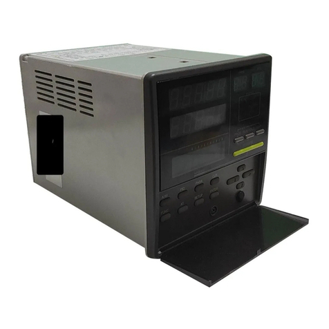
Azbil Azbil MIZCON Plus User manual

AB-6650
1
Specifications/Instructions
MIZCON™Plus
Cooling Tower Controller
Model R7010W
General
MIZCON™Plus (also written as ‘MIZCON+’) Model
R7010W is a conductivity and temperature controller for
cooling water.
MIZCON Plus keeps the conductivity of the cooling water
at the optimum level and thus precisely controls makeup
water. This enables the following:
- Saves makeup water and chemical.
- Ensures operating efficiency of chiller and
compressor.
- Prevents high-pressure cut-out of chiller and critical
damage of condenser.
- Prevents cooling tower and pipes from being clogged
with scale and other substances.
MIZCON Plus maintains the temperature of the cooling
water at the optimum level by controlling the operations of
cooling tower fan and electric heater. This allows the
chiller to operate at maximum efficiency and prevents the
cooling water from being frozen.
Model R7010W (controller) with
Part No. 81301430-001 (4-electrode sensor)
Note:
For the 4-electrode sensor, be sure to separately order by its
part number (Part No. 81301430-001 for 4 m long cable or
Part No. 81301430-002 for 20 m long cable).
Features
•Contamination resistant 4-electrode sensor:
4-electrode sensing element is resistant to
contamination serving long operation life with high
measuring accuracy.
•Conductivity temperature compensation:
Conductivity measuring accuracy is assured even with
temperature change, preventing over-concentration
and over-blowdown (overfeed) of the cooling water.
•Easy installation of the immersion sensor:
The sensor is immersion-type and thus facilitates the
installation.
•Conductivity alarm:
Cooling water conductivity out of the preset value (high
limit alarm setpoint) is reported with alarm.
•Conductivity / temperature PV (process value) output:
Measured conductivity and temperature are output via
4-20 mA DC analog output. Water quality is thus
constantly monitored for precise quality control.
•Temperature control:
Cooling water temperature can be controlled with DO
(2 points max.).
•Interlock operation:
Input for interlock with the cooling water pump is
equipped.
•Wide conductivity range:
Measuring range can be switched between 0-200 and
0-400 mS/m.
•Easy installation of the controller main unit:
Quick-fit screwless (clamp) terminals are provided
except power supply line. This facilitates the wiring
work. Besides, DIN rail mounting or screw mounting is
selectable for the controller (main unit) installation.

2 AB-6650
Safety Instructions
Please read instructions carefully and use the product as specified in this manual. Be sure to keep this manual near by
for ready reference.
Usage Restrictions
This product is targeted for general air conditioning. Do not use this product in a situation where human life may be
affected. If this product is used in a clean room or a place where reliability or control accuracy is particularly required,
please contact Azbil Corporation’s sales representative. Azbil Corporation will not bear any responsibility for the results
produced by the operators.
WARNING
•DANGER: To prevent the risk of severe or fatal electrical shock, always disconnect power source from the
controller power supply terminals before performing any wiring.
•Before replacing the controller (main unit), disconnect the power supply of the valve and other equipment
connected to the controller. Electrical shock may result.
•Before replacing the 4-electrode sensor, be sure to turn off the controller. Electrical shock may result.
•Do not disassemble the product. Electrical shock and equipment damage may result.
•Make sure all the wires are tightly connected. Fire and smoke due to heat generation of the equipment,
electrical shock, and equipment damage may result.
•Be sure to ground. Improper grounding may cause electrical shock and equipment damage.
•Do not detach the terminal cover except when connecting or disconnecting the wires. Be sure to reattach the
terminal cover after connecting or disconnecting the wires. Before detaching and attaching the terminal
cover, make sure all the wires and terminals are disconnected from the power source.
CAUTION (1/2)
•Installation must be performed by qualified personnel in accordance with all applicable safety standards.
•Installation must be carried out according to the operating conditions specified in this manual to prevent
equipment damages.
•All wiring must comply with local codes of indoor wiring and electric installation rules.
•Use crimp terminals with insulation for electric wires.
•Wire stripping length to be connected to the quick-fit screwless (clamp) terminal block must be 10 mm. If the
wire is stripped longer than 10 mm, the conductor will be exposed causing electrical shock and short-circuit
between adjacent terminals. If shorter, the conductor may not contact the terminal.
•If more than the rated power supply voltage is applied to the controller, controller replacement is required for
safety.
•Do not peel off the label with symbol.
•Lightning protection is required based on regional characteristics and building structure in order to minimize
lightning damage.
•After completing the wiring, be sure to peel off the protective sheet.
•Install the controller under the cooling tower, on a wall under an eave, and other locations unexposed to direct
sunlight and rain.
•For the controller installation, avoid weathered locations, and install the controller inside the rain-proof case if
necessary.
•When temperature control output is set to N.C. for anti-freeze electric heater, temperature control does not
interlock with the electric heater operation. Provide an additional circuit to prevent the heater from heating
when no water is left.
•Install the 4-electrode sensor inside the water tank or in a location (close to the tank) where water flows well.
•For the 4-elecrode sensor installation, do not allow the 4-elctrode sensor to directly contact the inner wall or
bottom of the water tank. Leave approx. 10 cm away from the inner wall and from the bottom.

3 AB-6650
CAUTION (2/2)
•Position the cable connected between the controller and the 4-elecrode sensor away from heavy-current
wiring and circuit to avoid induction current.
•Controller power needs to be supplied from the single-phase power source for noise reduction. If the
controller receives noise from the power supply line, provide isolating transformer and line filter.
•Do not position the cable connected between the controller and the 4-elecrode sensor or the wires for PV
output close to the inverter.
•Do not incinerate the controller or the 4-electrode sensor for waste disposal (the housings produce toxic gas
when incinerated). Do not recycle all or part of them, either.
•Dispose of the controller and the 4-electrode sensor in accordance with local regulations.
Trademark information:
MIZCON is a registered trademark of Azbil Corporation in Japan.
Model Numbers
Controller (main unit)
Base model
number
Fixed Temperature
PV*1output
Fixed Temperature
control output
Description
R7010W MIZCON Plus
- Control output of blowdown valve for cooling water:
potential free N.O./N.C.*2contact
- Conductivity PV output: 4-20 mA DC
- Alarm output: potential free N.O. contact
(for sensor error or conductivity over the high limit)
- Interlock input: potential free contact
1 ⎯
0 No temperature PV output
4 Cooling water temperature PV output: 4-20 mA DC
0 ⎯
0 No temperature control output
1 Temperature control output: potential free N.O. or N.C. contact ×1 pt.
2 Temperature control output: potential free N.O. or N.C. contact ×2 pts.
Notes:
∗1 PV: Process Value
∗2 N.O: Normally Open / N.C: Normally Closed
4-electrode sensor
Separate order is required for the sensor. Be sure to select your applicable sensor and order by its part number.
Part number Description
81301430-001 Immersion type 4-electrode sensor:
For Model R7010W (MIZCON Plus) / R7010B (MIZCON), with temperature sensing, with 4 m long cable
81301430-002 Immersion type 4-electrode sensor:
For Model R7010W (MIZCON Plus) / R7010B (MIZCON), with temperature sensing, with 20 m long cable

4 AB-6650
Specifications
Controller (main unit) (1/2)
Item Specification
Rated voltage 100 V AC to 240 V AC at 50 Hz/60Hz
Operating voltage 85 V AC to 264 V AC
Power supply
Power consumption 10 VA or less
Ambient temperature -20 °C to 50 °C
Ambient humidity 10 %RH to 90 % RH (Non-condensing)
Rated
operating
conditions Vibration Max. 5.9 m/s2(0.6 G) at 10 Hz to 150 Hz
Ambient temperature -20 °C to 60 °C
Ambient humidity 5 %RH to 95 % RH (Non-condensing)
Vibration for transport Max. 5.9 m/s2(0.6 G) at 10 Hz to 150 Hz
Environmental
conditions
Transport /
storage
conditions
Vibration for storage Max. 9.8 m/s2(1 G) at 10 Hz to 150 Hz
Power supply (‘power’) Green LED ON: Power ON, OFF: Power OFF
Operation standby (‘standby’) Green LED ON:
Operation in standby state (DI contact is open.)
Blow-down operation
(‘blowdown’)
Green LED ON: Cooling water being blown down
Temperature control outputs 1
and 2
(‘do1(temp)’ and ‘do2(temp)’)*1
Green LED ‘do1(temp)’ or ‘do2(temp)’ ON:
Temperature control DO contact is closed.
Alarm (‘alarm’) Red LED ON: Alarm output (DO) contact is closed.
PV and SP (‘pv’ and ‘sp’) Orange LED ‘pv’ or ‘sp’ ON: Process value or setpoint is indicated.
Control data
(window for 7-segment LEDs)
Red 7-segment LEDs: control data is indicated (to set or to display).
LED
operations
Indication
Units (‘mS/m’ and ‘°C’) Orange LED ‘mS/m’ or ‘°C’ ON: mS/m or °C is indicated.
Weight Approx. 500 g
Material / color Polycarbonate resin / light gray
Power supply terminals M3.5 screw terminal connectionTerminal connection
Terminals except power supply Quick-fit screwless (clamp) terminal connection
Conductivity measuring range Changeable between:
0 mS/m to 200 mS/m and 0 mS/m to 400 mS/m ranges
Interlock input
(When DI contact is open)
Potential free contact input
Rating: Max. 10 V DC, 5 mA
Temperature control set to N.O. :
Temperature control is stopped by opening DO contact.
Temperature control set to N.C.:
Temperature control is continued.
Cooling water blow-down valve output: Valve is fully closed.
Control output Rating: 100 V AC / 240 V AC, 3 A (cos φ= 0.4)
- Cooling water blow-down valve:
Potential free N.O./N.C. contact (SPDT)
- Alarm output contact: Potential free N.O. contact (SPST)
- Temperature control output contacts 1 and 2 (optional)
Potential free N.O. contacts (SPST)
Conductivity 4 mA DC to 20 mA DC (0 mS/m to 200 mS/m or 0 mS/m to 400
mS/m), 300 Ωor lower load resistance
Measuring (PV) output
(AO signals are isolated from
power supply.) Temperature 4 mA DC to 20 mA DC (0 °C to 50 °C), 300 Ωor lower load resistance
Conductivity 10 mS/m to 200 mS/m (200 mS/m range) or
20 mS/m to 400 mS/m (400 mS/m range)
Measuring range to display
Temperature 0 °C to 50 °C
Conductivity For 20 mS/m to 200 mS/m or 40 mS/m to 400 mS/m and 25 °C,
Control accuracy: ±4 %FS
Measuring output: ±5 %FS
Ambient temperature effect: ±0.2 %/°C Tc*2
Accuracy
Temperature Control accuracy: ±0.5 °C
Measuring output: ±1.0 °C
Ambient temperature effect: 0.02 °C/°C Tc*2
Notes:
∗1 LEDs for temperature control ouputs 1 and 2 are equipped depending on the models.
(do1(temp) LED is equipped with Model R7010W1X01, do1(temp) and do2(temp) LEDs are equipped with Model R7010W1X02.)
∗2 Tc: Temperature of the controller
5 AB-6650
(2/2)
Item Specification
Blow-down valve control operation Differential (DIF)
Valve open
Valve closed
Setpoint (SP)
Lower Higher
Conductivity high limit alarm
(Alarm is turned on by the
conductivity over OHSP for 3
consecutive minutes.)
High limit of differential (HDIF)
Alarm ON
Alarm OFF
High limit alarm setpoint (OHSP)
Lower Higher
Conductivity error detection
(for sensor damage/
malfunction detection)
Range SP
200 mS/m 10 mS/m
400 mS/m 20 mS/m
Alarm ON
Alarm OFF
Setpoint (SP)
Lower Higher
Alarm output operation
Either of these alarms is
output to the external device
Temperature error detection
(for sensor damage/
malfunction detection)
Alarm ON
Alarm OFF
-15 °C 65 °C
Lower Higher
Setting to N.O.
•Closes when temperature
error is input.
•Opens when interlock input
(DI) contact opens.
Differential (DIF)
Contact closed
Contact open
Setpoint (SP)
Lower Higher
Temperature control DO
contacts operation
(Temperature control DOs are
optional depending on the
model numbers.)
Setting to N.C.
•Opens when temperature
error is input.
•Continues open and close
operation when interlock
input (DI) contact opens.
Differential (DIF)
Contact closed
Contact open
Setpoint (SP)
Lower Higher
∗Setting N.C. is for anti-freeze electric heater. Operating status therefore is
maintained even when the cooling water pump is shut down. To prevent the
heater from heating when no water is left, provide an additional circuit.
4 mounting screws (M4)Accessories
1 label for the maintenance history of the 4-electrode sensor
Rain-proof case Part No. DY3001A2002
Extension cable for
4-electrode sensor
Part No. 81301475-001 (10 m long) / 81301475-002 (20 m long) /
81301475-003 (30 m long)
DIN rail mounting bracket Part No. 83104567-001
Replacement plates Part No. 83167610-001
2 plates, for mounting inside the former version of the rainproof case
(sold until March 31, 2005)
Varistor assembly Part No. 83167751-001
(To connect the varistor to MIZCON Plus, connect the ring terminals of
the varistor to the terminals 1 to 3 of the MIZCON Plus.)
Provide the varistor if the MIZCON Plus is installed in a location where
thunder often occurs.
Converter Model RYY792A3077 (Conversion between 4-20 mA current output
and 0-100 mV voltage output)
The converter is used to replace MIZCON Model RY7010B1008 with
the MIZCON Plus.
4-electrode sensor Part No. 81301430-001 (4 m long cable) / 81301430-002 (20 m long)
Parts and auxiliary device
requiring separate order
Resistor for field inspection Part No. 83167745-001
Conductivity
Conductivity
Temperature
Conductivity
Temperature
Temperature

6 AB-6650
4-electrode sensor
Item Specification
Ambient temperature Cooling water: 0 °C to 50 °C (Non-freezing)
Atmospheric air: -10 °C to 50 °C
Ambient humidity 0 %RH to 100 % RH
Rated
operating
conditions
Vibration Max. 9.8 m/s2(1 G) at 10 Hz to 150 Hz
Ambient temperature -20 °C to 60 °C
Ambient humidity 5 %RH to 95 % RH (Non-condensing)
Vibration for transport Max. 9.8 m/s2(1 G) at 10 Hz to 150 Hz
Environmental
conditions
Transport /
storage
conditions
Vibration for storage Max. 9.8 m/s2(1 G) at 10 Hz to 150 Hz
Internal resistance temperature detector (RTD) JIS* JPt100
Weight Part No. 81301430-001 (4 m long cable): 700 g
Part No. 81301430-002 (20 m long cable): 3000 g
Materials Stainless steel, polycarbonate resin
∗Note: JIS: Japanese Industrial Standards
Wire Specifications
Item Wire specifications Max. wiring
length
Condition
Power supply JIS* IV or JIS CVV 2.0 mm2or greater ⎯⎯
Ground JIS IV or JIS CVV 2.0 mm2or greater ⎯100 Ωor lower ground resistance
I/O (inputs/outputs) JIS IV, JIS CVV, or KPEV* (for low power circuit)
0.5 mm2, , 0.75 mm2, 0.9 mm2, or 1.25 mm2
100 m ⎯
4-electrode sensor Accessory cable and extension cable (0.5 mm2×6
cores)
34 m ⎯
∗Note: KPEV is a wiring standard provided by Furukawa Electric Co., Ltd.

7 AB-6650
Dimensions and Parts Identifications
Controller (main unit): Model R7010W
60 180
5 170 5
Power switch
Display and setting operation keys Terminal block (for except power supply terminals)
Terminals for power supply
Figure 1. Dimensions and parts identification: Controller (mm)
Process value/setpoint indication LED
Control value indication window (to set and display)
Unit (mS/m or °C) indication LED
Operation standby indication LED
Blow-down operation indication LED
Temperature control output 1 indication LED*
Temperature control output 2 indication LED*
Alarm indication LED
Power supply indication LED
Note:
Temperature control outputs 1 and 2 LEDs are
optional depending on the model numbers.
Figure 2. LEDs of the controller
17.5 85 17.5
120

8 AB-6650
63
3940 or 19940 (cable length)
170
85 85
330 20
370
350 10
42
4-electrode sensor: Part No. 81301430-001 (4 m long cable) / 81301430-002 (20 m long cable)
80
Wire hanging tab for the sensor installation
Sensor cable (φ12.5 )
Sampling probe (with
the electrodes inside)
29 70
Figure 3. Dimensions and parts identification: 4-electrode sensor (mm)
Rain-proof case: Part No. DY3001A2002
280
40 200 40 151
Controllermountinghole
(6holes)
63 74 63 122
Mounting hole
(φ7 ×4 holes,
for wall-mount) Mounting hole
(φ14 ×4 holes, for U-bolt to mount onto a DN50 pipe)
Mounting hole (M4, for ground line)
Wire conduit hole (φ22 ×4 holes)
65 50 50 50 65
Figure 4. Dimensions and parts identification:
Rain-proof case with the front door closed (mm)
Figure 5. Dimensions and parts identification:
Rain-proof case with the front door open (mm)

9 AB-6650
Installation
1. Controller
Precautions for installation
•Install the controller main unit inside the rain-proof case (Part No. DY3001A2002) or mount onto DIN rail. To install the
controller inside the former version of the rain-proof case (sold on March 31, 2005 or before), replacement plates (Part
No. 83167610-001, 2 plates/set) are required. Since the former version is designed for MIZCON, not for MIZCON Plus,
the intervals between the mounting holes of the controller (MIZCON Plus) and of the case are different.
•Install in a location with the specified environmental conditions (-20 to 50 °C, 10 to 90 %RH).
•The cable of the 4-electrode sensor can be extended up to 34 m. Install therefore the controller within the radius of
34 m the cooling water tank (where the sensor is installed).
Installation procedure:
MIZCON Plus controller inside the latest version of the rain-proof case (Part No. DY3001A2002)
Install the controller on the inside wall of the rain-proof case with four M4 screws (supplied with the MIZCON Plus
controller ). The controller can be mounted either on the higher part of the wall or on the lower part of the wall. (See Figs.
6 and 7.)
Mounting onto the higher part
4 mounting holes
Controller
4 M4 screws
Rain-proof case
Figure 6. Controller installation inside the latest version of the rain-proof case (higher part)
Mounting onto the lower part
4 mounting holes
Controller
4 M4 screws
Rain-proofcase
Figure 7. Controller installation inside the latest version of the rain-proof case (lower part)

10 AB-6650
Installation procedure:
MIZCON Plus controller replacing MIZCON inside the former version of the rain-proof case (Part No.
DY3001A2002)
To install the controller inside the former version of the rain-proof case sold on March 31, 2005 or before, to replace
MIZCON with MIZCON Plus in other words, replacement plates (Part No. 83167610-001, 2 plates/set) are required
because the intervals between the mounting holes of the controller and of the case are different. Be sure to separately
order the replacement plates.
Install the controller on the inside wall of the rain-proof case with four M4 screws (supplied with the MIZCON Plus
controller) and the 2 replacement parts. For the replacement parts installation, reuse two M4 screws supplied with the
MIZCON controller. The controller can be mounted either on the higher part of the wall or on the lower part of the wall.
(See Figs. 8 and 9.)
Mounting onto the higher part
4 mounting holes
Controller
4 M4 screws
Rain-proofcase
2 M4 screws (supplied with MIZCON)
and 2 replacement plates
Figure 8. Controller replacement inside the former version of the rain-proof case (higher part)
Mounting onto the lower part
4 mounting holes
2 M4 screws (supplied with MIZCON)
and 2 replacement plates
Controller
4 M4 screws
Rain-proof case
Figure 9. Controller replacement inside the former version of the rain-proof case (lower part)

11 AB-6650
Installation procedure: Controller onto DIN rail
To mount onto DIN rail, DIN rail mounting brackets (Part No. 83104567-001) are required. Be sure to separately order
the brackets.
Mount the controller onto the DIN rail so that it does not fall from the DIN rail. Fix the bilateral sides of the controller with
DIN rail mounting brackets.
Controller
DINrail
Controller
Hook
DIN rail
Figure 10. Controller installation onto DIN rail
Detaching procedure: Controller from DIN rail
To detach the controller from DIN rail, unhook the controller by pulling the DIN rail holder downward using a screwdriver
and lifting the lower part of the body as shown in Fig. 11. Do not strongly pull the DIN rail holder. If DIN rail holder comes
off from the controller, reinsert it until it clicks.
Controller
DIN rail
DINrailholder
Screwdriver
DIN rail holder
Screwdriver
Figure 11. Controller detaching from DIN rail

12 AB-6650
50* 72.5 47.5 50
100*
Clearance of the controller inside the rain-proof case / onto DIN rail
DIN rail
(unnecessary for the installation
inside the rain-proof case)
∗Note:
Hatched area shows 50 for rain-proof case
clearance required for 100 for DIN rail
the controller installation.
45 45
Figure 12. Clearance of the controller
2. 4-Electrode Sensor
Precautions for installation
•Install the 4-electrode sensor inside the sump of the
water tank or in a location (close to the tank) where
water flows well. Avoid installing the sensor close to
the water feeding point.
•Do not allow the 4-elctrode sensor to directly contact
the inner wall or the bottom of the water tank. Leave
approx. 10 cm away from the inner wall and from the
bottom for installation.
Installation procedure: 4-electrode sensor
Fix the 4-electrode sensor with φ2-4 mm wire inside the
sump of the water tank. Roll one end of the wire and
hang the 4-electrode sensor . (Lead the wire end
through the wire hanging tab of the sensor.) Tie the
other end of the wire to the cooling tower.
Cable of the 4-electrode sensor
Wire hanging tab of the 4-electrode sensor
4-elecrode sensor
Approx. 10 cm
Wire
(φ2-4 mm)
Circulating water
Approx. 10 cm
Figure 13. 4-electrode sensor installation in the water tank
3. Rain-Proof Case
Precautions for installation
•Install the rain-proof case (with the controller inside)
under the cooling tower, on a wall under an eave, and
other locations unexposed to direct sunlight and rain.
Installation procedure: Rain-proof case
Mount the rain-proof case on a wall with screws or on a
DN50 pipe with a u-bolt.
(See Fig. 4 for the mounting hole dimensions.)
Fan Multiple Units Control
MIZCON Plus is not applicable to the multiple units
control of fans. That is, MIZCON Plus alone cannot
control the cooling tower composed of multiple cells
since the cooling water temperature of each cell may
differ.
Note:
Keeping to run the cooling tower fan until the cooling water
temperature drops down to the low limit increases the
chiller COP (Coefficient of Performance). Multiple units
control of the fans therefore is not recommended even with
an additional controller based on the representative
temperature.
1 cell
Cooling tower
Figure 14. Cooling tower composed of multiple cells
Blow-down wate
r
Sump of the
cooling water tank

13 AB-6650
Wiring
WARNING
•Be sure to disconnect the power source from MIZCON Plus before wiring the 4-electrode sensor. Electrical
shock may result.
CAUTION
•Before activating the MIZCON Plus, make sure all the wires are correctly connected. Faulty wiring may cause
equipment damage.
Wiring procedure
Power supply line (for M3.5 screw terminal connection):
Crimp the M3.5 crimp terminals on the wire ends, and connect them to the power supply terminal block.
Lines except the power supply line (for clamp terminal connection):
For the lines except the power supply line, the quick-ft screwless terminal blocks are provided. Follow the procedure
below for the wire connection.
1) Strip 10 mm sheath of a wire end.
2) Make sure that there is no wire fiber protruded from the bare wire (stripped part).
3) Insert the wire end while pressing the clamp release button using a slotted screwdriver. (Button-pressing force: 23 N)
4) Pull out the screwdriver with the wire end inserted. Then, lightly pull the wire to make sure it is tightly connected.
Again, make sure that there is no wire fiber protruded from the bare wire connected.
Protective sheet:
After all the wires are completely connected, peel off the protective sheets until MIZCON Plus is activated.
Protective sheets
Figure 15. Protective sheets
Wire arrangement
1) Power supply (3 terminals)
Terminal number Terminal indication Description
1 Power supply input
2
Power supply input
3 Ground
Screw terminals
2) Signals 1 (10 terminals)
Terminal number Terminal indication Description
4 blow down NC Motorized ball valve N.C.
5 blow down COM Motorized ball valve common
6 blow down COM Motorized ball valve common
7 blow down NO Motorized ball valve N.O.
8 alarm DO
9 alarm DO
High limit alarm output
10 int.lock DI
11 int.lock DI
Interlock contact input
12 c.out + Conductivity 4-20 mA output (+)
13 c.out - Conductivity 4-20 mA output (-)
Quick-fit screwless
(clamp) terminals
∼

14 AB-6650
3 2 1
Motorized valve
Model VY6300
1 2 3
blow down
NC COM NO
4 5 6 7
BR WH RD
Motorized valve
Model VY6100
12 3
blow down
NC COM NO
4 5 6 7
S COM O
Motorized valve
Model VY6020
1 2 3
blow down
NC COM NO
4 5 6 7
3) 4-electrode sensor (6 terminals)
Terminal number Terminal indication Description
14 electrode BR (brown) Current electrode (+)
15 electrode RD (red) Voltage electrode (+)
16 electrode BK (black) Voltage electrode (-)
17 electrode YL (yellow) Current electrode (-) /
Temperature (B2)
18 electrode GN (green) Temperature (B1)
19 electrode WH (white) Temperature (A)
Quick-fit screwless
(clamp) terminals
4) Signals 2 (6 terminals)
Terminal number Terminal indication Description
20 t.out + Temperature 4-20 mA output (+)
21 t.out - Temperature 4-20 mA output (-)
22 do(temp) DO1
23 do(temp) DO1
Temperature contact output 1
24 do(temp) DO2
25 do(temp) DO2
Temperature contact output 2
Quick-fit screwless
(clamp) terminals
Wiring to motorized ball valve
MIZCON Plus controller MIZCON Plus controller
100-240 V AC 100-240 V AC
100-240 V AC 100-240 V AC 100-240 V AC 100-240 V AC
power power power power
Figure 16. Wiring to Model VY6300 Figure 17. Wiring to Model VY6100
MIZCON Plus controller
100-240 V AC
100-240 V AC 100-240 V AC
power power
Figure 18. Wiring to Model VY6020

15 AB-6650
Operation
CAUTION
•Set the temperature setpoints that satisfy your chiller manufacturer.
Default values and setting ranges of the setpoints
1) Default values and setting ranges of the setpoints (for 200mS/m conductivity range)
Item Description Indication Default value Setting range
Range rEng (RENG) 200 mS/m 200 mS/m range or 400 mS/m range
Setpoint SP 80 mS/m
5-200 mS/m
∗Set the value greater than DIF.
SP <DIF is automatically changed to SP = DIF.
SP >OHSP is automatically changed to
SP = OHSP.
Differential dIF (DIF) 5 mS/m 5-15 mS/m
∗Set the value smaller than SP.
DIF >SP is automatically changed to DIF = SP.
DIF < HDIF is automatically changed to
DIF = HDIF.
High limit alarm oHSP
(OHSP)
100 mS/m 5-200 mS/m
∗Set the value greater than SP.
OHSP <SP is invalid.
Conductivity
High limit alarm
differential
HdIF (HDIF) 5 mS/m 5-15 mS/m
∗Set the value smaller than DIF.
HDIF >DIF is invalid.
Temperature output 1
Setpoint
SP1 25 °C 0-48.3 °C
∗Set the value smaller than [50 - DIF1].
SP1 >[50 - DIF1] is automatically changed to
SP1 = [50 - DIF1].
Temperature output 1
Differential
dIF1 (DIF1) 2.0 °C 1.7-5.6 °C
∗Set the value smaller than [50 - SP1].
DIF1 >[50 - SP1] is automatically changed to
DIF1 = [50 - SP1].
Temperature control
output 1
Temperature output 1
N.O. or N.C. contact
STT1 no (N.O.)
Switch the contact between N.O and N.C.
Temperature output 2
Setpoint
SP2 4 °C 0-48.3 °C
∗Set the value smaller than [50 - DIF2].
SP2 >[50 - DIF2] is automatically changed to
SP2 = [50 - DIF2].
Temperature output 2
Differential
DIF2 2.0 °C 1.7-5.6 °C
∗Set the value smaller than [50 - SP2].
DIF2 >[50 - SP2] is automatically changed to
DIF2 = [50 - SP2].
Temperature control
output 2
Temperature output 2
N.O. or N.C. contact
STT2 nc (N.C.)
Set the contact to no or nc.
∗Switch the contact between N.C. and N.O. N.C.
setting is for anti-freeze electric heater. Operating
status therefore is maintained even when the
cooling water pump is shut down. To prevent the
heater from heating when no water is left, provide
an additional circuit.
2) Setpoints and setting ranges for 400 mS/m conductivity range
Item Description Indication Default value Setting range
Setpoint SP 200 mS/m
10-400 mS/m
∗Set the value greater than DIF.
SP <DIF is automatically changed to SP = DIF.
SP >OHSP is automatically changed to
SP = OHSP.
Differential dIF (DIF) 10 mS/m 10-30 mS/m
∗Set the value smaller than SP.
DIF >SP is automatically changed to DIF = SP.
DIF <HDIF is automatically changed to
DIF = HDIF.
High limit alarm oHSP
(OHSP)
240 mS/m 10-400 mS/m
∗Set the value greater than SP.
OHSP <SP is invalid.
Conductivity
High limit alarm
differential
HdIF (HDIF) 10 mS/m 10-30 mS/m
∗Set the value smaller than DIF.
HDIF >DIF is invalid.

16 AB-6650
Setting Operations
7-segment LEDs indication
0
1
2
3
45 6 7
8
9
A
a
C
c
D
d
E
e
F
f
G
g
H
h
I
i
L
l
N
n
O
o
P
p
R
r
S
s
T
t
The settings on this page are available for all the models of MIZCON Plus series.
When power is
turned on…
Press
[mode]
key.
Press [mode] key.
Conductivity PV
Temperature PV
Indication changes by
pressing [unit] key
Continued to P.18.
Press [mode] key.
Conductivity PV range setting menu
The PV range currently set is
displayed.
PV range setting mode
All the digits flash.
Change the range (200 mS/m
or 400 mS/m) with [↑] and [↓]
keys.
The PV range newly set is displayed.
∗If setpoint (SP) smaller than differential
(DIF) is entered, SP equal to DIF is
automatically set regardless of the
entered SP.
If SP greater than OHSP (high limit
alarm SP) is entered, SP equal to
OHSP is automatically set regardless
of the entered SP.
Conductivity SP setting menu
The SP currently set is displayed.
SP setting mode
The first digit (left ‘0’ in this case)
flashes.
Select the digit to change with
[→] key, and change the value
with [↑] and [↓] keys.
The range newly set is displayed.
Press [mode] key.
Continued to the following page.
Changeover of PV range
: conductivity
(To change 200 to 400 mS/m)
Setting of blow-down SP
:conductivity
(To change 80 to 120 mS/m)
unit :
Changes over between conductivity.
enter :
Displays the conductivity range.
(The range 200.mS/m or 400 mS/m
currently set is displayed for 2
seconds
)
Press
[enter]
key.
Press
[enter]
key.
Press
[→]
key.
Press
[enter]
key.
Press [enter] key.
Press
[→]
key.
Press
[enter]
key.
Press
[enter]
key.
Press
[enter]
key.
Press [enter] key.

17 AB-6650
The settings on this page are available for all the models of MIZCON Plus series.
Continued from the previous page.
∗If differential (DIF) greater than
SP is entered, DIF equal to SP
is automatically set.
If DIF smaller than HDIF (high
limit alarm DIF) is entered, DIF
equal to HDIF is automatically
set regardless of DIF entered.
Conductivity DIF
setting menu
The DIF currently set
is displayed.
DIF setting mode
The first digit (‘0’ in this
case) flashes.
Select the digit to change
with [→] key, and change
the value with [↑] and [↓]
keys.
The DIF newly set is displayed.
Press
[mode]
key.
∗High limit alarm setpoint
(OHSP) smaller than SP is
invalid.
Conductivity OHSP
setting menu.
The SP currently set is
displayed.
SP setting mode
The first digit (’1’ in this
case) flashes.
Select the digit to change
with [→] key, and change
the value with [↑] and [↓]
keys.
The range newly set is displayed.
Press
[mode]
key.
∗High limit alarm differential
(HDIF) greater than DIF is
invalid.
Conductivity HDIF
setting menu
The HDIF currently set is
displayed.
HDIF setting mode
The first digit (‘0’ in this
case) flashes.
Select the digit to change
with [→] key, and change
the value with [↑] and [↓]
keys.
The range newly set is displayed.
Setting of blow-down DIF
: conductivity
(To change 5 to 15 mS/m)
Press
[enter]
key.
Press
[enter]
key.
Press
[→]
key.
Press
[enter]
key.
Press [enter] key.
Setting of OHSP
: conductivity
(To change 100 to 120 mS/m)
Press
[enter]
key.
Press
[enter]
key.
Press
[→]
key.
Press
[enter]
key.
Press [enter] key.
Setting of HDIF
: conductivity
(To change 5 to 10 mS/m)
Press
[enter]
key.
Press
[enter]
key.
Press
[→]
key.
Press
[enter]
key.
Press [enter] key.

18 AB-6650
The settings on this page are available for Models R7010WX01 and R7010WX02..
Continued from “Temperature PV” on P.16.
Temperature SP1
setting menu
The SP1 currently set
is displayed.
SP1 setting mode
The first digit (‘2’ in this
case) flashes.
Select the digit to change
with [→] key, and change
the value with [↑] and [↓]
keys.
The SP1 newly set is displayed.
Press
[mode]
key.
Temperature DIF1
setting menu.
The DIF1 currently set is
displayed.
DIF1 setting mode
The first digit (’2’ in this
case) flashes.
Select the digit to change
with [→] key, and change
the value with [↑] and [↓]
keys.
The DIF1 newly set is displayed.
Press
[mode]
key.
Conductivity STT1
setting menu
The STT1 currently set is
displayed.
STT1 setting mode
All the digits flash.
Change the output contact
type (N.O. or N.C.) with
[↑] and [↓] keys.
The STT1 newly set is displayed.
Press [mode] key.
Continued to the following page.
Setting of SP1 (output 1 SP)
: temperature
(To change 25 to 20 °C)
Setting of DIF1 (output 1 DIF)
: temperature
(To change 2 to 2.5 °C)
Changeover of STT1
(N.O. or N.C. for output 1)
: temperature
(To change N.O. to N.C.)
Press
[enter]
key.
Press
[enter]
key.
Press
[→]
key.
Press
[enter]
key.
Press [enter] key.
Press
[enter]
key.
Press
[enter]
key.
Press
[→]
key.
Press
[enter]
key.
Press [enter] key.
Press
[enter]
key.
Press
[enter]
key.
Press
[→]
key.
Press
[enter]
key.
Press [enter] key.

19 AB-6650
The settings on this page are available for Model R7010WX02..
Continued from the previous page.
Temperature SP2
setting menu
The SP2 currently set
is displayed.
SP2 setting mode
The first digit (‘4’ in this
case) flashes.
Select the digit to change
with [→] key, and change
the value with [↑] and [↓]
keys.
The SP2 newly set is displayed.
Press
[mode]
key.
Temperature DIF2
setting menu.
The DIF1 currently set is
displayed.
DIF1 setting mode
The first digit (’2’ in this
case) flashes.
Select the digit to change
with [→] key, and change
the value with [↑] and [↓]
keys.
The DIF2 newly set is displayed.
Press
[mode]
key.
Conductivity STT2
setting menu
The STT2 currently set is
displayed.
STT2 setting mode
All the digits flash.
Change the output contact
type (N.O. or N.C.) with
[↑] and [↓] keys.
The STT2 newly set is displayed.
Setting of SP2 (output 2 SP)
: temperature
(To change 4 to 3 °C)
Setting of DIF2 (output 2 DIF)
: temperature
(To change 2 to 2.5 °C)
Changeover of STT2
(N.O. or N.C. for output 2)
: temperature
(To change N.O. to N.C.)
Press
[enter]
key.
Press
[enter]
key.
Press
[→]
key.
Press
[enter]
key.
Press [enter] key.
Press
[enter]
key.
Press
[enter]
key.
Press
[→]
key.
Press
[enter]
key.
Press [enter] key.
Press
[enter]
key.
Press
[enter]
key.
Press
[→]
key.
Press
[enter]
key.
Press [enter] key.

20 AB-6650
Inspection and Maintenance
Controller
MIZCON Plus controller does not require to be periodically cleaned. Remove the dust covered the top and bottom vent
holes (slits) of the controller housing if necessary.
4-electrode sensor
Scale and slime coated the electrodes may prevent the electrodes to contact water. Periodically take the 4-electrode
sensor out of the cooling water tank to inspect and cleanse.
1. Inspecting and cleansing period
•For the MIZCON Plus used for a general cooling tower, inspect and cleanse the sensor once every 2 months.
•For other than the above, inspect and cleanse the sensor 1 month after the sensor activated. Then, schedule the next
inspection based on the results of the first inspection. (Once every 2 months in general.)
2. Inspection
Check the water sampling probe. If the inside of the probe including the electrodes are coated with slim, scale, and
other substances, cleanse the probe. See Fig. 19.
Sampling probe of the 4-electrode sensor
Electrode
Substances coating the inside of sampling probe
Figure 19. Inspection of the 4-electrode sensor (sampling probe)
CAUTION
•Be sure to turn off the power switch of the controller before replacing the 4-electrode sensor.
•MIZCON Plus requires 2 hours after the power is turned on to stably operate.
3. Cleansing
•Lightly brush the inside of the sampling probe using toothbrush with alkaline cleanser to remove the substances
coating there. Then rinse well with water. Do not use metal brush.
•Brush the 4 electrodes well to remove all the substances. The substances coating the electrodes may cause
measuring error.
Figure 20. Cleansing of the electrodes
4. MIZCON Plus in long-term shutdown
To deactivate MIZCPON Plus for a long term, take the 4-electrode sensor out of the cooling water tank, cleanse, rinse,
dry, and then put it in a plastic bag for storage. Cleans and rinse the sensor beforehand when using it again.
5. Replacement
Replace the 4-electrode sensor every 3 to 5 years.
Be sure to turn off the power switch of the controller before replacing the sensor.
Electrode
Before cleansed After cleansed
This manual suits for next models
1
Table of contents
Other Azbil Controllers manuals

Azbil
Azbil INFILEX GC WY5311 User manual

Azbil
Azbil Infilex GC WY5111 User manual

Azbil
Azbil C1M User manual

Azbil
Azbil Infilex FC User manual

Azbil
Azbil C25 User manual

Azbil
Azbil AUR890 Series User manual

Azbil
Azbil MPC0002 User manual

Azbil
Azbil KZ03 Series User manual

Azbil
Azbil C45 User manual

Azbil
Azbil BC-R25 Series User manual
Popular Controllers manuals by other brands

NEC
NEC uPD98502 user manual

Daktronics
Daktronics SPORTSOUND SSR-200 GEN II Operation manual

Klark Teknik
Klark Teknik HELIX DN9848E Operator's manual

DERUN LIGHTING TECHNOLOGY
DERUN LIGHTING TECHNOLOGY DR-CON-IR20M-3CH-LV user manual

Toshiba
Toshiba TOSVERT VF-AS1 Series instruction manual

IBM
IBM ServeRAID M5210 user guide