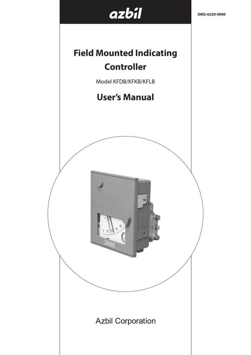
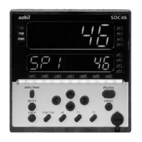
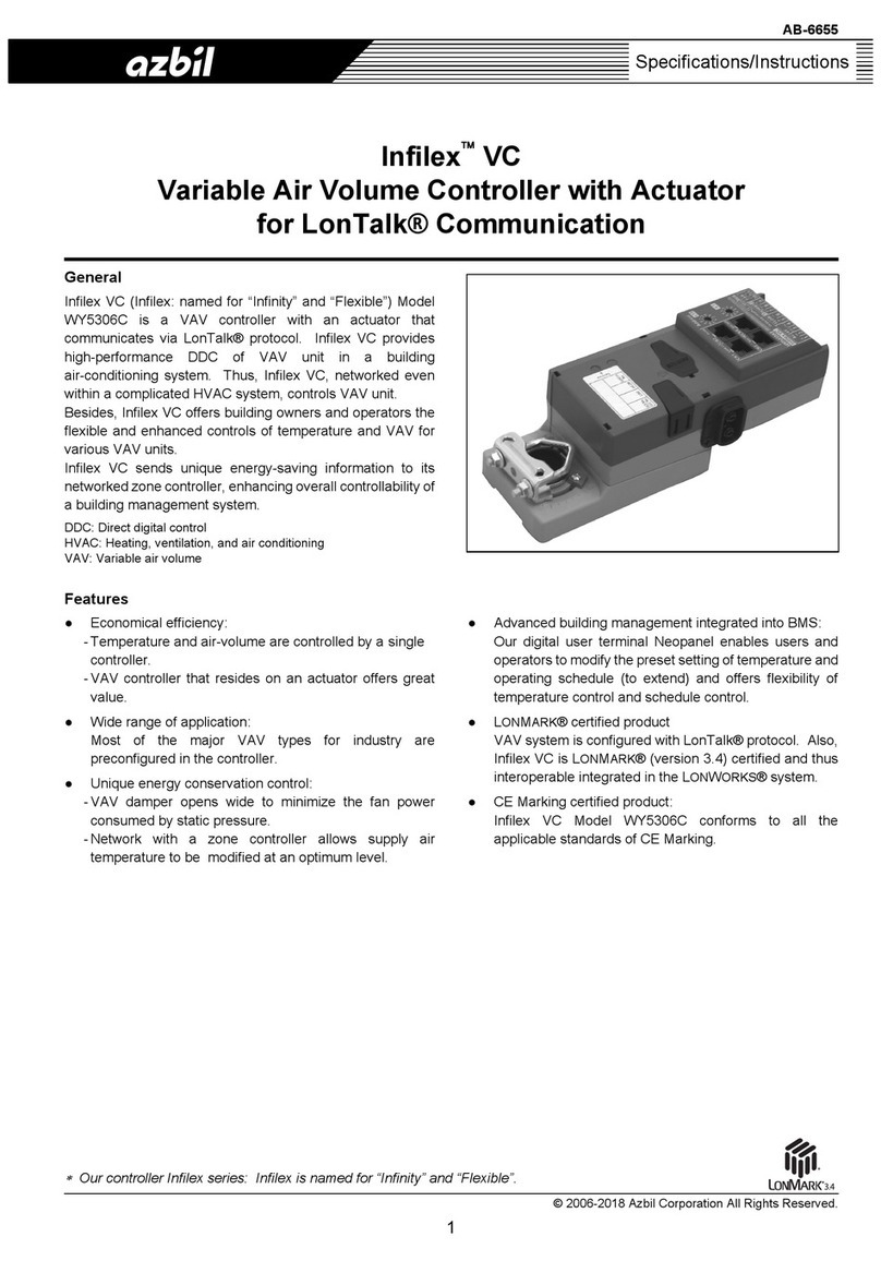
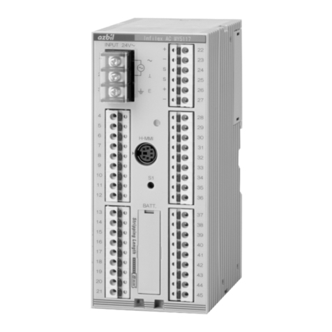
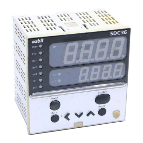
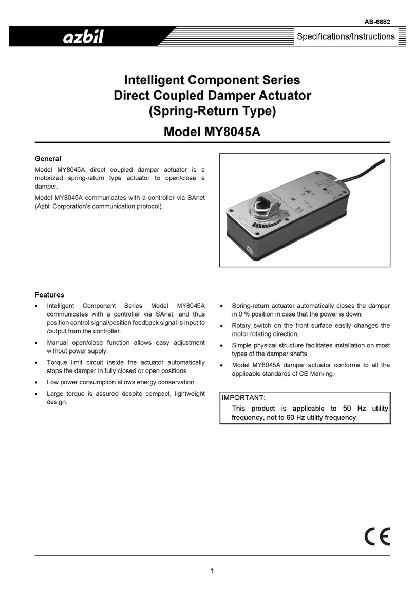
Azbil MPC0002 User manual

™
Thank you for purchasing your Azbil
Corporation product.
This manual contains information for
ensuring the safe and correct use of
the product.
Those designing or maintaining
equipment that uses this product
should first read and understand
this manual. This manual contains
information not only for installation,
but also for maintenance,
troubleshooting, etc. Be sure to keep it
nearby for handy reference.
Panel Mount
Mass Flow Controller
Model MPC9500/0002/0005/0020
User’s Manual
for Installation and configuration
No. CP-SP-1153E

NOTICE
Please make sure that this manual is available to the user of the product.
Unauthorized duplication of this user’s manual in part or in whole is
forbidden. The information and specifications in this manual are subject to
change without notice.
Considerable effort has been made to ensure that this manual is complete
and accurate, but if you should find an omission or error, please contact us.
In no event is Azbil Corporation liable to anyone for any indirect, special, or
consequential damages as a result of using this product.
© 2004–2019 Azbil Corporation. All Rights Reserved.
The µF™ is a trademark of Azbil Corporation in Japan.
Micro Flow Sensor™ and MPC™ are trademarks of Azbil Corporation.

i
Conventions Used in This Manual
The safety precautions explained below aim to prevent injury to you and others, and to prevent property damage.
WARNING Warnings are indicated when mishandling this product may
result in death or serious injury.
CAUTION Cautions are indicated when mishandling this product may
result in minor injury or property damage only.
In describing the product, this manual uses the icons and conventions listed below.
Indicates that caution is required in handling.
The indicated action is prohibited.
Be sure to follow the indicated instructions.
Handling Precautions:
Information to be aware of when handling.
Note: Indicates information that may be useful.
: Indicates an item or page to which the user may refer.
(1) (2) (3): Steps in a sequence or parts of a figure, etc.
>>
: Indicates the result of an operation, or the status after the operation.
0FF This indicates 7-segment indication on the setup display.
“OK” lamp This indicates an LED lamp on the setup display.
[ENT] key This indicates a key on the setup display.

ii
Safety Precautions
WARNING
Never allow gases that are within explosive limits to pass through this controller.
Doing so might result in explosion accidents.
Do not use this controller for gases other than standard compatible gas types (Air/Nitrogen,
argon and carbon dioxide (CO2)).
Do not use this device for medical instruments.
CAUTION
Prevent foreign matter from entering the controller.
If the rust, water droplet, oil mist or dust in the piping flows into the controller, measurement
error might occur and result in damaging the controller. If there is a possibility that are any
foreign matter flows into the controller, provide a filter or mist trap capable of eliminating
more than 0.1 µm foreign matter at the upstream, and periodically inspect and replace the
filter.
Use this controller within the operating differential pressure range. Also, do not apply
pressure outside the pressure resistance range.
Doing so might damage this controller.
The valve on this device cannot completely stop a flow.
If complete shutoff is required, provide a separate shutoff valve.
Also, if an external shutoff valve is closed, it is necessary also to fully close this device’s valve
using either of the following methods:
• Set the flow rate to zero.
• Set the operation mode to fully closed.
If this valve remains in control mode when the external shutoff valve is closed (zero flow
rate), there will be an excessively large momentary flow when the external shutoff valve is
opened.
Also, in control mode or with the valve forced fully open, if the external shutoff valve is
closed continuously, the MPC’s overheating prevention limit (AL71) will be activated and the
electrical current driving the valve will be forcibly limited.
When this controller is mounted on a panel, use piping which does not give stress to the
controller case during and after the piping work. If a metal piping is directly connected to the
pipe connection port of this controller, the case might be deformed or damaged.
The power supply circuit of this controller and the I/O circuit are not isolated each other.
Therefore, ensure that the power supply of this controller is isolated from the power supply
for external devices (insulate the power supply). If a common power supply is used for the
controller and the external devices, it might cause malfunction or faulty operation.
Do not allow lead clippings, chips or water to enter this controller case.
Failure to do so might cause malfunction or faulty operation.
For the model with analog I/O function, do not apply a negative-voltage or large voltage
more than 5 V to the analog setting input terminal.
Doing so might cause malfunction or faulty operation.
This device is a precision instrument. Do not drop it nor subject it to shock. Doing so might
damage the device.
iii
CAUTION
Be sure to check that the wiring is correct before you turn the power ON.
Incorrect wiring might cause damage or malfunction.
If there is a risk of a power surge caused by lightning, use a surge absorber (surge protector)
to prevent fire or device failure.

iv
A total of 3 different manuals are available for the Panel Mount Mass Flow Controller MPC. Read them as necessary
for your specific requirements. If a manual you require is not available, contact the azbil Group or its dealer.
Panel Mount Mass Flow Controller Model MPC9500/0002/0005/0020
User’s Manual for Installation and configuration
Document No. CP-SP-1153E
This manual.
This manual is optional (sold separately). Personnel in charge of design, manufacture,
operation, and/or maintenance of a system using this device must thoroughly read this
manual. This manual describes the installation, wiring, major functions and settings,
operating procedures, troubleshooting, and detailed specifications.
Panel-Mount Mass Flow Controller Model MPC 9500/0002/0005/0020
User’s Manual
Document No. CP-UM-5317E
This manual is supplied with the product.
Personnel in charge of design and/or manufacture of a system using this
device must thoroughly read this manual. This manual describes the safety
precautions, installation, wiring, and primary specifications. For further
information about operation, refer to other manuals, “Installation”.
Panel Mount Mass Flow Controller Model MPC9500/0002/0005/0020
User’s Manual for Communication Functions
Document No. CP-SP-1154E
Those using the communications functions of the MPC should read this manual.
This manual describes an outline of communications, wiring, communications
procedures, a list of MPC communications data, how to remedy trouble, and
communications specifications.
The Role of This Manual

v
Organization of This User’s Manual
This manual is organized as shown below.
Chapter 1. INTRODUCTION
This chapter briefly describes this device, its features and the model selection guide.
Chapter 2. NAMES AND FUNCTIONS OF PARTS
This chapter describes the Names and functions of parts on this device.
Chapter 3. MOUNTING AND WIRING
This chapter describes installation, mounting, wiring and initial settings on this
device.
Chapter 4. BASIC OPERATION
This chapter describes the basic operations for using this device.
Chapter 5. ADVANCED OPERATION
This chapter describes how to set the functions and parameters on this device.
Chapter 6. TROUBLESHOOTING
This chapter describes how to investigate and remedy trouble that may occur
during operation of this device.
Chapter 7. SPECIFICATIONS
This chapter describes the specifications and external dimensions of this device.

vi
Contents
Conventions Used in This Manual
Safety Precautions
The Role of This Manual
Organization of This User’s Manual
Chapter 1. INTRODUCTION 1-1
Introduction 1-1
Functions 1-1
Model selection guide 1-4
Chapter 2. NAMES AND FUNCTIONS OF PARTS 2-1
Display 2-1
Rear view 2-1
Chapter 3. MOUNTING AND WIRING 3-1
Mounting 3-2
Wiring 3-6
Chapter 4. BASIC OPERATION 4-1
4 - 1 Switching Displays 4-1
Instantaneous flowrate display (+ setting flowrate display) 4-1
4 - 2 Setting the Flowrate 4-3
Procedure for changing flowrate in digital setting 4-3
Procedure for changing flowrate in analog setting (a model with analog input /
output function) 4-5
4 - 3 Selecting the Operating Mode 4-6
Chapter 5. ADVANCED OPERATION 5-1
5 - 1 Function Setup 5-2
Function setup item list 5-3
5 - 2 Parameter Setup 5-6
Setup method 5-6
Chapter 6. TROUBLESHOOTING 6-1
Alarm code display 6-1
Other troubles 6-2
Chapter 7. SPECIFICATIONS 7-1
Specifications 7-1
Relationship between flowrate and differential pressure with valve fully
opened (in air) 7-6

1-1
Chapter 1. INTRODUCTION
Introduction
The MPC high performance digital mass flow controller has been developed for the
general industrial market featuring high speed and wide range flowrate control, the
following features are offered:
• The MPC integrates the advanced technologies of an ultra high speed response
flow velocity sensor, the µF (Micro Flow) sensor made using Azbil Corporation
proprietary technology, an ultra compact proportional solenoid valve, a new
flow channel structure and advanced actuator control technology achieves the
realization of the mass flow controller, which can be mounted on the panel of the
equipments.
• This is a compact (48 X 48 mm mask size) and light weight (approx. 300 g) mass
flow controller.
• Easy operation and easy mounting can be realized in good harmony when
replacing from a float type flow meter. In addition, the automatic control of mass
flow rate and remote flow setting change can be performed.
• There is almost no influence of temperature and pressure fluctuations by
integrating a µF sensor.
• A wide variety of functions are provided as a standard function to respond to the
various needs of the users.
• In case of a float type flow meter, the pressure and temperature compensation is
inevitable. In addition, if the design conditions (gas specific gravity, secondary
back pressure, etc.) are different from the conditions for use, the reading
value is required to convert by a specific calculation formula. However, these
inconvenient operation is no more required with the mass flow control.
Functions
• Multi-setup function
Up to four preset flowrate settings can be instantaneously switched to by key
operation or external switching input.
• Gas type switching function
The gas type to be used can be selected from the standard compatible gases by
key operation.
• Gas type setting function
The user can set any gas type conversion factors to accommodate the gases other
than standard compatible gases or mixed gases.
• Valve forced open/close function (selecting the operation mode)
The valve can be forcibly fully opened or fully closed by key operation or external
switching input.
• Slow start function
Sudden changes in the control flowrate, when control is started or when the
flowrate setting value is changed, can be suppressed.
The control speed can be changed in eight stages within the range from about 1
to 6 seconds.

1-2
Chapter 1. INTRODUCTION
• Flowrate integration function
The fowrate can be integrated up to eight digits (99,999,999 count).
(The display is switched in four digits at a time.)
MPC9500: 0.01 L in unit
MPC0002/0005: 0.1 L in unit
MPC0020: 1 L in unit
The count can be reset by key operation or external switching input.
Integration start/stop/reset can be remote-controlled by external switching input.
After a reset by key operation, the integration calculation is started automatically.
However, if a reset (contact ON) is carried out by external switching input,
integration is resumed by the contact turning OFF.
• Valve drive output display
The valve drive output value can be displayed in the unit of 0.0 to 100.0 %.
The increase or decrease of supply pressure and the choking of piping can be
detected.
• Alarm display/output/shut-off
The flowrate deviation alarm can be output by detecting the deviation between
setting flowrate and control flowrate. The alarm judgment delay time can also
be set. When a flowrate alarm occurs or an alarm occurs during controller self-
diagnostics, the event signal is output, the valve can be forcibly fully closed or
fully opened at your choise also.
• Event lamp light up/output
Two of the following event types can be output:
• Alarm output (When the flowrate deviation alarm or self-diagnostics occurs.)
• Flowrate upper/lower limit output (Output by comparison to the optional
upper/lower flowrate limit setting value.)
• Integration count up output (When the integration setting flowrate is
exceeded.)
• Integration pulse output (Pulse can be output for each integration display
unit.)
• OK output (When the control flowrate is within the "set point ± allowable
range".)
• The operating mode can be identified and output externally as an event.
The output ON delay time can also be set. However, the delay cannot be set
to integration pulse output. In addition, the output logic can be reversed (at
normal state: ON, at event occurrence: OFF). However, the output is always
OFF during power OFF.
• "OK" lamp light up / output
The "OK" lamp can be made to light when the control flowrate is within the
“setting value ± allowable range”. This function is very handy for verifying at a
glance whether or not the new setting value is being followed properly when a
setting value is changed. The "OK" lamp output can also be used as an interlock
signal for subsequent processes by assigning it to event output and loading it to a
sequence program.

1-3
Chapter 1. INTRODUCTION
• Automatic shut-off function
The valve can be shut off automatically under the following conditions:
• When the integration count value reaches the setting value.
• When one of the alarms, including flowrate alarms, occurs.
However, the valve of this device does not have a capability of complete shut-
off. When the complete shut-off is required, provide a separate shut-off valve
externally.
• Automatic reset of integration count at start of control function
Start of control and integration count reset can be carried out simultaneously
by a single action (key operation or external switching input). Combining this
function with the automatic shut-off function described above is handy for
shutting the valve off when a fixed number of integration values have been
counted repeatedly.
• Direct setup function
This function allows users to easily change the flowrate setup.
This function is useful when you frequently change setting values, for example,
when you adjust the preset flowrate during trial operation.
• Loader communication function
Connecting a loader cable (sold separately) to the loader jack at the rear side of
this device enables direct communication with a personal computer in the form
of one to one using the communication program made by user. By using this
loader communication, various settings in the function setup and the flowrate
setup can be configured from a personal computer, and the control flowrate or
alarm status can be read out with the personal computer.

1-4
Chapter 1. INTRODUCTION
Model selection guide
Basic
model
No.
Control
flow
range
Dis-
play
Mate-
rial
Connec-
tion
Gas
type
No
use
Option
1
Option
2
Option
3
Option
4
Code Description
MPC Panel mount mass flow controller
9500 0.020 to 0.500 L/min(standard) *1
0002 0.08 to 2.00 L/min(standard) *1
0005 0.10 to 5.00 L/min(standard) *1
0020 0.4 to 20.0 L/min(standard) *1
B Model with integrated display
B Brass
R Rc1/8
N Air/Nitrogen *2
0 -
0 None
1
With analog input/output function
(without RS-485 communication
function)
2
With RS-485 communication
function
(without analog input/output
function)
0 Without optional function
D Inspection certificate
Y Traceability certification
0 Product version
*1 L/min(standard) indicates the volume flowrate per minute (L/min) converted to 20 °C, and 101.325 kPa (1 atm).
The reference temperature can also be changed to 0 °C, 25 °C and 35 °C.
*2 The Air/Nitrogen is set as a factory setting.
The MPC can be used for argon and carbon dioxide (CO2) by setup change.

2-1
Chapter 2. NAMES AND FUNCTIONS OF PARTS
Display
LOK SP1 SP2 SP3 EV1 EV2
DISP
PV
SP
ENT
Upper display: Displays the instantaneous flowrate value
(7-segment display).
When the display is switched, it also displays the
integrated flowrate value (upper 4 digits),
parameter setup item, function setup item or alarm details.
Lower display: Displays the set flowrate
(7-segment display).
When the display is switched, it also
displays the operation mode,
integrated flowrate values (lower 4 digits),
value drive output, parameter setup values,
function setup values.
Operation lamp
L: Indicates that the integrated flowrate is
displayed.
Flashes when an integration event occurs.
OK: Lights when the control flowrate is within
the "setting value ± alowable range".
Flashes when the operating mode is valve
fully-open.
SP1 to SP3: The lamp corresponding to the SP No.
which is used at multi-setup is lit.
EV1, EV2: Lights when the event output is ON.
[ENT] key: Used when setting the SP value and storing
the value. It also can be used for the
integrated flowrate resetting and alarm
resetting.
[DISP] key: Used when switching
the details of display.
[<], [V], [ ]keys:
Used when incrementing/decrementing
the digit or moving to a desired digit.
Note
• The definition of the terms used in this manual is as follows:
SP (Set Point): Set flowrate value
PV (Process Variable): Instantaneous flowrate value (control flowrate)
Operation mode: 3 mode of "valve fully-closed / valve control / valve fully-
open"
Rear view
Pipe connection outlet port:
This is the out flow side port.
Pipe connection inlet port:
This is the in flow side port.
Connector:
1 2 3 4 5 6 7 8 9
Loader jack:
Connects to a personal computer by
using a dedicated loader cable sold separately.


3-1
Chapter 3. MOUNTING AND WIRING
WARNING
Never allow gases that are within explosive limits to pass through this controller.
Doing so might result in explosion accidents.
Do not use this controller for gases other than standard compatible gas types (Air/Nitrogen,
argon and carbon dioxide (CO
2)).
CAUTION
Prevent foreign matter from entering the controller.
If the rust, water droplet, oil mist or dust in the piping flows into the controller, measurement
error might occur and result in damaging the controller. If there is a possibility that are any
foreign matter flows into the controller, provide a filter or mist trap capable of eliminating
more than 0.1 µm foreign matter at the upstream, and periodically inspect and replace the
filter.
Use this controller within the operating differential pressure range. Also, do not apply
pressure outside the pressure resistance range.
Doing so might damage this controller.
The valve on this device cannot completely stop a flow.
If complete shutoff is required, provide a separate shutoff valve.
Also, if an external shutoff valve is closed, it is necessary also to fully close this device's valve
using either of the following methods:
• Set the flow rate to zero.
• Set the operation mode to fully closed.
If this valve remains in control mode when the external shutoff valve is closed (zero flow rate),
there will be an excessively large momentary flow when the external shutoff valve is opened.
Also, in control mode or with the valve forced fully open, if the external shutoff valve is closed
continuously, the MPC's overheating prevention limit (
AL71) will be activated and the electrical
current driving the valve will be forcibly limited.
When this controller is mounted on a panel, use piping which does not give stress to the
controller case during and after the piping work. If a metal piping is directly connected to the
pipe connection port of this controller, the case might be deformed or damaged.
Do not allow lead clippings, chips or water to enter this controller case.
Failure to do so might cause malfunction or faulty operation.
The part between the power supply circuit of this controller and the I/O circuit is not isolated.
Therefore, ensure that the power supply of this controller is isolated from the power supply
for external devices (insulate the power supply). If a common power supply is used for the
controller and the external devices, it might cause malfunction or faulty operation.
For the model with analog I/O function, do not apply a negative-voltage or large voltage more
than 5 V to the analog setting input terminal.
Doing so might cause malfunction or faulty operation.
This device is a precision instrument. Do not drop it nor subject it to shock. Doing so might
damage the device.
3-2
Chapter 3. MOUNTING AND WIRING
CAUTION
Be sure to check that the wiring is correct before you turn the power ON.
Incorrect wiring might cause damage or malfunction.
If there is a risk of a power surge caused by lightning, use a surge absorber (surge protector)
to prevent fire or device failure.
Mounting
Avoid mounting this controller in the following locations:
• Locations subject to high and low temperature and humidity
• Locations subject to sudden changes in temperature and condensation
• Locations subject to be filled with corrosive gases and flammable gases
• Locations whose atmospheres contain large amounts of dirt and dust, salt,
conductive substances such as iron powder, water droplets, oil mist and organic
solvents
• Locations directly subject to mechanical vibration or shock
• Locations subject to direct sunlight and rain
• Locations subject to splashing of oil or chemicals
• Locations close to sources of electrical noise
• Locations where strong magnetic or electrical fields are generated

3-3
Chapter 3. MOUNTING AND WIRING
z Joint connection
• Connect the joint by holding the hexagonal section of the pipe connection port of
the body with a spanner (or wrench).
Handling Precautions
• Do not hold the case of the controller with your hand when screwing the
joint into the connection port. Doing so might deform the body.
Incorrect
• Screw the joint with an appropriate torque as recommended by the
joint manufacturer. Exceeding the torque limits will cause damage the
connection port.
• Apply appropriate amount of sealant. Do not coat the top most thread of the
screw. Remove any dirt or burrs from inside the joint.
Good example Bad example
Sealant
Sealant

3-4
Chapter 3. MOUNTING AND WIRING
z External dimensions
unit : mm
48
LOK SP1 SP2 SP3 EV1 EV2
ENT
DISP
PV
SP
48
Mounting bracket (accessory)
Applicable panel plate
thickness is 2 to 7 mm
9
2 61 12.7 44.8
3.5
44.8
10
9.512
13.5 10
2-Rc1/8
2-HEX14
No.9
No.1
Connection
port IN
Connection
port OUT
Connector (accessory)
Loader
jack
z Panel cutout
unit : mm
20 min.
20 min. 0
+0.5
45 0
+0.5
(48 X N -3)
0
+0.5
45
(N: Number of mounted units)
(48 X N -3) 0
+0.5
0
+0.5
45
0
+0.5
45
Vertical gang-mounting
Horizontal gang-mounting
Individual mounting

3-5
Chapter 3. MOUNTING AND WIRING
z Mounting on a panel
The mounting panel should be used with a thickness of 2 to 7 mm of steel.
Panel plate thickness is 2 to 7 mm.
Mounting bracket
screws
Mounting bracket
Panel
Panel cutout
MPC Hook
Handling Precautions
• To fasten this controller onto the panel, tighten a mounting bracket screws,
and turn one more half turn when there is no play between the bracket and
panel. Excessively tightening the screws might deform the controller case.
z Piping connection
• When this controller is mounted on a panel, use piping which does not give a
stress to the controller case during and after the piping work.
• Connect the piping so that the gas flows in the direction from IN to OUT as
indicated on the body.
• After connecting piping, check for any gas leaks.
OUT
IN
Handling Precautions
• When metal piping is directly connected to the piping connection port, this
controller cannot be mounted on a panel. Doing so will deform or damage
the case.
• When leak check is performed using leak check liquid, ensure to avoid spillage
or contact of liquid on to the case, electrical wires and connectors. Doing so
might cause malfunction or faulty operation.

3-6
Chapter 3. MOUNTING AND WIRING
Wiring
CAUTION
Be sure to turn the power supply source OFF before wiring connection.
Doing so might cause faulty operation.
The power supply circuit of this controller and the I/O circuit are not isolated each other.
Therefore, ensure that the power supply of this controller is isolated from the power supply
for external devices (insulate the power supply). If a common power supply is used for the
controller and the external devices, it might cause malfunction or faulty operation.
Be sure to check that the wiring is correct before you turn the power ON.
Incorrect wiring might cause damage or malfunction.
z Connector specifications
Part No.: MCVW1.5 / 9-STF-3.5 (Phoenix Contact Mfg.)
Wire type: Either of single core wire or stranded wire applicable.
Compatible cable: 0.08 to 1.5 mm2(AWG#28 to #16)
Appropriate length of stripped wire:
7 mm
7 mm
Compatible screw driver: Tip size 2.5 ×0.4 mm (a flat-head driver)
z Connector signal names
Pin number Signal name Description Remarks
1POWER (24 V) Power+ (24 Vdc)
2 POWER GND Power supply ground
3 EV1 Event output 1 Open collector non-insulated output
4 EV2 Event output 2
5 DI1 External switch input 1 Switching input (OPEN / GND)
6 DI2 External switch input 2
7 (1) AI
(2) DA
(1) Analog setting voltage input
(2) RS-485 communications DA
(1) For the model with analog I/O function
(0 to 5 V or 1 to 5 V)
(2) For the model with RS-485 communication
function
8 (1) AO
(2) DB
(1) Analog flowrate voltage output
(2) RS-485 communications DB
9 SIGNAL GND Signal ground Input / output signal common
Signal ground is connected with power supply
ground inside this device.
This manual suits for next models
3
Table of contents
Other Azbil Controllers manuals

Azbil
Azbil C15 User manual

Azbil
Azbil C35 User manual

Azbil
Azbil Infilex GC WY5111 User manual

Azbil
Azbil Intelligent Component Series User manual

Azbil
Azbil MY8045A User manual

Azbil
Azbil C45 User manual

Azbil
Azbil Infilex WY5317C User manual

Azbil
Azbil AUR890 Series User manual

Azbil
Azbil Infilex AC WY5117C1 Series User manual

Azbil
Azbil Infilex ZM WY5122 User manual