manuals.online logo
Brands
  1. Home
  2. •
  3. Brands
  4. •
  5. Azbil
  6. •
  7. Controllers
  8. •
  9. Azbil C15 User manual

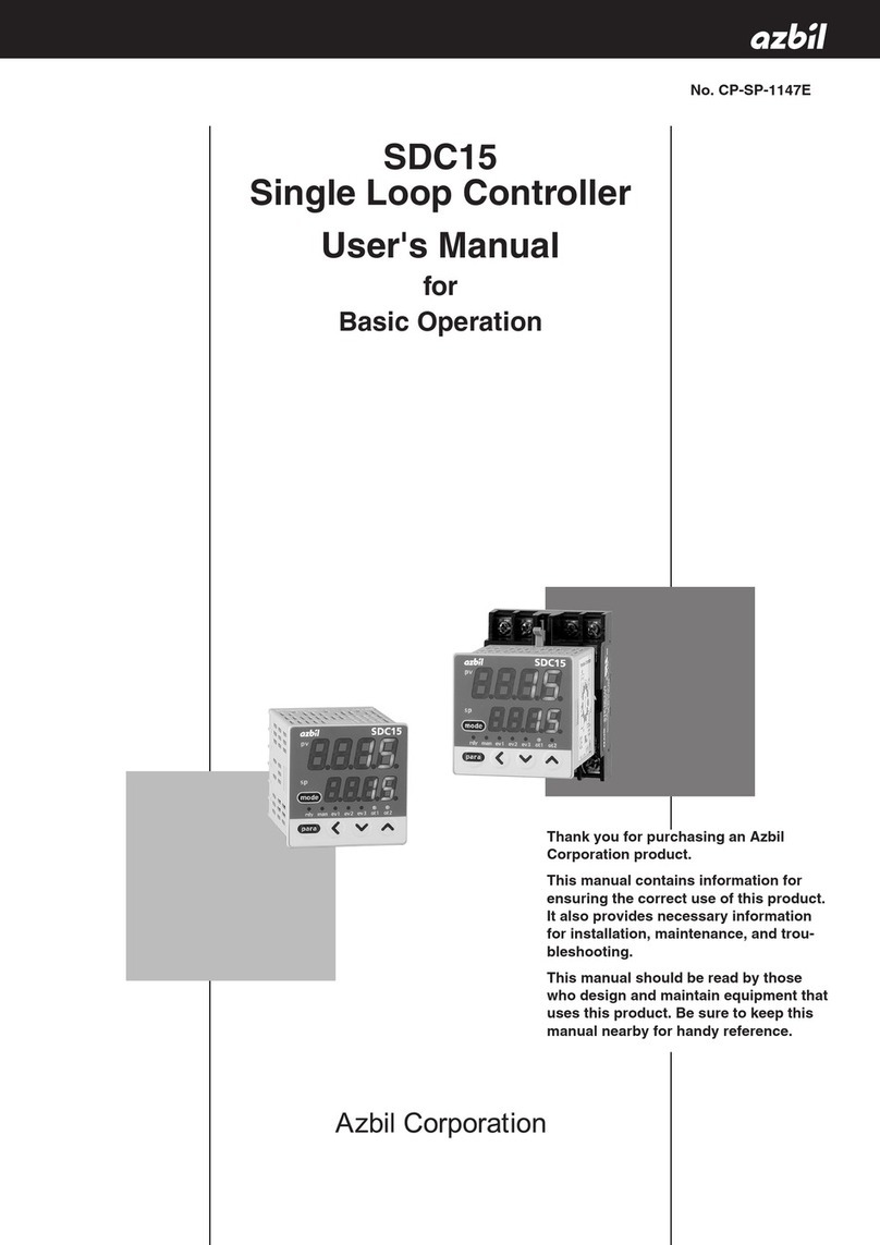
Azbil C15 User manual

Thank you for purchasing an Azbil
Corporation product.
This manual contains information for
ensuring the correct use of this product.
It also provides necessary information
for installation, maintenance, and
troubleshooting.
This manual should be read by those
who design and maintain equipment
that uses this product. Be sure to keep
this manual nearby for handy reference.
No. CP-SP-1147E
Single Loop Controller
Model C15
User’s Manual
for
Basic Operation
(Not for use in Japan)
NOTICE
Be sure that the user receives this manual before the product is used.
Copying or duplicating this user’s manual in part or in whole is forbidden.
The information and specifications in this manual are subject to change
without notice.
Considerable effort has been made to ensure that this manual is free from
inaccuracies and omissions. If you should find an error or omission, please
contact the azbil Group.
In no event is Azbil Corporation liable to anyone for any indirect, special or
consequential damages as a result of using this product.
© 2003–2020 Azbil Corporation. All Rights Reserved.
Modbus™ is a trademark and the property of Schneider Electric SE, its subsidiaries /
and affiliated companies.
i
To reduce the risk of an electric shock that could cause personal injury,
follow all safety notices in this document.
This symbol warns the user of a potential shock hazard where hazardous
live voltages may be accessible.
If the equipment is used in a manner not specified by the manufacturer, the protection provided by the
equipment must be impaired.
Do not replace any component (or part) not explicitly specified as replaceable by your supplier.
All wiring must be in accordance with local norms and carried out by authorized and experienced personnel.
A switch in the main supply is required near the equipment.
Main power supply wiring requires a (T) 0.2 A, 250 V fuse(s) (IEC 127).
z EQUIPMENT RATINGS
Supply voltages: 100 to 240 V AC (operating power supply voltage 85 to 264 V AC)
Frequency: 50/60 Hz
Power consumption: 12 VA max.
z EQUIPMENT CONDITIONS
Do not operate the instrument in the presence of flammable liquids or vapors.
Operation of any electrical instrument in such an environment constitutes a safety hazard.
Temperature: 0 to 50 °C
Humidity: 10 to 90 %RH (no condensation)
Vibration: 2 m/s
2
(10 to 60 Hz)
Over-voltage category: Category II (IEC60364-4-443, IEC60664-1)
Pollution degree: 2
Installation location: Indoors
Altitude: 2000 m or less
z EQUIPMENT INSTALLATION
The controller must be mounted into a panel to limit operator access to the rear terminal.
Specifications of common mode voltage: The common mode voltages of all I/O except for main
supply and relay outputs are less than 30 Vrms, 42.4 V peak and 60 V DC.
z APPLICABLE STANDARDS
EN61010-1,
EN61326-1 (For use in industrial locations)
During EMC testing, the reading or output may fluctuate by ±10 %FS.
Safety Requirements
ii
The safety precautions explained in the following section aim to prevent injury to the operator and others, and to
prevent property damage.
WARNING Warnings are indicated when mishandling this product
might result in death or serious injury.
CAUTION Cautions are indicated when mishandling this product
might result in minor injury to the user, or only physical
damage to the product.
In describing the product, this manual uses the icons and conventions listed below.
Use caution when handling the product.
The indicated action is prohibited.
Be sure to follow the indicated instructions.
Handling Precautions:
Handling Precautions indicate items that the user should pay attention to when handling
this device.
: This indicates the item or page that the user is requested to refer to.
Note: Notes indicate information that might benefit the user.
(1) (2) (3): Numbers within the parenthesis indicate steps in a sequence or parts in an explanation.
[para], [mode] etc.:These indicate keys on the keyboard of this unit, and messages and menus that appear
on the personal computer screen.
>>
: Indicates the result of an operation or the status after operation.
Conventions Used in This Manual
iii
z Numeric value and character display on LED
Numeric values The 7-segment LED expresses numeric values as follows:
0 1 2 3 4
5 6 7 8 9
Alphabetical characters The 7-segment LED expresses alphabetical characters shown below. There are
some alphabetical characters, which are not displayed on the LED.
A B C D E
abcde
F G H I J
f g h i j
K L M N O
k l m n o
P Q R S T
p q r s t
U V Y Z –
u v y z
Handling Precautions
As shown above, numeric value“2” and alphabetic character “Z” are shown
in the same manner.
Accordingly, numeric value “5” and alphabetic character “S”, as well as
numeric value “9” and alphabetic character “Q” are also shown in the same
manner.
iv
Safety Precautions
WARNING
Do not use this device in an environment with conductive pollution, or with dry non-
conductive pollution which can become conductive due to condensation, etc.
Otherwise, problems such as tracking phenomena may damage parts, resulting in fire.
When wiring the power for this device, be sure to mount a shutoff switch for the main power
to this unit within reach of the operator.
In addition, when wiring the power for AC power models, install a time-lag (T) fuse (rated
current 0.2 A, rated voltage 250 V) as specified by IEC 127.
Otherwise, tracking phenomena or parts failure due to other factors may cause fire.
Do not disassemble this device.
Doing so might cause electric shock or faulty operation.
Before removing, mounting, or wiring this device, be sure to turn off the power to the device
and all connected devices. Failure to do so might cause electric shock.
Do not touch electrically charged parts such as the power terminals.
Doing so might cause electric shock.
CAUTION
Use this device within the operating ranges recommended in the specifications (temperature,
humidity, voltage, vibration, shock, mounting direction, atmosphere, etc.).
Do not block ventilation holes.
Doing so might cause fire or faulty operation.
Wire this device properly according to predetermined standards.
Also wire the device using specified power leads according to recognized installation
methods. Failure to do so might cause electric shock, fire or faulty operation.
Do not allow lead clippings, metal shavings or water to enter the controller case.
Doing so might cause fire or faulty operation.
Firmly tighten the terminal screws at the torque listed in the specifications.
Insufficient tightening of terminal screws might cause electric shock or fire.
Do not use unused terminals on this device as relay terminals.
Doing so might cause electric shock, fire, or faulty operation.
We recommend attaching the terminal cover (sold separately) after wiring this device.
Failure to do so might cause electric shock, fire, or faulty operation.
Use the relays within the recommended life.
Failure to do so might cause fire or faulty operation.
If there is a risk of a power surge caused by lightning, use a surge absorber (surge protector)
to prevent fire or device failure.
Do not make incorrect connections. If the cables are connected incorrectly, this might cause
the unit to malfunction.
The controller does not function for approximately 6 s. after the power has been turned
ON. Great care should be taken if the relayoutput from the controller is used as an interlock
signal.
v
CAUTION
There is no isolation between control outputs 1 and 2. When necessary, use an appropriate
isolator.
Do not connect multiple loader cables to multiple units from one personal computer. The
current coming from other circuits might cause an error in the indication of the PV.
When wiring RS-485 communications, do not connect a terminating resistor to either end of
the communication path. A terminating resistor might cause a communication failure.
Do not operate the keys with a mechanical pencil or other sharp-tipped object.
Doing so might cause faulty operation.
In addition to ON/OFF control and conventional PID control, this unit is equipped with self-
tuning control, which does not require manual setting of control constants. Self-tuning
control ensures stable control even after a change in the SP or an external disturbance. This
is achieved by monitoring the control target, learning its characteristics, and automatically
calculating control constants.
Before Using This Unit
The protective film is adhered to the front console of this unit to protect the surface.
After the installation and wiring work has been completed, stick a scotch tape to the corner of the console and pull it
out in the direction indicated by an arrow to peel off the protective film.
Handling Precautions
If you attempt to peel off the protective film with your fingernail, this might
cause damage to the console.
ot2
ot1
ev3
ev2
ev1
man
rdy
para
mode
Scotch tape
Pull out.
vi
Five different manuals in total are available for model C15 Single Loop Controller (hereafter referred to as“this unit”).
Read appropriate manuals according to your requirements. If you do not have a required manual, contact the azbil
Group or its dealer. Additionally, you can download necessary manuals from “http://www.azbil.com”.
The user level of this unit can be selected from three levels, “Simple configuration”, “Standard configuration”, and
“High function configuration”. This manual describes the functions you can set up only with “Simple configuration”.
If more advanced application is needed, refer to Single Loop Controller Model C15 User’s Manual for Installation &
Configuration (CP-SP-1148E).
Single Loop Controller Model C15 User’s Manual for Basic Operation
Manual No. CP-SP-1147E
This manual. This manual is optional (sold separately). The manual describes the
functions you can set up only with “Simple configuration”. Personnel in charge of design,
manufacture, operation, and/or maintenance of a system using this unit must thoroughly
read this manual. This manual describes the installation, wiring, major functions and
settings, operating procedures, troubleshooting, and detailed specifications.
Single Loop Controller Model C15 User’s Manual for Installation
Manual No. CP-UM-5287E
This manual is supplied with the product. Personnel in charge of design and/
or manufacture of a system using this unit must thoroughly read this manual.
This manual describes the safety precautions, installation, wiring, and primary
specifications. For further information about operation, refer to other manuals,
Basic Operation and/or Installation & Configuration.
Single Loop Controller Model C15 User’s Manual for Installation & Configuration
Manual No. CP-SP-1148E
This manual is optional (sold separately). The manual describes the hardware and all
functions of this unit. Personnel in charge of design, manufacture, operation, and/
or maintenance of a system using this unit and those in charge of communication
software of a system using the communication functions of this unit must thoroughly
read this manual. This manual also describes the installation, wiring, connections
for communication, all functions and settings of this unit, operating procedures,
communication with host station, such as personal computer, communication
addresses, troubleshooting, and detailed specifications.
User’s Manual for Smart Loader Package Model SLP-C35 for Single Loop
Controller Model C15/25/26/35/36 Manual No. CP-UM-5290E
This manual is supplied with the Smart Loader Package. The manual describes
the software used to make various settings for C15/25/26/35/36 using a
personal computer. Personnel in charge of design or setting of a system using
C15/25/26/35/36 must thoroughly read this manual. The manual describes
installation of the software into a personal computer, operation of the personal
computer, various functions, and setup procedures.
CP-SP-XXXXE
Quick Reference Guide
for Model XXX
Quick Reference Guide for Model C15
Manual No. CP-UM-1213E
For those using this device for the first time or for operators on the work site, this
guide serves as a reference when setting or modifying parameters. Key operations,
menu flowcharts and parameter settings are presented with color illustrations.
The Role of This Manual
vii
This manual is organized as follows.
Chapter 1. OVERVIEW
This chapter describes the applications, features, model selection guide, and part
names and functions of this unit. Since the part names described in this chapter are
used in the subsequent descriptions, the part names and functions of this unit must
be understood correctly in this chapter.
Chapter 2. OUTLINE OF FUNCTIONS
This chapter describes the outline and operation flow of the functions of this unit.
Chapter 3. INSTALLATION
This chapter describes the environmental conditions, installation dimensions,
installation procedures, and necessary tools when installing this unit.
Chapter 4. WIRING
This chapter describes the wiring procedures, wiring precautions, and connection
examples.
Chapter 5. SETTINGS BEFORE STARTING OPERATION
This chapter describes the items necessary to set up before starting operation and
setting procedures.
Chapter 6. SETTINGS DURING OPERATION
This chapter describes the setting items and setting procedures when performing
the control with this unit built-into the customer’s system.
Chapter 7. LIST OF SIMPLE CONFIGURATION DISPLAY ITEMS
This chapter shows the list of the setting items when operating this unit with
“Simple configuration”.
Chapter 8. PID CONTROL TUNING
This chapter describes the auto tuning function and self-tuning function of this
unit.
Chapter 9. MAINTENANCE AND TROUBLESHOOTING
This chapter describes the maintenance and inspection of this unit, as well as
troubleshooting.
Chapter 10. DISPOSAL
This chapter describes safety precautions and how to dispose of this unit when the
unit is no longer used.
Chapter 11. SPECIFICATIONS
This chapter describes the general specifications, performance specifications, and
optional parts of this unit.
Organization of This User’s Manual
ix
Contents
Safety Requirements
Conventions Used in This Manual
Safety Precautions
Before Using This Unit
The Role of This Manual
Organization of This User’s Manual
Chapter 1. OVERVIEW 1-1
1 - 1 Overview 1-1
 Model selection table 1-2
 Accessories 1-3
 Optional parts 1-3
1 - 2 Part Names and Functions 1-4
 Main unit and console 1-4
 Bottom panel 1-5
 Rear panel 1-6
Chapter 2. OUTLINE OF FUNCTIONS 2-1
2 - 1 Input/Output Configuration 2-1
2 - 2 Key Operation 2-2
 Data setting procedures 2-3
 [mode] key operating procedures 2-4
 User level 2-5
2 - 3 Operation Modes 2-6
Chapter 3. INSTALLATION 3-1
 Installation place 3-1
 External dimensions 3-2
 Panel cutout dimensions 3-2
 Mounting procedures 3-3
Chapter 4. WIRING 4-1
4 - 1 Wiring 4-1
 Terminal assignment label symbols 4-2
 Wiring precautions 4-2
 Connection of open collector output to digital input 4-5
 Connection of communication (RS-485) cable 4-5
 Connection with solid state relay (SSR) 4-7
 Connection with current-input type controllers 4-10
 Noise preventive measures 4-10
4 - 2 Recommended Cables 4-11
x
Chapter 5. SETTINGS BEFORE STARTING OPERATION 5-1
5 - 1 PV Input 5-2
 PV range type setup 5-2
 Temperature unit setup 5-4
 Decimal point position setup 5-5
 PV range low limit/high limit setup 5-6
5 - 2 Control 5-7
 Control method setup 5-7
 Control action (Direct/Reverse) setup 5-8
 Heat/Cool control selection setup 5-9
 Heat/Cool control dead zone setup 5-10
 LSP system group setup 5-12
5 - 3 Internal Event 5-13
 Event operation type setup 5-20
 Event Direct/Reverse, standby, and Event state at READY setup 5-21
 Event main setting setup 5-22
 Event sub-setting setup 5-23
 Event hysteresis setup 5-24
5 - 4 CT (Current Transformer) Input 5-25
 CT type setup 5-25
 CT output setup 5-26
 CT wait time before measurement setup 5-27
5 - 5 Continuous Output 5-28
 Output range setup 5-28
 Output type setup 5-29
 Output scaling low limit/high limit setup 5-30
 MV scaling range 5-31
5 - 6 Communication 5-32
 Communication mode setup 5-32
 Station address setup 5-33
 Transmission speed setup 5-34
 Data format (data length) setup 5-35
 Data format (parity) setup 5-36
 Data format (stop bit) setup 5-37
5 - 7 Key Operation 5-38
 Mode key function setup 5-38
 User level setup 5-39
5 - 8 DI Assignment 5-40
 Internal contact operation type setup 5-40
Chapter 6. SETTINGS DURING OPERATION 6-1
6 - 1 SP 6-1
 SP setup in operation display mode 6-1
 LSP No. setup 6-2
 SP setup in parameter setting display mode 6-3
xi
6 - 2 Operation Display other than SP 6-4
 MV (manipulated variable) display and setup 6-4
 Heat MV (manipulated variable) and cool MV (manipulated variable) display 6-5
 AT (auto tuning) progress display 6-5
 CT (current transformer) input 1/2 current value display 6-6
6 - 3 Mode 6-7
 AUTO/MANUAL mode selection setup 6-7
 RUN/READY mode selection setup 6-8
 AT (auto tuning) Stop/Start selection setup 6-9
 Release all DO (digital output) latches setup 6-10
 Communication DI (digital input) 1 setup 6-11
6 - 4 PID 6-12
 P-1 (proportional band) setup 6-12
 I-1 (Integration time) setup 6-13
 d-1 (Derivative time) setup 6-14
 rE-1 (Manual reset) setup 6-15
 P-1C (Cool-side proportional band) setup 6-16
 I-1C (Cool-side integration time) setup 6-17
 d-1C (Cool-side derivative time) setup 6-18
6 - 5 Other Parameter Setup 6-19
 ON/OFF control differential setup 6-19
 PV filter setup 6-20
 PV bias setup 6-21
 Time proportional cycle 1/2 setup 6-22
 MV low limit/high limit at AT (auto tuning) 6-23
 AT type setup 6-24
 Key lock setup 6-25
 Password lock function 6-26
 Password display setup 6-27
 Passwords (1A, 2A, 1B, 2B) setup 6-28
Chapter 7. LIST OF SIMPLE CONFIGURATION DISPLAY ITEMS 7-1
7 - 1 List of Operation Displays 7-1
7 - 2 List of Parameter Setting Displays 7-2
7 - 3 List of Setup Setting Displays 7-5
Chapter 8. PID CONTROL TUNING 8-1
8 - 1 AT (auto tuning) Function 8-2
 Starting procedures 8-2
 Stopping procedures 8-2
8 - 2 ST (Self-tuning) Function 8-4
 Starting procedures 8-4
 Stopping procedures 8-5
8 - 3 Precautions for ST (Self-tuning) 8-6
xii
Chapter 9. MAINTENANCE AND TROUBLESHOOTING 9-1
 Maintenance 9-1
 Alarm display and corrective action 9-1
 Operation in case of PV input failure 9-2
Chapter 10. DISPOSAL 10-1
Chapter 11. SPECIFICATIONS 11-1
 Specifications 11-1
 Accessories 11-5
 Optional parts 11-5
Appendix App.-1
 Glossary App.-1
Index
1-1
Chapter 1. OVERVIEW
1-1 Overview
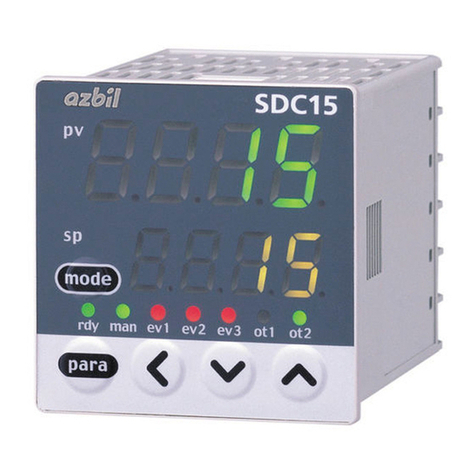
This unit is a compact controller having a mask of 48 × 48 mm and provides the following features:
• The depth is only 60 mm, providing the excellent space-saving.
• The front panel is only 2 mm thick. This ensures the excellent thin design.
• The display panel is large. This provides excellent visibility.
• [mode] key, [para] key, and digit-shift keys are provided on the front panel. This
ensures easy setup operation.
• Various input types are available, thermocouples (K, J, E, T, R, S, B, N, PLII,
WRe5-26, PR40-20, DIN U, DIN L), RTDs (Pt100, JPt100), current signals
(4 to 20mA DC, 0 to 20mA DC), and voltage signals (0 to 1V DC, 1 to 5V DC,
0 to 5V DC, and 0 to 10V DC).
• For control outputs, relay, voltage pulse, and current output are provided.
Additionally, these control outputs can be combined for the 2nd control output.
• The unit can be made applicable to the heat/cool control using the 2nd control
output and/or event relay.
• ON/OFF control, fixed PID, and self-tuning control can be performed.
• In addition to the PID control, two algorithms, RationaLOOP and Just-FiTTER,
are mounted. This ensures excellent controllability.
• With optional functions, a combination among 3- or 2-event points (independent
contacts), 2-point CT input, 2-point digital input, and/or RS-485 can be selected.
• The personal computer loader port is provided as standard function. The setup
can be made easily with use of the personal computer loader.
• Use of optional Smart Loader Package (SLP-C35) makes it possible to easily
perform the read/write operation of the parameters.
In addition to the table format setup, the operation and control status can be
monitored using the trend display. This unit can be operated without use of
program on the host unit.
• The unit is applicable to the IEC directive and the CE marking is put on the unit.
(Applicable standards: EN61010-1 and EN61326-1)
1-2
Chapter 1. OVERVIEW
 Model selection table
The following shows the model selection table of this unit:
Basic
model No.
Mounting Control
output
PV input Power
supply
Option Additional treatment Specifications
1 2
C15
T Panel mount type
*1S Socket mount type
Control output 1 Control output 2
*2R0 Relay contact output
NO
None (relay output for
control output 1: NC)
V0 Voltage pulse output
(for SSR drive)
None
*3VC Voltage pulse output
(for SSR drive)
Current output
*3VV Voltage pulse output
(for SSR drive)
Voltage pulse output
(for SSR drive)
C0 Current output None
*3CC Current output Current output
T Thermocouple input (K, J, E, T, R, S, B, N, PL II,
WRe5-26, PR40-20, DIN U, DIN L)
R RTD input (Pt100/JPt100)
L
DC voltage/DC current input (0 to 1 V DC,
1 to 5 V DC, 0 to 5 V DC, 0 to 10 V DC,
0 to 20 mA DC, 4 to 20 mA DC)
A AC Model (100 to 240 V AC)
D DC Model (24 V AC/24 to 48 V DC)
00 None
01 Event relay output: 3 points
*3*402 Event relay output: 3 points
Current transformer input: 2 points
Digital input: 2 points
*3*403 Event relay output: 3 points
Current transformer input: 2 points
RS-485 communication
*504 Event relay output: 2 points
(independent contact)
*3*4*505 Event relay output: 2 points
(independent contact)
Current transformer input: 2 points
Digital input: 2 points
*3*4*506 Event relay output: 2 points
(independent contact)
Current transformer input: 2 points
RS-485 communication
0 No additional processing
D Inspection Certificate provided
*1 Socket sold separately Y Complying with the traceability certification
*2 Only 1a contact is applicable for C15S 0 None
*3 Can not be selected for the C15S. A UL-marked product
*4 Current transformer sold separately
*5 Can not be selected for the DC Model.
1-3
Chapter 1. OVERVIEW
 Accessories
Name Model No.
Mounting bracket (for C15T) 81409651-001
Gasket 81409657-001
 Optional parts
Name Model No.
Mounting bracket (for C15T) 81446403-001
Gasket (20 pcs) 81406918-001
Current transformer (800 turns, 5.8mm hole dia.) QN206A*
Current transformer (800 turns, 12mm hole dia.) QN212A*
Socket (for C15S) 81446391-001
Hard cover 81446442-001
Soft cover 81446443-001
Terminal cover 81446898-001
Smart Loader Package SLP-C35J50
L-shaped plug adaptor 81441057-001
* Not UL-certified.
1-4
Chapter 1. OVERVIEW
 Main unit and console
ot2
ot1
ev3
ev2
ev1
man
rdy
para
mode
Main bodyConsole
rdy man ev1 ev2 ev3 ot1 ot2
para
mode
pv
sp
Lower Display
Mode indicator
[<], [ ], and [ ] keys
<
<
[para] key
Upper display
[mode] key
Console
SDC15
Main unit: Contains the electric circuit for I/O signals of measuring instruments,
CPU, and memory.
Console: Contains the display panel showing numeric value and status, and
operation keys.
z Detailed description of console
[mode] key
When this key is kept pressed for 1 s or longer in the operation display mode, any
of the following operations, which have been set previously, can be performed:
• AUTO/MANUAL mode selection
• RUN/READY mode selection
• AT (Auto Tuning) start/stop selection
• LSP (Local SP) group selection
• Release all DO (Digital Output) latches
• ON/OFF selection of communication DI (Digital Input) 1
When pressing the [mode] key in the setup display mode, the display is changed
to the operation display.
[para] key
This key is used to change the display item.
When this key is kept pressed for 2 s or longer in the operation display mode, the
display is then changed to the setup display.
[<], [
<
], [
<
]keys
These keys are used to increase or decrease the numeric value, or to shift the
digit.
1-2 Part Names and Functions
1-5
Chapter 1. OVERVIEW
Upper display
This display shows the PV value or the name of each display item (display value
or set value). If an alarm occurs in the operation display mode, the normal
display and alarm code are displayed alternately.
The decimal point at the right end digit shows AT (auto tuning) or ST (self-
tuning) status. The decimal point flashes twice repeatedly during execution of
AT while it flashes once repeatedly during execution of ST.
Lower display
This display shows the SP value, or the display value or set value of each display
item. The decimal point at the right end digit shows the communication status.
Mode indicators
[rdy]: RUN/READY mode indicator. Lights when READY
[man]: AUTO/MANUAL mode indicator. Lights when MANUAL
[ev1], [ev2], [ev3]:
Event output 1 to 3 indicator. Lights when event relays are ON.
[ot1], [ot2]: Control output 1 and 2 indicator. Lights when the control
output is ON. The indicators are always lit when the current
output is used.
Handling Precautions
• To select the LSP group using the [mode] key, it is necessary to set a value
of “2” or more in [LSP system group].
• To show the communication status using the decimal point at the right
end digit on the lower display, select “High function configuration” and
make the [LED monitor] settings.
• Do not operate the key with a sharp object (such as tip of mechanical
pencil or needle). Doing so might cause the unit to malfunction.
 Bottom panel
Loader connector
Loader connector: This connector is connected to a personal computer using the
dedicated cable supplied with the Smart Loader Package.
1-6
Chapter 1. OVERVIEW
 Rear panel
z Model C15T (Panel mount type)
Terminal part
Terminal part: The power supply, input, and output are connected to the terminals.
The M3 screw is used. When connecting to the terminal, always use
a correct crimp terminal suitable for the M3 screw.
The tightening torque of the terminal screw is 0.4 to 0.6 N·m.
z Model C15S (Socket mount type)
Socket part
Socket part: This socket is inserted into the optional socket. The power supply,
input, and output are connected from the socket.
When performing the wiring from the socket, always use a correct
crimp terminal suitable for the M3.5 screw.
The tightening torque of the socket terminal screw is 0.78 to 0.98 N·m.

Other manuals for C15

2

This manual suits for next models

1

Other Azbil Controllers manuals

Azbil Infilex BC WY5610 User manual

Azbil

Azbil Infilex BC WY5610 User manual

Azbil KFPA User manual

Azbil

Azbil KFPA User manual

Azbil AB-7352-U User manual

Azbil

Azbil AB-7352-U User manual

Azbil C25 User manual

Azbil

Azbil C25 User manual

Azbil C36 User manual

Azbil

Azbil C36 User manual

Azbil C15M User manual

Azbil

Azbil C15M User manual

Azbil dcp551 mark II User manual

Azbil

Azbil dcp551 mark II User manual

Azbil Infilex VC User manual

Azbil

Azbil Infilex VC User manual

Azbil Micro Flow MQV9020 User manual

Azbil

Azbil Micro Flow MQV9020 User manual

Azbil Azbil MIZCON Plus User manual

Azbil

Azbil Azbil MIZCON Plus User manual

Azbil F4Q User manual

Azbil

Azbil F4Q User manual

Azbil SLPC1F User manual

Azbil

Azbil SLPC1F User manual

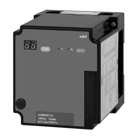
Azbil AUR890 Series User manual

Azbil

Azbil AUR890 Series User manual

Azbil MPC0002 User manual

Azbil

Azbil MPC0002 User manual

Azbil C7G Manual

Azbil

Azbil C7G Manual

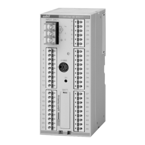
Azbil Infilex AC WY5117C1 Series User manual

Azbil

Azbil Infilex AC WY5117C1 Series User manual

Azbil Infilex ZM WY5122 User manual

Azbil

Azbil Infilex ZM WY5122 User manual

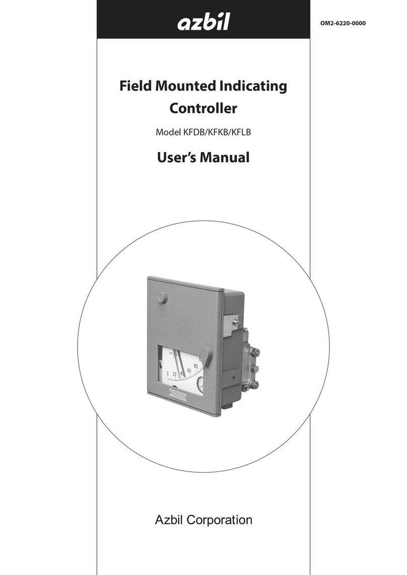
Azbil KFDB User manual

Azbil

Azbil KFDB User manual

Azbil C15 User manual

Azbil

Azbil C15 User manual

Azbil C1M User manual

Azbil

Azbil C1M User manual

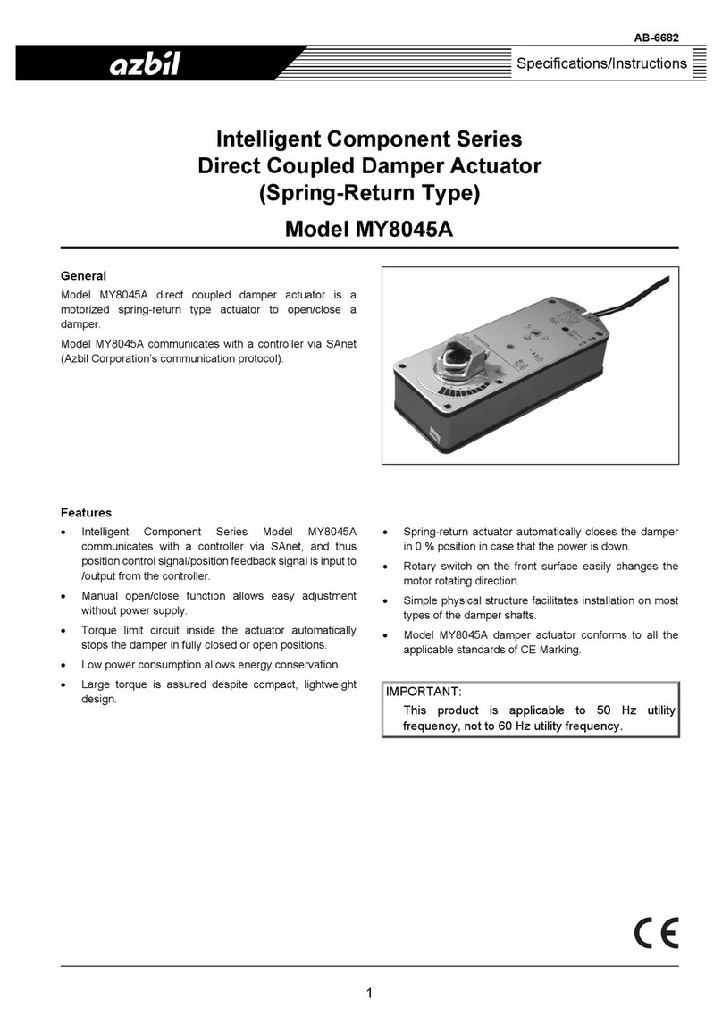
Azbil MY8045A User manual

Azbil

Azbil MY8045A User manual

Azbil RA1B User manual

Azbil

Azbil RA1B User manual

Azbil F4Q User manual

Azbil

Azbil F4Q User manual

Azbil C35 User manual

Azbil

Azbil C35 User manual

Popular Controllers manuals by other brands

Bodine GTD10DIM installation instructions

Bodine

Bodine GTD10DIM installation instructions

AirStage UTY-DTGYZ1 installation manual

AirStage

AirStage UTY-DTGYZ1 installation manual

Eskon EPA 200 user manual

Eskon

Eskon EPA 200 user manual

Comunello Automation EAGLE Installation and user manual

Comunello Automation

Comunello Automation EAGLE Installation and user manual

Siemens CPU 410-5H Process Automation System manual

Siemens

Siemens CPU 410-5H Process Automation System manual

Lumatek LUMBC006 manual

Lumatek

Lumatek LUMBC006 manual

Dover Petro Vend FSC3000 installation manual

Dover

Dover Petro Vend FSC3000 installation manual

BIFFI GIGS 0.3 Use and maintenance manual

BIFFI

BIFFI GIGS 0.3 Use and maintenance manual

TMS LC-18-OD-4CH-48V user manual

TMS

TMS LC-18-OD-4CH-48V user manual

Serato DJ INTRO NUMARK MIXTRACK PRO quick start guide

Serato

Serato DJ INTRO NUMARK MIXTRACK PRO quick start guide

3M Touch Screen Controller RX181 reference guide

3M

3M Touch Screen Controller RX181 reference guide

Vimar 03905 manual

Vimar

Vimar 03905 manual

Full Gauge Controls MT-530 Super manual

Full Gauge Controls

Full Gauge Controls MT-530 Super manual

McQuay MicroTech III Installation and maintenance manual

McQuay

McQuay MicroTech III Installation and maintenance manual

Delem DA-52s Reference manual

Delem

Delem DA-52s Reference manual

Hanna Instruments BL 983320-0 user manual

Hanna Instruments

Hanna Instruments BL 983320-0 user manual

Disaster Area Designs DMC.micro user manual

Disaster Area Designs

Disaster Area Designs DMC.micro user manual

YASKAWA PROFINET 1000 Series Technical manual

YASKAWA

YASKAWA PROFINET 1000 Series Technical manual

manuals.online logo
manuals.online logoBrands
  • About & Mission
  • Contact us
  • Privacy Policy
  • Terms and Conditions

Copyright 2025 Manuals.Online. All Rights Reserved.