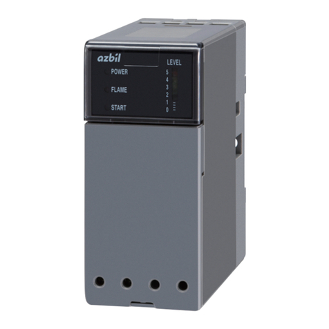
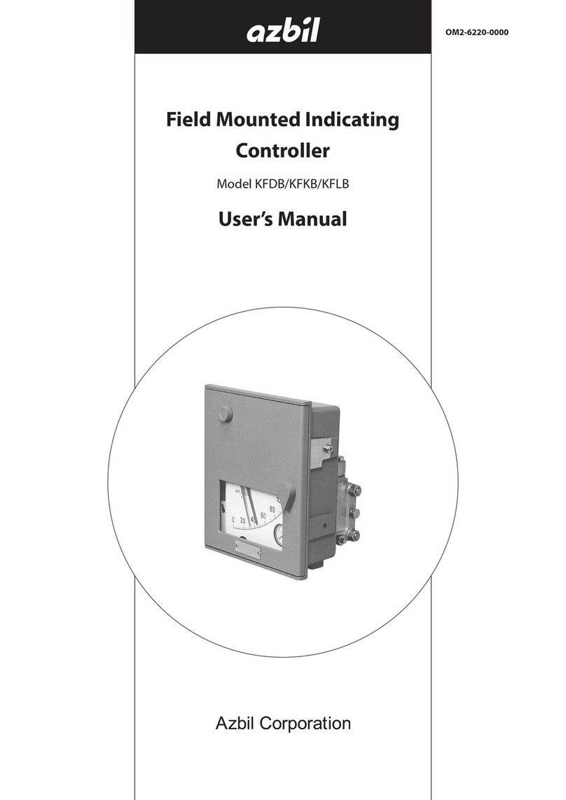
Azbil RA890G User manual

Thank you for purchasing the RA890G
PROTECTORELAY Burner Controller.
This manual contains information for ensur-
ing the correct use of the RA890G. It also
provides necessary information for installa-
tion, maintenance, and troubleshooting.
This manual should be read by those who
design and maintain equipment that uses
the RA890G. Be sure to keep this manual
nearby for handy reference.
No. CP-UM-1218E
RA890G
PROTECTORELAY
Burner Controller
User's Manual

NOTICE
Be sure that the user receives this manual before the product is used.
Copying or duplicating this user’s manual in part or in whole is forbidden. The
information and specifications in this manual are subject to change without
notice.
Considerable effort has been made to ensure that this manual is free from
inaccuracies and omissions. If you should find an error or omission, please
contact the azbil Group.
In no event is Azbil Corporation liable to anyone for any indirect, special or
consequential damages as a result of using this product.
© 1984-2013 Azbil Corporation All Rights Reserved.

i
Conventions Used in This Manual
To prevent injury to the operator and others, and to prevent property damage, the following types of safety■
precautions are indicated:
In describing the product, this manual uses the icons and conventions listed below.■
Use caution when handling the product.
The indicated action is prohibited.
Be sure to follow the indicated instructions.
Handling Precautions:
Handling Precautions indicate items that the user should pay attention to when handling
the RA890G.
Note: Notes indicate information that might benefit the user.
This indicates the item or page that the user is requested to refer to.
(1), (2), (3): Numbers within parentheses indicate steps in a sequence or parts of an explanation.
WARNING Warnings are indicated when mishandling this product might result in
death or serious injury.
CAUTION Cautions are indicated when mishandling this product might result in
minor injury to the user, or physical damage to the product.

ii
Safety Precautions
Safety precautions are intended to ensure the safe and correct use of this product, to prevent injury to the operator and
others, and to prevent damage to property. Be sure to observe these safety precautions. Please make sure you under-
stand the safety guidelines before reading the rest of this manual.
The use of this product in a manner not specified by the manufacturer will impair its built-in safety features.
WARNING
Use this device for batch operation of the burner (at least one start and stop in a 24-hour period).
Do not use for continuous burner operation (nonstop combustion for 24h or longer).
This device performs recycle operation during flame failure. Therefore, when it is to be used together
with a gas-fired combustion system, operate it in non-recycle sequence by using an on-delay timer.
This device does not have the prepurge functions required for burner ignition. Give careful consider-
ation to various safety guidelines, etc., when setting timers and sequencing times.
Wire terminals 1 and 2 so that they receive power continuously whenever the power switch is turned
on. This is absolutely necessary to ensure operation of the self-check circuits at startup. Therefore, do
not wire a thermostat between the power switch and terminal 1 or 2. Doing so might cause a serious
combustion equipment accident.
Connect loads (ignition transformer, solenoid valve, etc.) directly to the output terminals of this de-
vice. If they are not directly connected, combustion safety cannot be ensured.
Do not allow the pilot or main burner ignition trial time to exceed the specifications of the burner or
equipment manufacturer. If they do, fuel may accumulate in the combustion chamber and form an
explosive air-fuel mixture, resulting in a serious explosion hazard.
Before wiring, mounting, or removing this device, be sure to turn the power off. Wiring with the
power on can result in an electric shock.
Do not connect a solenoid valve to the high voltage side of the circuit. If a ground fault occurs, the
ground fault current may energize and open the solenoid valve. This device will not be able to pre-
vent the valve from opening and fuel from flowing out.
Even after the power to this device is turned off, terminal F continues to hold an electrical charge.
To avoid electrical shock, do not touch terminal F.
Carry out the pilot turndown test. If the flame detector is set so that it detects a pilot flame that is
too small to ignite the main burner, this device will not be able to detect a flame failure in the main
burner. In that case, fuel will continue to be supplied, causing a serious explosion hazard.
Before the pilot turndown test or ignition spark response test, make sure that all manual fuel valves
are closed.
If the pilot turndown test must be carried out repeatedly, completely shut down all equipment each
time the test is finished, and completely discharge unburned gas or fuel that has accumulated in
the ducts and combustion chamber. Failure to discharge unburned gas or fuel may result in an
explosion.
When the pilot turndown test is complete, turn OFF the power switch to shut down the power.
Restore all test jumpers and limit interlock/regulator settings to their previous states. If operation
begins without the above steps, damage to the equipment, gas leak or explosion may result.
Do not start regular operation of the equipment without first completing the trial-run adjustments
for this device, as well as the tests specified by the equipment manufacturer.
iii
WARNING
If lockout occurs, be sure to remove the cause of the lockout and reset it. Also, be sure to do a pre-
purge before restarting the system. If the combustion chamber and gas flue are not ventilated to
remove any unburned gas, the ignition process may cause an explosion.
To prevent electric shock, turn the power off and discharge any remaining electrical charge before
removing this device from the subbase. Use lead wires to connect terminals F and G of the flame
simulator (FSP300C100) to terminals F and G of this device for 10 seconds or more.
Do not touch this device's internal relay. Doing so might damage the relay or cause this device and/
or the combustion equipment to malfunction.
CAUTION
Use the RA890G for the oil-fired or gas-fired combustion equipment up to approx. 700 kW in com-
bustion rate.
Do not install where exposed to any of the following:
• Certain chemicals or corrosive gases (ammonia, sulfur, chlorine, ethylene compounds, acid, etc.)
• Splashing water or excessive humidity
• High temperatures
• Prolonged vibration
Make sure the load connected to each terminal does not exceed the rating indicated in the specifica-
tions.
If timers and auxiliary relays are needed for additional functions, select ones with high reliability, and
be sure to design the circuit correctly.
When installing and wiring, be sure to follow the instructions in this manual and in the user's manual
for the combustion equipment.
Do not detect ultraviolet rays other than those of the burner flame. If the flame detector responds to
other ultraviolet rays, it will report that there is a flame even if the burner flame goes out. As a result,
fuel will continue to be discharged, causing a very serious explosion hazard.
The ignition transformer ground lead should be connected directly to the burner body or to a metal-
lic part electrically connected to the burner body.
Connect the blue signal lead from the Minipeeper Ultraviolet Flame Detector to terminal F and the
white lead to terminal G. Turning on the power while the flame detector is incorrectly wired could
damage the UV tube.
A thermostat for low-voltage use is usually put between terminals T1 and T2.
Run the high-voltage ignition transformer cable separately and keep it at least 10 cm away from this
device.
Keep power lines and ignition transformer high-voltage cables separate from the flame detector
wires.
Make sure that ignition transformer high-voltage cables are properly connected to prevent faulty
contact. Faulty contact might generate high-frequency radio waves which can cause malfunction.

iv
CAUTION
Always connect the power supply last. Otherwise, touching a terminal accidentally could result in
electric shock or damage.
Always supply electric power at the voltage and frequency stated on the model label of this device.
In keeping with technical standards for electrical equipment, the burner body must have an earth
ground connection with a resistance of less than 100 Ω.
After the wiring is complete, be sure to check that it is correct. Incorrect wiring may cause damage
or faulty operation.
Make sure that the flame detector does not detect the ignition spark. If the flame detector can detect
the spark, change the position of the detector or the ignition electrode.
Only an experienced technician who has knowledge and technical skills related to combustion equip-
ment and combustion safety should carry out the pilot turndown test.
This product is equipped with functions that are extremely important for the safe operation of com-
bustion equipment. Carefully follow the instructions for its use that are given in this user's manual.
Do not use this device with the cover removed. Doing so might cause faulty operation.
Check the flame current at least once per month. Doing so can prevent shutdowns caused by a weak
flame current signal.
This device has an operating life. Assuming that the operating life of the combustion equipment
used with this device is longer, be sure to do periodic maintenance and replacement of this device.
In the event that this device is replaced, do all of the checks listed in chapter 4, INSPECTION AND
ADJUSTMENT.
When doing a maintenance inspection of the burner, be sure to do the pilot turndown test. Inspection
must be done at least once a year.
Conduct periodic inspections in accordance with the user's manual of the equipment manufac-
turer.
When cleaning the burner, clean the flame detector as well.

v
Contents
Conventions Used in This Manual
Safety Precautions
Chapter 1. OVERVIEW
Overview
■..........................................................
1
Features
■..........................................................1
System configuration
■................................................1
Security function and precautions for facility instrumentation
■................2
Names of parts
■.....................................................3
Chapter 2. MOUNTING
Mounting the subbase
■...............................................4
Mounting the RA890G onto the subbase
■.................................5
Chapter 3. WIRING
Non-recycling gas-fired combustion
■.....................................
7
Recycling oil-fired combustion (2-stage combustion)
■. . . . . . . . . . . . . . . . . . . . . . .12
Wiring the solenoid valve
■............................................
18
Wiring
■AUD100 series Advanced UV Sensors .............................18
Chapter 4.
INSPECTION AND ADJUSTMENT
Inspection
■........................................................
19
Ignition spark response test
■..........................................
22
Pilot turndown test
■.................................................
23
Safety shutdown checks
■.............................................
24
Chapter 5. MAINTENANCE
Maintenance and inspection intervals
■..................................25
Troubleshooting
■...................................................
26
Chapter 6. SPECIFICATIONS
Specifications
■.....................................................29
External dimensions
■................................................
30


1
Chapter 1. OVERVIEW
Overview■
The RA890G is an electronic burner controller to be used for the automatic opera-
tion and safety operation of gas, oil or combination gas-oil combustion equipment,
up to 700 kW in batch operation. And it is used combined with the AUD100 series
advanced ultraviolet flame detector. For combustion equipment in continuous
operation, use the AUR450C dynamic self-checking burner controller. This device
can configure a prepurge function using external instrumentation, and automati-
cally ignite pilot and main burners, and monitor the flame. The RA890G performs
recycle operation during flame failure.
Compatible burner
operation type
Purge
function
Ignition
function
Behavior if flame
failure occurs
Compatible flame
detector
Batch No Yes Recycle AUD 100 Series
Advanced Ultraviolet
Flame Detector
Features■
• If the burner fails in ignition, the safety switch is operated to shut off fuel
automatically.
• A safeguard circuit is incorporated to prevent the RA890G from being operated,
when the flame detector detects a false flame.
• When connected to temperature controllers, etc., the RA890G can automatically
start and stop combustion.
• A test jack is provided to permit the flame current to be read.
• Applicable to the intermittent pilot system.
• The RA890G is operated after mounted directly onto the Q270A subbase.
System configuration■
In terms of the overall system, the RA890G serves as the ignition controller and the
flame monitoring device. It is used as shown in the diagram below.
Air pressure
lower interlock
Gas pressure
lower interlock
Gas pressure
upper interlock
Ignition
transformer
Air
Fuel
MV MV
PV PV
T/C T/C
Temperature
controller
L
LH
High limit controller
Combustion
chamber
Combustion equipment
RA890G
PS
PS
IG
PS
Flame
detector
Exhaust

2
Chapter 1. OVERVIEW
Security function and precautions for facility instrumentation■
The RA890G is designed to ensure safety, and plays an important safety role by
monitoring the burner operation and the flame.
(1) Combustion monitoring and safety shutoff
• Detects flame failure in the burner and quickly shuts off the fuel and shuts
down the burner.
• When an ignition failure, flame failure or flame-out occurs, the RA890G fol-
lows a fixed sequence to stop each piece of equipment.
(2) Startup, operation, and shutoff of combustion equipment
• The RA890G operates each device according to the predetermined sequence
and timing.
(3) Safe startup
• At every startup signal, the RA890G checks for false flame in the flame detec-
tor and flame detection circuit.
• If a problem is detected, the RA890G does not start the burner.
(4) Redundant design
• Maintains safety even if its own self-check circuit fails.
• Will not deviate from the proper ignition sequence.
• The sequence timing is designed so that it is failsafe.
In designing facilities that use combustion safety devices, be sure to give careful
consideration to the safety guidelines listed below.
• For safety standards for industrial facilities using combustion equipment, see the
technical guidelines published by the Ministry of Health, Labour and Welfare.
• For general safety rules for industrial combustion furnaces, see JIS B 8415.
• For technical safety guidelines for gas combustion furnaces in industrial use, see
publications by the Japan Gas Association.
Important points for ensuring safety●
(1) Connect the load directly to the RA890G.
(2) Design the interlock so that it can directly cut off power to the load.
(3) Be sure to use a safe startup circuit upon startup.
(4) Do not set up a bypass, such as manual operation, for any load.
(5) Have a redundant main valve and pilot valve.
Precautions for system design●
• Since the RA890G does not have purge and ignition functions, they must be pro-
vided externally.
• To stop the recycle at flame failure, provide a timer circuit externally.

3
Chapter 1. OVERVIEW
Names of parts■
Terminal block
Q270A1024
Subbase
(sold separately)
Mounting base
Flame current
test jack
Safety switch
Cover retaining
screw
Safety switch
reset button
Cover
Flame relay
(2K)
Load relay
(1K)
Transformer 2
(TR2)
Transformer 1
(TR1)

4
Handling Precautions
Installation, wiring, inspection, adjustment, etc. should be carried out by a•
trained and experienced technician who has knowledge and technical skills
related to combustion equipment and flame safeguard control devices.
Mounting the subbase■
CAUTION
Do not install where exposed to any of the following:
• Certain chemicals or corrosive gases (ammonia, sulfur, chlorine, ethylene compounds, acid, etc.)
• Splashing water or excessive humidity
• High temperatures
• Prolonged vibration
When installing and wiring, be sure to follow the instructions in this manual and in the user's
manual for the combustion equipment.
Mounting method●
(1)
Mount the subbase as shown below, so that the three knockouts on the back are
in the lower part of the back, the top edge is horizontal, and the back is vertical.
The subbase may lean backward within 45 degrees if necessary.
(2) Open knockout holes for conduits as required, and attach wiring conduits there.
(3) Fix the subbase at the specified position with screws (3).
Horizontal
Vertical
ø22 Knockout
Mounting holes (3)
104.8
.
..
73
Maximum lean 45˚
OK OK
Chapter 2. MOUNTING

5
Chapter 2. MOUNTING
Mounting the RA890G onto the subbase■
Mount the RA890G onto the subbase after the completion of external wiring.
(1) Loosen the cover retaining screws and remove the cover from the RA890G.
(2) Set the position of the RA890G mounting base to that of the subbase.
(3) Tighten the terminal screws (10 pcs) of the RA890G securely in the individual
terminal thread holes in the subbase using 1 N·m tightening torque. (Electrical
connection with the subbase is completed when the RA890G is mounted.)
(4) Replace the cover to the RA890G.
Q270A subbase
RA890G mounting base
Cover retaining screw
Cover
Terminal screw holes (10)
Terminal screws (10 pcs): Tighten securely
Handling Precautions
The RA890G is connected electrically with a subbase by terminal screws.•
A loose terminal screw makes the RA890G malfunction. Be sure that there is
no loose terminal screw.

6
WARNING
The RA890G performs recycle operation during flame failure. Therefore, when it is to be used
together with a gas-fired combustion system, operate it in non-recycle sequence by using an on-
delay timer.
Wire terminals 1 and 2 so that they receive power continuously whenever the power switch is
turned on. This is absolutely necessary to ensure operation of the self-check circuits at startup.
Therefore, do not wire a thermostat between the power switch and terminal 1 or 2. Doing so might
cause a serious combustion equipment accident.
Connect loads (ignition transformer, solenoid valve, etc.) directly to the output terminals of this de-
vice. If they are not directly connected, combustion safety cannot be ensured.
CAUTION
Connect the blue signal lead from the Minipeeper Ultraviolet Flame Detector to terminal F and the
white lead to terminal G. Turning on the power when the flame detector is incorrectly wired could
damage the UV tube.
When installing and wiring, be sure to follow the instructions in this manual and in the user's man-
ual for the combustion equipment.
Make sure the load connected to each terminal does not exceed the rating indicated in the
specifications.
Always supply electric power at the voltage and frequency stated on the model label of this device.
If timers and auxiliary relays are needed for additional functions, select ones with high reliability,
and be sure to design the circuit correctly.
In keeping with technical standards for electrical equipment, the burner body must have an earth
ground connection with a resistance of less than 100 Ω.
Keep power lines and ignition transformer high-voltage cables separate from the flame detector
wires.
Run the ignition transformer high-voltage cable separately and keep it at least 10 cm away from this
device.
Always connect the power supply last. Otherwise, touching a terminal accidentally could result in
electric shock or damage.
Handling Precautions
Use a PVC insulated wire (such as IV (2 mm• 2) wire) with 600 Vac voltage proof
for each terminal.
For the terminals F and G, the allowable wiring length shall be 200 m or less.•
Chapter 3. WIRING

7
Chapter 3 WIRING
Non-recycling gas-fired combustion■
WARNING
In the case of gas-fired combustion equipment, do not connect the main valves to terminal 3.
If ignition failure occurs, the main valves would remain open and allow fuel to flow out until lockout
occurs, causing a serious hazard.
CAUTION
Give careful consideration to safety guidelines, etc., when setting timers.
Handling Precautions
Relay 1K has contacts 1K1 to 1K4 for the ignition transformer, pilot valves, and•
main valves. Relay 2K has contacts 2K1 to 2K4 for the flame detector.
In the case of gas-fired combustion equipment, be sure to connect an on-•
delay timer and auxiliary relay to disable recycling.
Wiring diagram●
Power supply
(H)
Power supply
(G)
Alarm
Main valve 1
TM1
TM1
TM
1
RA890G
Prepurge
completion
signal
Burner
start contacts
AUD100
Series Blue
White
F
G
1
6 5
4
3
2
2K
TR2
2K2
2K1
1K1
2K3
1K3
2K4
1K4
1K2
T2
T1
COM
SS1*2
R
1K SS2*2NC
NO
TR1
Safety switch
heater
Thermistor
Start check
circuit
Thermostat*1
(for low voltage)
Flame
detection
Ignition
transformer
Pilot valve 1
On delay
timer
TM1
103X
101
X
103
X
Blower on-o circuit / prepurge circuit
Limit/interlock circuit
(limit switch, interlock switch)
Main valve 2
Pilot valve 2
Thermostat*1
(for power supply)
*1 Use the thermostat for either the power supply or for low voltage.
*2 SS1 and SS2 are contacts for the safety switch heater. Design the circuit so that the blower on-off circuit/prepurge
circuit will always be reset if an alarm occurs (101X: ON).

8
Chapter 3 WIRING
Normal operation●
Input status RA890G operation Output status
Power ON Power is supplied to terminals 1 and 2, and voltage is applied to•
transformers TR1 and TR2.
Blower ON The blower turns on. When the prepurge ends, the prepurge com-•
pletion signal is generated to make the next process possible.
Burner start contacts
ON
Thermostat
(for low voltage) ON
If the limit and interlock conditions are normal (limit contacts are•
closed) and the burner start contacts are closed, power is supplied to
terminals 6 and 2, and voltage is applied to transformer TR1.
A start request from the thermostat closes the contacts between•
terminals T1 and T2, and current flows as follows: internal SS1 →
relay 1K → terminal T2 → thermostat (for low voltage) → terminal 1
→ thermistor → contacts 2K3 → safety switch heater.
When current flows to the thermistor, the thermistor's resistance•
declines, and 3 seconds later, relay 1K is energized.
When contacts 1K1 close, voltage is applied to terminal 4 to turn on•
the ignition transformer, and to terminal 3 so that the pilot valves
are opened and external timer TM1 starts.
Contacts 1K3 close and relay 1K forms a self-maintaining circuit.•
Since contacts 1K2 are closed, the thermistor stops heating, and the•
safety switch heater begins heating via contacts 2K3, 1K2, and 1K3.
Ignition transformer
starts
Pilot valves open
(TM1 starts)
The flame detector
detects a flame
If the flame detector senses a flame within the safety switch's lock-•
out time (about 15 seconds), relay 2K is energized.
When contacts 2K1 open, voltage to terminal 4 is cut off, and igni-•
tion transformer operation stops.
When contacts 2K2 close, voltage is applied to terminal 5, and exter-•
nal relay 103X turns on.
When the time set for TM1 operation has passed and contacts TM1•
have turned on, the main valves open.
Contacts 2K3 open, and the safety switch heater stops heating.•
Ignition transformer
stops
(103X: ON)
(Contacts TM1: ON)
Main valves open
Thermostat
(for low voltage) OFF
When the thermostat ends its start request, the contacts between•
terminals T1 and T2 open, relay 1K turns off, contacts 1K1, 1K2, and
1K3 open, and contacts 1K4 close.
Voltage to terminals 3, 4, and 5 stops, and all loads stop operation.•
The RA890G returns to the initial state and is ready for the next re-•
quest from the thermostat (for low voltage).
Pilot valves close
(103X: OFF)
Main valves close
(TM1 stopped)
Limit & interlock
Burner start contacts ON
Thermostat (for low voltage) ON
Blower ON
Prepurge
Prepurge completion signal
TM1
on-delay time
Thermostat (for low voltage) OFF
Blower OFF
Start check (appox. 3s)
Blower ON
Elapsed time
Ignition transformer
Pilot valve
Alarm
Main valves
Burner start contacts
Power ON
Flame detection

9
Chapter 3 WIRING
WARNING
If lockout occurs, be sure to do a prepurge before restarting the system. If the combustion chamber
and flue are not ventilated to remove accumulated unburned gas, the ignition process may cause an
explosion.
Handling Precautions
Even if the on-delay timer is set to more than 15 s, the ignition transformer•
stops after the lockout time of 15 s.
Ignition failure●
Input status RA890G operation Output status
Power ON Power is supplied to terminals 1 and 2, and voltage is applied to•
transformer TR2.
Blower ON The blower turns on. When the prepurge ends, the prepurge com-•
pletion signal is generated to make the next process possible.
Burner start contacts
ON
Thermostat
(for low voltage) ON
If the limit and interlock conditions are normal (limit contacts are•
closed) and the burner start contacts are closed, power is supplied to
terminals 6 and 2, and voltage is applied to transformer TR1.
A start request from the thermostat closes the contacts between•
terminals T1 and T2, and current flows as follows: internal SS1 →
relay 1K → terminal T2 → thermostat (for low voltage) → terminal 1
→ thermistor → contacts 2K3 → safety switch heater.
When current flows to the thermistor, the thermistor's resistance de-•
clines, and 3 seconds later, relay 1K is energized.
When contacts 1K1 close, voltage is applied to terminal 4 to turn on•
the ignition transformer, and to terminal 3 so that the pilot valves are
opened and external timer TM1 starts.
Contacts 1K3 close and relay 1K forms a self-maintaining circuit.•
Since contacts 1K2 are closed, the thermistor stops heating, and the•
safety switch heater begins heating via contacts 2K3, 1K2, and 1K3.
Ignition transformer
starts
Pilot valves open
(TM1 starts)
Flame detector does
not detect a flame
within the safety
switch time
When the time set for TM1 has passed after the start of ignition•
transformer operation, voltage to the transformer is cut off, the
transformer ceases operation, and the pilot valves also close.
If the flame detector cannot detect a flame within the safety switch•
heater's lockout time (about 15 seconds), the heater is locked out,
contacts SS1 open, relay 1K turns off, contacts 1K1, 1K2, and 1K3
open, and contacts 1K4 close.
Voltage to terminals 3, 4, and 5 stops, and all loads stop operation.•
Also, contacts SS2 close and activate an alarm.
Ignition transformer
stops
Pilot valves close
(Contacts TM1: OFF)
(TM1 stopped)
Alarm
(101X: ON)
Power ON Lockout timing (appox. 15s)
on-delay time
TM1
Start check (appox. 3s)
Elapsed time
Limit & interlock
Blower ON
Prepurge
Prepurge completion signal
Ignition transformer
Pilot valve
Alarm
Main valves
Burner start contacts
Burner start contacts ON
Thermostat (for low voltage) ON
Blower ON

10
Chapter 3 WIRING
Flame failure during combustion●
Input status RA890G operation Output status
Power ON Power is supplied to terminals 1 and 2, and voltage is applied to•
transformer TR2.
Blower ON The blower turns on. When the prepurge ends, the prepurge com-•
pletion signal is generated to make the next process possible.
Burner start contacts
ON
Thermostat
(for low voltage) ON
If the limit and interlock conditions are normal (limit contacts are•
closed) and the burner start contacts are closed, power is supplied to
terminals 6 and 2, and voltage is applied to transformer TR1.
A start request from the thermostat closes the contacts between•
terminals T1 and T2, and current flows as follows: internal SS1 →
relay 1K → terminal T2 → thermostat (for low voltage) → terminal 1
→ thermistor → contacts 2K3 → safety switch heater.
When current flows to the thermistor, the thermistor's resistance de-•
clines, and 3 seconds later, relay 1K is energized.
When contacts 1K1 close, voltage is applied to terminal 4 to turn on•
the ignition transformer, and to terminal 3 so that the pilot valves are
opened and external timer TM1 starts.
Contacts 1K3 close and relay 1K forms a self-maintaining circuit.•
Since contacts 1K2 are closed, the thermistor stops heating, and the•
safety switch heater begins heating via contacts 2K3, 1K2, and 1K3.
Ignition transformer
starts
Pilot valves open
(TM1 starts)
The flame detector
detects a flame
If the flame detector senses a flame within the safety switch's lock-•
out time (about 15 seconds), relay 2K is energized.
When contacts 2K1 open, voltage to terminal 4 is cut off, and igni-•
tion transformer operation stops.
When contacts 2K2 close, voltage is applied to terminal 5, and exter-•
nal relay 103X turns on.
When the time set for TM1 operation has passed and contacts TM1•
have turned on, the main valves open.
Contacts 2K3 open, and the safety switch heater stops heating.•
Ignition transformer
stops
(103X: ON)
(Contacts TM1: ON)
Main valves open
During combustion,
flame detector can
no longer detect a
flame
During combustion, if the flame detector can no longer detect a•
flame, relay 2K turns off, contacts 2K2 open, voltage to terminal 5 is
cut off, the main valves close, and external relay 103X also turns off.
When contacts 103X open, the pilot valves close.•
Contacts 2K3 close and the safety switch heater starts heating.•
When relay 2K turns off, contacts 2K1 close. However, because
TM1's time has expired, voltage is no longer reapplied to the igni-
tion transformer.
The safety switch heater continues operating, and when its lockout•
time (about 15 seconds) has passed the switch is locked out, con-
tacts SS1 open, relay 1K turns off, contacts 1K1, 1K2, and 1K3 open,
and contacts 1K4 close.
Voltage to terminals 3, 4, and 5 stops, and all loads stop operation.•
Also, contacts SS2 close and activate an alarm.
Main valves close
(103X: OFF)
Pilot valves close
(TM1 stopped)
Alarm
(101X: ON)

11
Chapter 3 WIRING
Flame response (appox. 3s)
Flame detection
Flame failure
Power ON
Lockout timing
(appox. 15s)
Start check (appox. 3s)
On-delay time
TM1 Elapsed time
Limit & interlock
Blower ON
Prepurge
Prepurge completion signal
Ignition transformer
Pilot valve
Alarm
Main valves
Burner start contacts
Burner start contacts ON
Thermostat (for low voltage) ON
Blower ON
False flame signal at startup●
Input status RA890G operation Output status
Power ON Power is supplied to terminals 1 and 2, and voltage is applied to•
transformer TR2.
False flame signal is
detected
If there is a false flame signal, relay 2K turns on.•
Blower ON The blower turns on. When the prepurge ends, the prepurge com-•
pletion signal is generated to make the next process possible.
Burner start contacts
ON
Thermostat
(for low voltage) ON
If the limit and interlock conditions are normal (limit contacts are•
closed) and the burner start contacts are closed, power is supplied to
terminals 6 and 2, and voltage is applied to transformer TR1.
Current flows as follows: SS1• → resistor R → contacts 1K4 → con-
tacts 2K4 → safety switch heater. Next, the thermistor starts heat-
ing. When the lockout time (about 15 seconds) has passed, lockout
occurs and contacts SS1 open.
Also, contacts SS2 close and activate an alarm.
Alarm
(101X: ON)
Power ON
Lockout timing
(appox. 15s)
Elapsed time
False ame signal
Blower ON Burner start contacts ON
Thermostat (for low voltage) ON
Flame detection
Limit & interlock
Blower ON
Prepurge
Prepurge completion signal
Ignition transformer
Pilot valve
Alarm
Main valves
Burner start contacts

12
Chapter 3 WIRING
Recycling oil-fired combustion (2-stage combustion)■
CAUTION
For oil-fired combustion equipment that must be operated on a non-recycling basis, use a timer
and auxiliary relay in the same way as for gas-fired equipment.
Handling Precautions
Relay 1K has contacts 1K1 to 1K4 for the ignition transformer and fuel valves.•
Relay 2K has contacts 2K1 to 2K4 for the flame detector.
Wiring diagram●
RA890G
F
G
1
6 5
4
3
2
2K
TR2
2K2
2K1
1K1
T2
COM 1K SS2 NC
NO
2K3
1K3
2K4
1K4
1K2
T1
SS1
R
TR1
101
X
*2
*2
Power supply
(H)
Power supply
(G)
Blower on-o circuit / Prepurge circuit
Alarm
Prepurge
completion
signal
AUD100
Series Blue
White
Safety switch
heater
Thermistor
Start check
circuit
Flame
detection
Ignition
transformer
Secondary
fuel oil valve
Primary
fuel oil valve
Burner
start contacts
Thermostat*1
(for low voltage)
Thermostat*1
(for power supply)
Limit/interlock circuit
(limit switch, interlock switch)
*1 Use the thermostat for either the power supply or for low voltage.
*2 SS1 and SS2 are contacts for the safety switch heater. Design the circuit so that the blower on-off circuit/prepurge
circuit will always be reset if an alarm occurs (101X: ON).
Table of contents
Other Azbil Controllers manuals

Azbil
Azbil Infilex WY5317C User manual

Azbil
Azbil SDC26 Instruction Manual

Azbil
Azbil MY6050A1001 User manual

Azbil
Azbil AUR450C User manual

Azbil
Azbil INFILEX GC WY5311 User manual

Azbil
Azbil Infilex FC Series User manual

Azbil
Azbil C26 User manual

Azbil
Azbil BH-101G0W0000 User manual

Azbil
Azbil SDC35 Instruction Manual

Azbil
Azbil C15M User manual
Popular Controllers manuals by other brands

Full Gauge Controls
Full Gauge Controls MT-530 Super manual

McQuay
McQuay MicroTech III Installation and maintenance manual

Delem
Delem DA-52s Reference manual

Hanna Instruments
Hanna Instruments BL 983320-0 user manual

Disaster Area Designs
Disaster Area Designs DMC.micro user manual

YASKAWA
YASKAWA PROFINET 1000 Series Technical manual