B&G Network Series User manual

EXCELLENCE IN MARINE ELECTRONICS
BROOKES AND GATEHOUSE LTD
Premier Way
Abbey Park
Romsey
Hampshire SO51 9AQ
England
Tel: (+44) 01794 518448
Fax: (+44) 01794 518077
NETWORK COMPASS
MANUAL
618-HB-0787-01

1
CONTENTS.................................................................................................................1
GENERAL INTRODUCTION TO B&G NETWORK............................................2
INTRODUCTION TO NETWORK COMPASS......................................................3
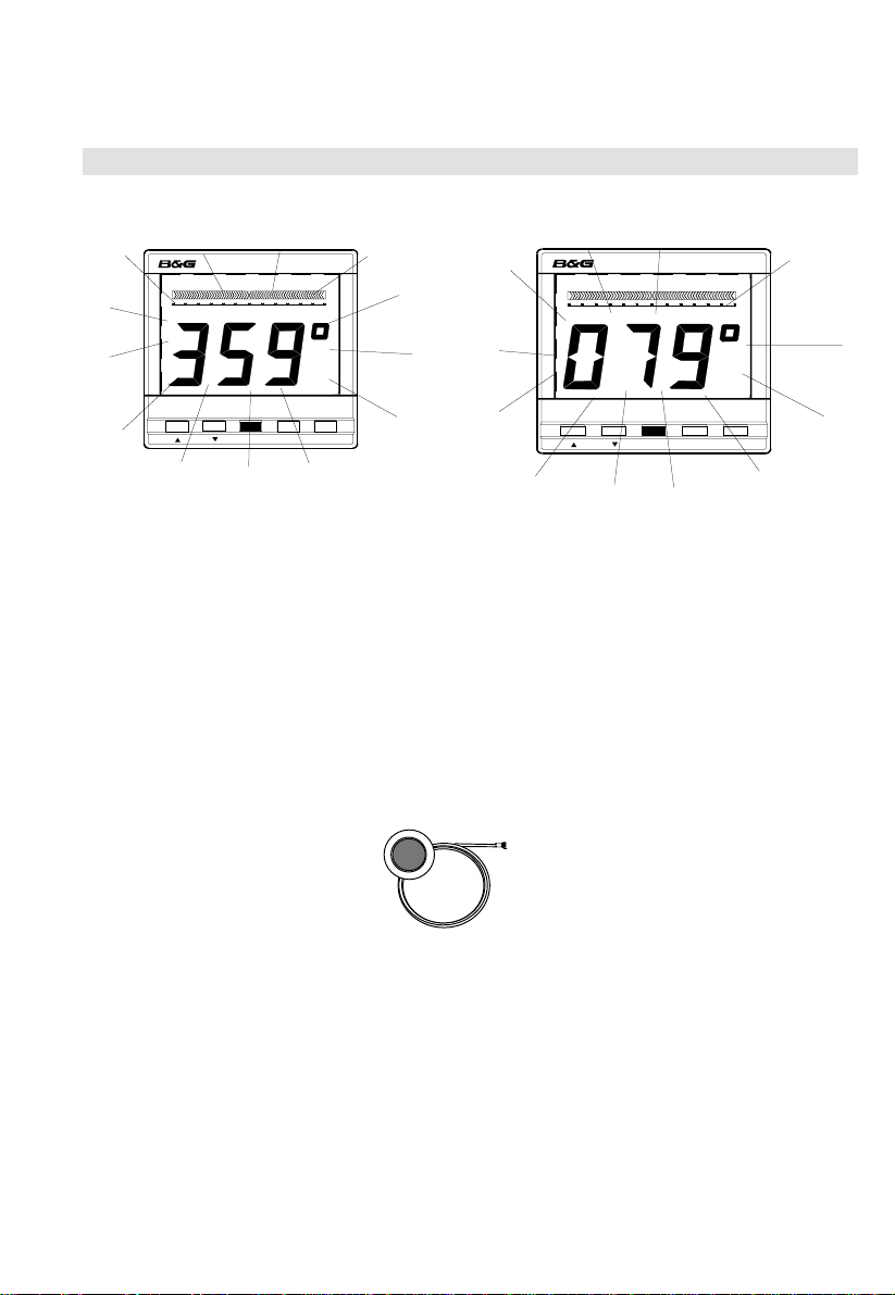
COMPASS DISPLAY UNIT......................................................................................4
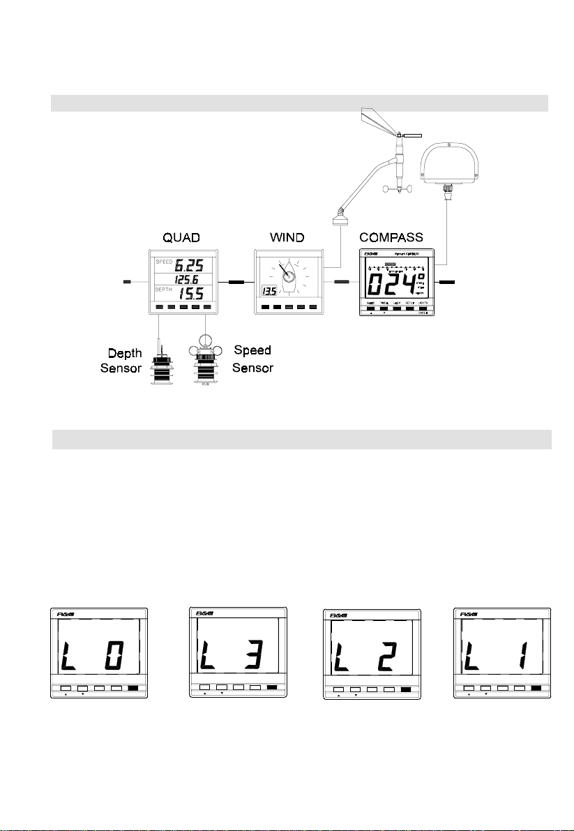
EXAMPLE SYSTEMS USING NETWORK COMPASS .......................................4
SETTING THE DISPLAY BACK LIGHTING........................................................5
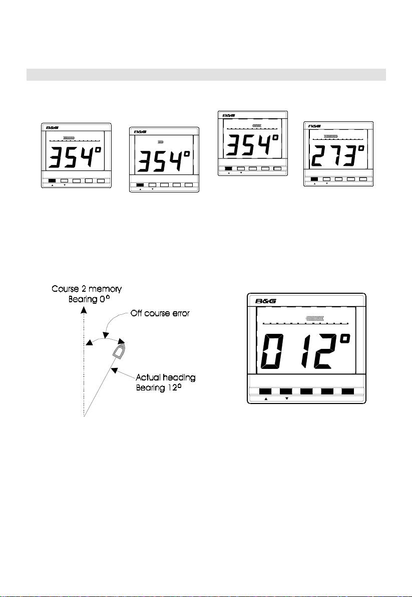
THE OFF COURSE DISPLAY..................................................................................6
SETTING THE COURSE MEMORIES...................................................................7
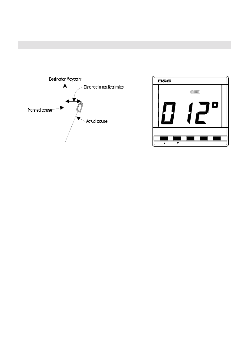
THE XTE DISPLAY...................................................................................................8
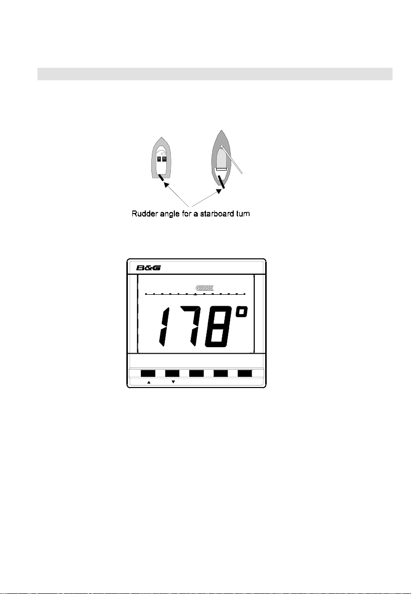
THE RUDDER DISPLAY..........................................................................................9
THE HEAD/LIFT DISPLAY ...................................................................................10
USING THE TIMER.................................................................................................11
SETTING THE TIMER............................................................................................12
ENABLING/DISABLING THE TIMER BEEPS...................................................12
ENABLING THE OFF COURSE ALARM............................................................13
SETTING THE COMPASS DAMPING.................................................................13
SETTING THE COMPASS OFFSET.....................................................................14
SETTING THE VARIATION..................................................................................14
SETTING THE DISPLAY FOR TRUE OR MAGNETIC READINGS..............15
ENABLING THE HEAD/LIFT MODE..................................................................15
SELECTING THE DISPLAY MODE.....................................................................16
CALIBRATING THE COMPASS...........................................................................16
OPERATION WITH AUTOPILOTS......................................................................17
TROUBLESHOOTING............................................................................................18
INSTALLATION.......................................................................................................19
SITING THE DISPLAY UNIT.....................................................................19
MOUNTING THE DISPLAY UNIT............................................................19
SITING THE FLUXGATE...........................................................................20
MOUNTING THE FLUXGATE ..................................................................20
INSTALLATION DATA ..........................................................................................21
SPECIFICATIONS...................................................................................................22
CONDITIONS OF WARRANTY............................................................................23
CONTENTS

2
Welcome to the B&G Network system. This world beating series of intelligent
navigational instruments has been brought to you through a combination of
scientific innovation and high quality production to create a computerised data
system you can trust. As an intelligent system each unit can be used by itself to
display specific data, alternatively any combination of units can be linked into a
Network with units processing their own data or acting as repeaters for data
from other units. This Network providing a comprehensive navigational system.
Screened cables combined with the latest technology provide protection from
interference between units and other systems.
The Network system is continuously expanding your options and currently
consists of the following units:
INSTRUMENTS
Network SPEED
Network DEPTH
Network QUAD
Network WIND
Network TACK
Network DATA
Network COMPASS
NAVIGATIONAL AIDS
Network NAV
Network GPS
LCD CHART
AUTOPILOTS
Network PILOT
GENERAL INTRODUCTION TO B&G NETWORK

3
The Network COMPASS unit uses the latest advances in electronics to display
Off Course, Cross Track Error (XTE)*, Rudder* and Head/Lift information on an
easy to read Liquid Crystal Display (LCD). Five keys on the unit select the
displayed data, calibration factors and alarms.
It can operate as a standalone unit compass display or as part of an Integrated
B&G Network Instrument System. The unit can also operate as a repeater of
course data received via the Network. These connections plug directly into the
rear of the display.
The Network COMPASS includes two adjustable alarms:
•Off course alarm
•Head alarm
An internal alarm buzzer will sound and the display will flash when the alarm
condition is met. Other Network instruments will also sound their alarms and
flash their displays.
Additionally a racing timer with alarm signals at set intervals is included in the
unit.
* These functions will only appear if the relevant sensors i.e. GPS or PILOT are
in the system
INTRODUCTION TO NETWORK COMPASS

4
Up to four COMPASS units can be connected to the system. Only one of these
should be linked to a fluxgate and set to transducer mode, the other three must
be set to repeater mode. Refer to SELECTING THE DISPLAY MODE for
details. The MODE key then cycles the display through Off Course, Cross
Track Error (XTE), Rudder and Head/Lift displays (if enabled).
COMPASS DISPLAY UNIT
MODE TIMER LOCK SETUP LIGHTS
ENTER
Network COMPASS
30 20 10 302010
OFFCOURSE
PORT
CRSE 1
STEER
EXAMPLE SYSTEMS USING NETWORK COMPASS

5
The Network COMPASS display has three brightness settings or off. Pressing
the LIGHTS key cycles through these in the following order.
•
••
•L 0 OFF
•
••
•L 3 High
•
••
•L 2 Medium
•
••
•L 1 Low
EXAMPLE SYSTEMS USING NETWORK COMPASS contd.
SETTING THE DISPLAY BACK LIGHTING
MODE TIMER LOCK SETUP LIGHTS
ENTER
Network COMPASS
MODE TIMER LOCK SETUP LIGHTS
ENTER
Network COMPASS
MODE TIMER LOCK SETUP LIGHTS
ENTER
Network COMPASS
MODE TIMER LOCK SETUP LIGHTS
ENTER
Network COMPASS

6
Pressing the MODE key will cycle the display between Off Course, Cross Track
Error (XTE) if GPS is fitted, Rudder angle if Network PILOT fitted and the
Head/Lift display (if enabled).
The Off Course
Display The XTE
Display The Rudder Display The Head/Lift Display
with Network GPS with Network PILOT if enabled
The unit will autodetect the presence of a GPS or PILOT on the Network and
will activate the displays accordingly. The Off Course display is used to show
the difference between the current heading and the heading stored in the
selected course memory (see SETTING THE COURSE MEMORIES).
In this instance the vessel is heading starboard of the setting in course 2
memory, the display shows the current bearing. The Off Course scale is visible
below the bar graph which points to port, the legends STEER and PORT
indicate the direction required to steer to correct the error.
The Off Course scale indicates how many degrees the vessel is from its
intended heading.
THE OFF COURSE DISPLAY
MODE TIMER LOCK SETUP LIGHTS
ENTER
Network COMPASS
30 20 10 302010RUDDER
MODE TIMER LOCK SETUP LIGHTS
ENTER
Network COMPASS
LIFT
30 20 10 302010
PORT
MODE TIMER LOCK SETUP LIGHTS
ENTER
Network COMPASS
30 20 10 302010
OFFCOURSE
STBD
CRSE 1
STEER
MODE TIMER LOCK SETUP LIGHTS
ENTER
Network COMPASS
101.00.1XTE10 1.0 0.1
STBD
CRSE 1
STEER
MODE TIMER LOCK SETUP LIGHTS
ENTER
Network COMPASS
30 20 10 302010
OFFCOURSE
PORT
CRSE 2
STEER

7
Whilst in Off Course mode the two course memories may be set. The currently
active course memory is shown by the legend CRSE1 or CRSE2.
Pressing the LOCK key brings up the current course memory (e.g. CRSE1)
which will flash on the display. Pressing LOCK again displays the second
course memory (CRSE2). Whilst the setting is displayed it can be adjusted by
using the ▲and ▼keys (normally the MODE and TIMER keys). The display
will revert to normal four seconds after the last key is pressed.
Alternatively the displayed course memory can be reset by sailing on a heading
then depressing the LOCK key for one second. The current course will then be
stored in the selected course memory.
If a remote button, shown below, is fitted as an option then this performs the
same functions as the LOCK key.
The Optional Remote Button with 15m cable
SETTING THE COURSE MEMORIES
MODE TIMER LOCK SETUP LIGHTS
ENTER
Network COMPASS
30 20 10 302010
OFFCOURSE
PORT
CRSE 1
STEER
MODE TIMER LOCK SETUP LIGHTS
ENTER
Network COMPASS
30 20 10 302010
OFFCOURSE
STBD
CRSE 2
STEER

8
REQUIRES A GPS ON THE NETWORK. The Cross Track Error display is
used to indicate how far the vessel is from the intended track (from waypoint to
waypoint).
In this instance the vessel is heading starboard of the planned course. The
display shows the current bearing and the XTE scale is visible above the bar
graph which points to port, the legends STEER and PORT indicate the direction
required to steer to correct the error.
The XTE scale indicates how many nautical miles the vessel is from the track
(waypoint to waypoint).
THE XTE DISPLAY
MODE TIMER LOCK SETUP LIGHTS
ENTER
Network COMPASS
101.00.1XTE10 1.0 0.1
PORT
STEER

9
REQUIRES B&G NETWORK PILOT IN CIRCUIT. The rudder display indicates
the current angle of the rudder, which is particularly useful on wheel steered
boats.
The vessel is turning to starboard, the display shows the current heading and
the rudder scale is visible beneath the bar graph which points to port; the
direction to turn the wheel to straighten the rudder.
The scale indicates the degrees at which the rudder is angled.
THE RUDDER DISPLAY
MODE TIMER LOCK SETUP LIGHTS
ENTER
Network COMPASS
30 20 10 302010RUDDER

10
THE HEAD/LIFT PAGE HAS TO BE ENABLED IN THE SET UP MENU before
it can be displayed.
The port and starboard tacks are stored manually as PORT and STBD
headings (see SETTING THE COURSE MEMORIES). When the helmsman
has to vary from these headings due to wind changes the legends HEAD or
LIFT will appear on the display for the relevant tack. If wind data is available
over the Network a tack will automatically change between the PORT and
STBD reference course. Otherwise it can be switched manually by two short
presses of the LOCK key or the remote button. The HEAD/LIFT values are
displayed in the analogue bar graph as degrees. If the Off Course alarm is
enabled the unit will sound an alarm and HEAD will flash if a head occurs,
pressing ENTER on the unit will cancel the alarm. The alarm will not sound for
a lift.
THE HEAD/LIFT DISPLAY
MODE TIMER LOCK SETUP LIGHTS
ENTER
Network COMPASS
LIFT
30 20 10 302010
PORT
MODE TIMER LOCK SETUP LIGHTS
ENTER
Network COMPASS
LIFT
30 20 10 302010
STBD
MODE TIMER LOCK SETUP LIGHTS
ENTER
Network COMPASS
HEAD
30 20 10 302010
STBD
MODE TIMER LOCK SETUP LIGHTS
ENTER
Network COMPASS
HEAD
30 20 10 302010
PORT

11
Pressing the TIMER key enters the timer display mode, this is shown by the
presence of a colon which flashes every second.
The timer can be set to any required value to a maximum time period of 99
hours 59 minutes and 50 seconds. The analogue bar graph shows the time left,
in minutes, from 30 minutes before time zero (bar graph on the left) to 30
minutes after (bar graph on the right).
The unit will also beep to indicate the passage of set units of time, the number
and frequency of beeps depending on the time left to time zero, there are no
beeps after time zero. The beep sequences are shown in the table below.
Beeps begin at Beeps end at Number of beeps Frequency
< 60 hours 1 hour 5 every hour
< 1 hour =>10 minutes 4 every 10 minutes
< 10 minutes => 1 minute 3 every minute
< 1 minute => 10 seconds 2 every 10 seconds
< 10 seconds >0 1 every second
= 0 >-10 seconds continuous for 10 seconds
This means that for the example given above of 1 hour 48 minutes the following
beeps will occur:
•5 beeps at 1:00
•4 beeps at 0:50; 0:40; 0:30; 0:20; 0:10
•3 beeps at 0:09; 0:08; 0:07; 0:06...0:01
•2 beeps at 0:00:50; 0:00:40...0:00:10
•1 beep at 0:00:09; 0:00:08; 0:00:07...0:00:01
•continuous beep at 0:00:00 for ten seconds
At each of these periods the display will briefly show the time left.
Press MODE to return to the heading display.
USING THE TIMER
MODE TIMER LOCK SETUP LIGHTS
ENTER
Network COMPASS
30 20 10 302010

12
1. Press TIMER to enter timer mode.
2. Press SETUP to give the display h:xx (xx represents a two digit number) the
hwill be flashing.
3. Press ENTER and the numbers will flash.
4. Alter the hours using the ▲ or ▼keys. If the key is held down the numbers
will change more quickly.
5. Press ENTER to adjust the count down minutes. The display will show the
current minutes setting and the bar graph on the left will represent the
minutes before time zero (up to 30 minutes).
6. Alter the minutes using the ▲or ▼keys.
7. Press ENTER to set the timer, with the seconds set to zero. Both sides of
the bar graph will now be full to show that the timer is ready to be started.
8. Press ENTER to start the timer and exit to the timer display.
1. Press TIMER to enter timer mode.
2. Press SETUP to give the display h:xx (xx represents a two digit number) the
hwill be flashing.
3. Press SETUP to give the O:FF display (colon flashing).
4. Press enter, the OFF will flash.
5. Press ▲ or ▼ keys to change this to ON, enabling the beeps.
6. Press ENTER to store the new setting.
7. Press SETUP to return the unit to the timer set-up display.
8. Press MODE/TIMER to return to desired mode.
SETTING THE TIMER
MODE TIMER LOCK SETUP LIGHTS
ENTER
Network COMPASS
MODE TIMER LOCK SETUP LIGHTS
ENTER
Network COMPASS
MODE TIMER LOCK SETUP LIGHTS
ENTER
Network COMPASS
MODE TIMER LOCK SETUP LIGHTS
ENTER
Network COMPASS
MODE TIMER LOCK SETUP LIGHTS
ENTER
Network COMPASS
30 20 10 302010
ENABLING/DISABLING THE TIMER BEEPS
MODE TIMER LOCK SETUP LIGHTS
ENTER
Network COMPASS
MODE TIMER LOCK SETUP LIGHTS
ENTER
Network COMPASS
MODE TIMER LOCK SETUP LIGHTS
ENTER
Network COMPASS

13
1. Press SETUP until the OFFCOURSE legend flashes to indicate the alarm
set up display. This value is preset to 0°which is shown as OFF.
2. Press ENTER then OFF will flash.
3. Press the ▲ or ▲keys to the desired value (between 0°and 30°).
4. Press ENTER to accept value and return to set-up mode.
5. Press MODE to return to desired mode.
Compass damping is used to smooth out compass readings.
1. Press SETUP until dxx is displayed. The dwill flash.
2. Press ENTER, the numbers will flash.
3. Press the ▲ or ▼ keys until the desired value is shown (between 1 and 99
seconds).
4. Press ENTER to accept value and return to set-up mode.
5. Press MODE to return to desired mode.
ENABLING THE OFF COURSE ALARM
MODE TIMER LOCK SETUP LIGHTS
ENTER
Network COMPASS
OFFCOURSE
SETTING THE COMPASS DAMPING
MODE TIMER LOCK SETUP LIGHTS
ENTER
Network COMPASS
SETTING THE COMPASS OFFSET

14
The compass offset compensates for fixed errors in the compass after
installation and calibration such as sensor orientation.
1. Press SETUP until a bearing is displayed and the degrees sign is flashing.
2. Press ENTER, the numbers will flash.
3. Press the ▲ or ▼ keys until the desired value is shown (between +180 and
-180 seconds). A positive offset has a bar graph on the right of the display,
a negative offset has a bar graph on the left of the display
4. Press ENTER to accept value and return to set-up mode.
5. Press MODE to return to desired mode.
Compass Offset at -3°Compass Offset at +7°
1. Press SETUP until Uxx is displayed (xx represents a number) and the U is
flashing.
2. Press ENTER, the numbers will flash.
3. Press the ▲ or ▼ keys until the desired value is shown (between 90W and
90E). An easterly variation has a bar graph on the right of the display, a
westerly variation has a bar graph on the left of the display.
4. Press ENTER to accept value and return to set-up mode.
5. Press MODE to return to desired mode.
Variation is 5°E Variation is 7°W
MODE TIMER LOCK SETUP LIGHTS
ENTER
Network COMPASS
MODE TIMER LOCK SETUP LIGHTS
ENTER
Network COMPASS
SETTING THE VARIATION
MODE TIMER LOCK SETUP LIGHTS
ENTER
Network COMPASS
MODE TIMER LOCK SETUP LIGHTS
ENTER
Network COMPASS

15
1. Press SETUP until TRUE is flashing and either ON or OFF is displayed.
2. Press ENTER, ON or OFF will flash.
3. Press the ▲ or ▼ keys to switch the setting between on and off
4. Press ENTER to accept the setting and return to set-up mode.
5. Press MODE to return to desired mode.
Compass will display TRUE headings Compass will display MAGNETIC headings
1. Press SETUP until HEAD/LIFT is flashing and either ON or OFF is
displayed.
2. Press ENTER, ON or OFF will flash.
3. Press the ▲ or ▼ keys to switch the setting between on and off
4. Press ENTER to accept the setting and return to set-up mode.
5. Press MODE to return to desired mode.
SETTING THE DISPLAY FOR TRUE OR MAGNETIC READINGS
MODE TIMER LOCK SETUP LIGHTS
ENTER
Network COMPASS
TRUE
MODE TIMER LOCK SETUP LIGHTS
ENTER
Network COMPASS
TRUE
ENABLING THE HEAD/LIFT MODE
MODE TIMER LOCK SETUP LIGHTS
ENTER
Network COMPASS
LIFTHEAD
MODE TIMER LOCK SETUP LIGHTS
ENTER
Network COMPASS
LIFTHEAD

16
1. Press SETUP until a flashing tand either ror tis displayed.
2. Press ENTER, ror twill flash.
3. Press the ▲ or ▼ keys to switch the setting between repeater (r) and
transducer (t).
4. Press ENTER to accept the setting and return to set-up mode.
5. Press MODE to return to desired mode.
Unit set to repeater mode Unit set to transducer mode
Remember that a compass offset may be entered (see section SETTING THE
COMPASS OFFSET).
1. Press SETUP until the rotating segment is displayed.
2. Press ENTER to begin calibration swing. The display shows a degree count.
3. Sail the vessel through a full circle, the display will count up to 360.
4. On completion the compass will display a -P- for pass or a -F- for fail (see
troubleshooting).
5. Press ENTER to accept the calibration, the rotating segment will reappear.
6. Press MODE to return to desired mode.
When the display shows a clockwise rotating segment press ENTER and turn the boat through a full circle
SELECTING THE DISPLAY MODE
MODE TIMER LOCK SETUP LIGHTS
ENTER
Network COMPASS
MODE TIMER LOCK SETUP LIGHTS
ENTER
Network COMPASS
CALIBRATING THE COMPASS
MODE TIMER LOCK SETUP LIGHTS
ENTER
Network COMPASS

17
REQUIRES A B&G NETWORK AUTOPILOT IN SYSTEM. If a B&G Network
autopilot is present in the system, and the unit is set up within a system that
includes a Network ACP1 or ACP2 then there are two options for the Network
configuration.
•The COMPASS unit can display rudder and compass information
generated by the PILOT.
•The fluxgate sensor can be connected to the COMPASS unit giving an
alternate remote fluxgate option.
The Network is more efficient if the fluxgate is connected to the Network ACP
Pilot and the COMPASS is used as a repeater for the data but the system will
operate normally with the pilot accepting data from the COMPASS unit.
Only one fluxgate is necessary for the Network but if a backup fluxgate is added
and fitted into the COMPASS unit then it will override the PILOT's internal
compass. The PILOT will then act as a repeater for the COMPASS data. It is
important that the COMPASS is specifically set up in repeater mode. The
fluxgate on the Network COMPASS may be enabled by changing modes in the
event of a PILOT/FLUXGATE failure.
PILOT Off Course data is not fed into the COMPASS unit through the Network.
If this information is required the PILOT heading can be manually entered into
one of the COMPASS course memories.
OPERATION WITH AUTOPILOTS
PILOT
MODE TIMER LOCK SETUP LIGHTS
ENTER
Network COMPASS
30 20 10 302010
OFFCOURSE
STBD
CRSE 1
STEER
COMPASS
TROUBLESHOOTING

18
PROBLEM POSSIBLE CAUSE
Display fails to light up Power not connected.
Supply not 10 to 16 Volts.
Data is not repeated from Network Compass not in repeater mode.
Cables not correctly fitted.
Compass fails to calibrate (-F-) Calibration manoeuvre performed badly.
Compass installed too close to onboard
metallic object.
Calibration manoeuvre attempted near to
large metallic vessel or equipment, e.g.
loading crane.
Display shows Efollowed by Error message. Switch off and restart. (If
a number the message persists after three restart
attempts contact your authorised dealer
for assistance.)
-C- error message Compass fluxgate error. Switch off check
wiring. (If the message persists after three
restart attempts contact your authorised
dealer for assistance.)

19
The display heads are supplied with a clip-in mounting bracket which allows for
easy installation, access from behind is not necessary to secure the unit in
place. However to prevent theft and permanently fix the unit in position, locking
studs and thumb nuts are supplied.
All Network Instruments are designed for mounting on or below deck. A
mounting position should be selected where they are:
•Easy to read by the helmsman
•On a smooth and flat surface
•At least 100mm (4") from a compass
•Accessible from behind for fitting locking studs if required.
Use the cutting template supplied to mark the centres of the holes for the self-
tapping screw, the fixing stud holes and the mounting bracket.
•The template allows 4mm (5/32") between adjacent units for the suncover,
increase this distance if required to maximum of 60mm (2 3/8") between
units or 180mm (3 1/8") between centres. For greater distances between
units extension cables are available.
•
••
•Use a 70mm (2 3/4") diameter hole-cutter for the mounting bracket hole.
•
••
•Use a 2.9mm for the self-tapping screw holes. Use a 5mm (3/32") drill for
the locking stud holes.
•
••
•Secure the mounting bracket to the bulkhead with the self-tapping screws
supplied
•
••
•Fit the rubber sealing gasket around the mounting bracket.
•
••
•Screw the locking studs into the back of the display head (if required).
•
••
•Carefully pass the cable tails through the mounting bracket hole, connect
the cables to the main units.
•
••
•Clip the display head into the mounting bracket.
•
••
•Secure the instrument with the thumb nuts supplied.
INSTALLATION
SITING THE DISPLAY UNIT
MOUNTING THE DISPLAY UNIT
Other manuals for Network Series
2
This manual suits for next models
1
Table of contents
Other B&G Marine Equipment manuals

B&G
B&G RAM T0 User manual

B&G
B&G H5000 Pilot User manual

B&G
B&G HB-1000I User manual

B&G
B&G Triton Edge User manual

B&G
B&G H1000-WDI User manual

B&G
B&G h1000 pilot User manual

B&G
B&G H5000 Pilot Use and care manual

B&G
B&G Triton Display User manual

B&G
B&G h1000 pilot User manual

B&G
B&G Hydra 2000 User manual