Installation and Technical Information
BEGA
Due to the dynamic nature of lighting products and the associated technologies, luminaire data on this sheet is subject to change at the discretion of BEGA North America. For the most current technical data, please refer to bega-us.com
BEGA 1000 Bega Way, Carpinteria, CA 93013 (805)684-0533 © copyright BEGA 2022
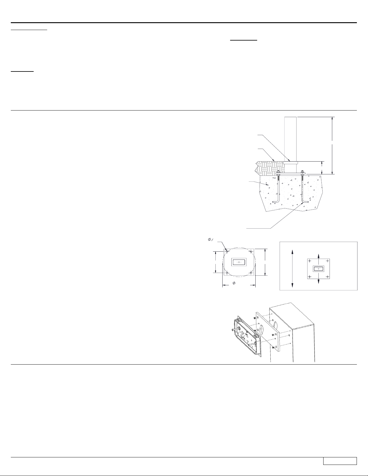
Figure 1:
Overview:
LED Watts: 17.6W
System Watts: 22.0W
Controllability: 0-10V dimmable
Weight: 124.3 lbs.
Protection Class: IP65
Tools Required:
• 5mm hex head screwdriver
• 4mm hex head screwdriver
• 3mm hex head screwdriver
• T25 torx head screwdriver
• Special tool (provided by BEGA)
• Adjustable wrench
Figure 2: Figure 3:
Figure 4:
13 3/8"
BOLT CIRCLE
11 3/4"
9 1/2"
3
4
"
4 PLC.
25 3/8"
5 3/4"
-
79802
ANCHOR KIT - INCLUDED
2/28/2022
IMPORTANT! ANCHOR ORIENTATION
LIGHT OUTPUT
LIGHT OUTPUT
DIRECTION OF LIGHT
TOP VIEW
IMPORTANT!
CORNERS OF BASE &
LUMINAIRE MUST BE
ALIGNED IN DESIRED
LOCATION &
ORIENTATION. SEE DETAIL.
FINISHED GRADE
(4) 5/8" X 14" X 2" 'L'
ANCHOR BOLTS WITH
LEVELING WASHERS,
LOCK WASHERS, AND
HEX NUTS
THIS SURFACE MUST
BE FLUSH TO
FINISHED GRADE
CONCRETE
FOOTING
13 3/8"
BOLT CIRCLE
11 3/4"
9 1/2"
3
4
"
4 PLC.
25 3/8"
5 3/4"
NOT TO SCALE
SHEET 2 OF 3
B
1000 BEGA Way, Carpinteria, California 93013
DESCRIPTION:
P (805) 684-0533 - www.bega-us.com
APPROVED:
DATE:
THE INFORMATION CONTAINED IN THIS DRAWING IS THE SOLE PROPERTY
OF BEGA NORTH AMERICA, INC.
ANY REPRODUCTION IN PART OR AS A WHOLE WITHOUT THE WRITTEN
PERMISSION OF BEGA NORTH AMERICA, INC. IS PROHIBITED.
PROPRIETARY AND CONFIDENTIAL
TYPE:
SIZE
PART NO.
REV
REV
CHANGED BY
DESCRIPTION
DATE
Building element - asymmetric · single 84 240
Dimensions
A: 9-1/2
B: 12-3/8
C: 177-1/8
Maintenance:
Clean regularly with solvent-free cleaner
removing dirt and debris. Do not use high
pressure cleaners.
Replacement Parts
See label inside of xture for LED replacement
part number.
Consult factory for all other replacement
components.
Accessories
Please refer to the appropriate accessory installation
sheet for further instruction when applicable.
Updated: 03/03/22
84 240 1 of 3
Notice to Installer:
1. See page 3 for specic product safety warnings.
2. Fixture may be damaged if connected to conduit systems that contain water - Article
300-5G of the National Electric Code requires that “Conduits or raceways through
which moisture may contact energized live parts shall be sealed or plugged at either
or both ends.”
3. Fixture ships in two parts, the head and post will be in separate boxes.
79802 Anchor installation:
1. Anchor kit 79802 must be installed in concrete. This anchorage kit is buried below
the nished grade. Attention to alignment, leveling, and location is required for
proper installation See Figure 1.
2. Provide means to bring supply wiring to luminaire in accordance with local code. The
template has a 2-1/8”x 4-1/2” conduit opening for conduit entry. Provide adequate
foundation reinforcement for the intended load (by others).
3. Use template (Figure 2) and anchor bolts provided. Anchor bolts can be installed by
either attaching template to concrete form, or by inserting anchor bolts into poured
concrete. Ensure template and anchor bolts are leveled properly.
4. IMPORTANT: Align and level template so the orientation of the rectangular
conduit hole matches the desired orientation of the linear element (Figure 3).
Make sure anchor bolts will not protrude from concrete foundation more than 2-1/4”.
5. Once the concrete footing is set, remove template and pull supply wiring through
anchor base to a height of 36” to allow for wiring connections to be made later.
6. Attach anchor base to anchor bolts using leveling washers, lock washers, and hex
nuts (provided).
7. Install nished grade.
84240 luminaire installation:
1. Fixture ships in two parts. Assemble top of luminaire and post together. Do not install
post without head attached.
2. Remove top of post by inserting a at head screwdriver into one of the grooves on
the side of the post. Lift to remove.
3. Open xture head by loosening (2) 3mm hex head screws near xture lens.
Disassemble xture head and mounting plate as shown in Figure 4.
4. Secure mounting plates to post by tightening (4) T25 torx head screws and (2) 4mm
hex head screws as shown in Figure 4.
5. Route wires from luminaire head through mounting plate and post to access door for
connections to be made later.
6. Replace the rest of the xture head ensuring gasket is seated correctly. Tighten (2)
3mm hex head screws to secure. Replace post cap.
7. Place post over anchor base ensuring the xture is oriented correctly for desired light
output direction.
8. Secure post to anchor base by tightening (8) 5mm hex head screws at the base of
the post.
9. Open access door by using the special tool provided by BEGA.
10. Make supply wiring connections in the base of the post
MAIN VOLTAGE SUPPLY WIRE TO BLACK LUMINAIRE WIRE
NEUTRAL (COMMON) SUPPLY WIRE TO WHITE LUMINAIRE WIRE
GREEN GROUND WIRE TO GREEN LUMINAIRE WIRE
0-10V dimming (if applicable):
DIM CONTROL WIRE (+) TO POSITIVE LUMINAIRE DIM CONTROL WIRE
DIM CONTROL WIRE (-) TO NEGATIVE LUMINAIRE DIM CONTROL WIRE
11. Close access door.
13 3/8"
BOLT CIRCLE
11 3/4"
9 1/2"
3
4
"
4 PLC.
25 3/8"
5 3/4"
-
79802
ANCHOR KIT - INCLUDED
2/28/2022
IMPORTANT! ANCHOR ORIENTATION
LIGHT OUTPUT
LIGHT OUTPUT
DIRECTION OF LIGHT
TOP VIEW
IMPORTANT!
CORNERS OF BASE &
LUMINAIRE MUST BE
ALIGNED IN DESIRED
LOCATION &
ORIENTATION. SEE DETAIL.
FINISHED GRADE
(4) 5/8" X 14" X 2" 'L'
ANCHOR BOLTS WITH
LEVELING WASHERS,
LOCK WASHERS, AND
HEX NUTS
THIS SURFACE MUST
BE FLUSH TO
FINISHED GRADE
CONCRETE
FOOTING
13 3/8"
BOLT CIRCLE
11 3/4"
9 1/2"
3
4
"
4 PLC.
25 3/8"
5 3/4"
NOT TO SCALE
SHEET 2 OF 3
B
1000 BEGA Way, Carpinteria, California 93013
DESCRIPTION:
P (805) 684-0533 - www.bega-us.com
APPROVED:
DATE:
THE INFORMATION CONTAINED IN THIS DRAWING IS THE SOLE PROPERTY
OF BEGA NORTH AMERICA, INC.
ANY REPRODUCTION IN PART OR AS A WHOLE WITHOUT THE WRITTEN
PERMISSION OF BEGA NORTH AMERICA, INC. IS PROHIBITED.
PROPRIETARY AND CONFIDENTIAL
TYPE:
SIZE
PART NO.
REV
REV
CHANGED BY
DESCRIPTION
DATE
13 3/8"
BOLT CIRCLE
11 3/4"
9 1/2"
3
4
"
4 PLC.
25 3/8"
5 3/4"
-
79802
ANCHOR KIT - INCLUDED
2/28/2022
IMPORTANT! ANCHOR ORIENTATION
LIGHT OUTPUT
LIGHT OUTPUT
DIRECTION OF LIGHT
TOP VIEW
IMPORTANT!
CORNERS OF BASE &
LUMINAIRE MUST BE
ALIGNED IN DESIRED
LOCATION &
ORIENTATION. SEE DETAIL.
FINISHED GRADE
(4) 5/8" X 14" X 2" 'L'
ANCHOR BOLTS WITH
LEVELING WASHERS,
LOCK WASHERS, AND
HEX NUTS
THIS SURFACE MUST
BE FLUSH TO
FINISHED GRADE
CONCRETE
FOOTING
13 3/8"
BOLT CIRCLE
11 3/4"
9 1/2"
3
4
"
4 PLC.
25 3/8"
5 3/4"
NOT TO SCALE
SHEET 2 OF 3
B
1000 BEGA Way, Carpinteria, California 93013
DESCRIPTION:
P (805) 684-0533 - www.bega-us.com
APPROVED:
DATE:
THE INFORMATION CONTAINED IN THIS DRAWING IS THE SOLE PROPERTY
OF BEGA NORTH AMERICA, INC.
ANY REPRODUCTION IN PART OR AS A WHOLE WITHOUT THE WRITTEN
PERMISSION OF BEGA NORTH AMERICA, INC. IS PROHIBITED.
PROPRIETARY AND CONFIDENTIAL
TYPE:
SIZE
PART NO.
REV
REV
CHANGED BY
DESCRIPTION
DATE


