7
5. INSTALLATION
5.1 Location
The BA304NC indicator can be supplied in either a
glass reinforced polyester (GRP), or an epoxy
painted aluminium enclosure. Both provide IP66
protection and have a polycarbonate window and
stainless steel fittings. The GRP enclosure is
suitable for most industrial installations including
off-shore and waste water treatment applications.
For installations where solvents may be present,
the aluminium enclosure provides maximum
protection, but it is not recommended for offshore
applications.
Both enclosures are surface mounting, but may be
pipe or panel mounted using the accessory kits
described in section 8 of this manual.
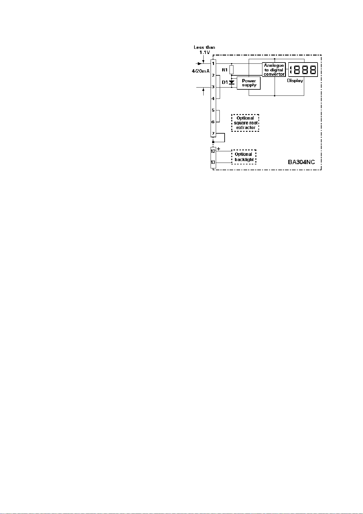
To simplify installation, the enclosure can be
installed and the field wiring terminated prior to the
indicator assembly being fitted. The enclosure
contains diodes to maintain continuity of the
4/20mA loop when the indicator assembly is not
present. Terminals 2 and 4 are internally joined
and may be used for linking the return 4/20mA wire
- see Fig 2. Similarly, terminals 5 and 6 are
internally joined and may be used for linking the
cable screens. Terminal 7 is internally connected
to an insulated radio frequency screen in the GRP
enclosure, and to the case in the aluminium
enclosure.
5.2 Installation Procedure
Fig 4 illustrates the instrument installation
procedure.
a. Remove the enclosure cover by unscrewing
the four captive 'A' screws.
b. Remove the indicator assembly from the
enclosure by unscrewing the three captive 'B'
screws.
c. Mount the enclosure on a flat surface and
secure with screws or bolts through the four
corner 'C' holes. Alternatively use one of the
pipe or panel mounting kits described in
sections 8.4 and 8.5
d. Remove the temporary hole plug and install
an Ex e or Ex n cable gland or conduit fitting.
If two entries are required, the stopping plug
may be replaced with an Ex e or Ex n cable
gland or conduit fitting.
e. Connect the field wiring to the terminals as
shown in Fig 5.
f. Replace the indicator assembly and evenly
tighten the three 'B' screws.
g. Replace the enclosure cover and evenly
tighten the four 'A' screws.
Fig 4 BA304NC installation procedure
Comprehensive installation information for
Ex nA [extra low voltage] instrumentation is
contained in the BEKA Application Guide AG310
which may be downloaded from the BEKA website
www.beka.co.uk.